week 13. Networking and communications
Group Assignment
This week we are divided into two groups as boys and girls so boys will be working on wireless nodes while girls will be working on wired.
Group Member ;
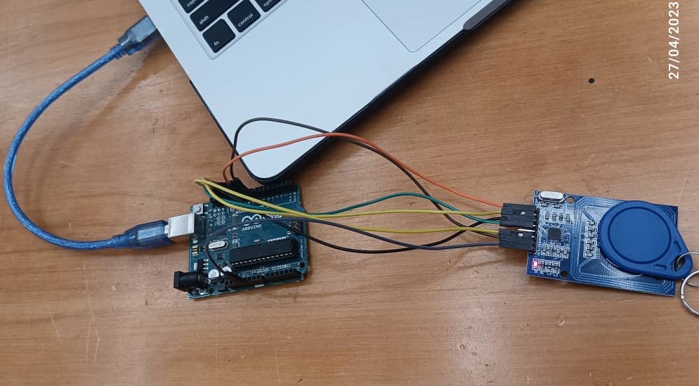
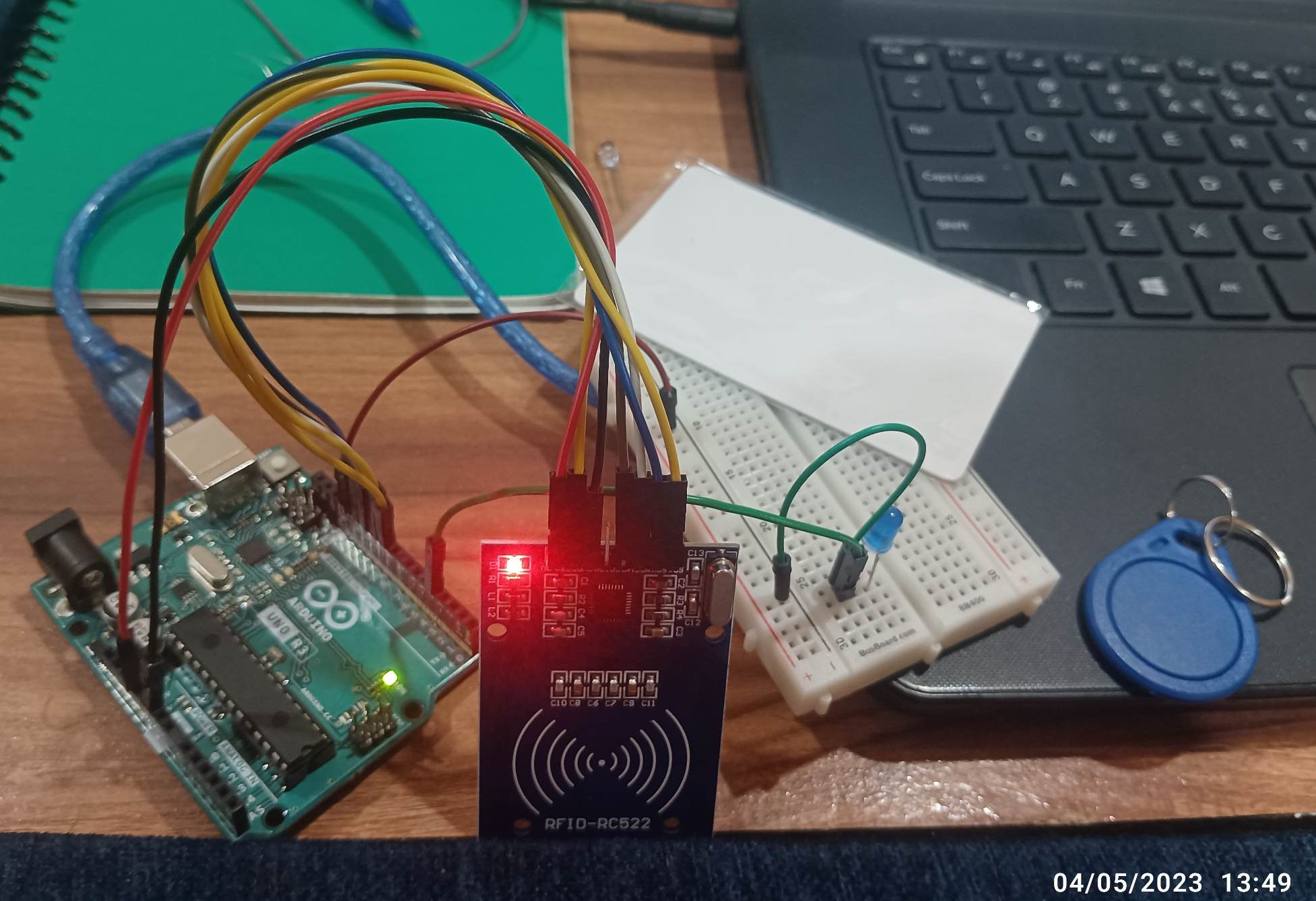
1. Our group will be working on RFID Reader so firstly we solder the RFID pin out with an 8 pin header.
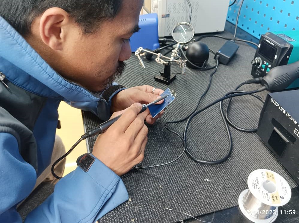
2. After done with soldering we started to go through RFID Reader pin out and done the connection with Arudino
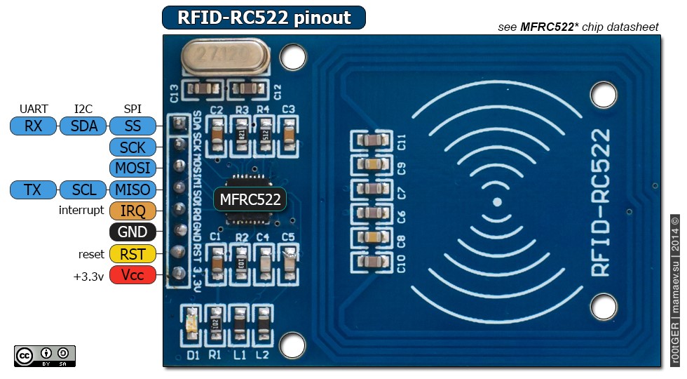
RFID Module Pinout
VCC supplies power to the module.
RST is an input for reset and power-down.
GND is the ground pin and needs to be connected to the GND pin on the Arduino.
IRQ is an interrupt pin that alerts the microcontroller when an RFID tag is in the vicinity.
MISO pin acts as master-in-slave-out when SPI interface is enabled.
MOSI is the SPI input to the RC522 module.
SCK accepts the clock pulses provided by the SPI bus master
SDA pin acts as a signal input when the SPI interface is enabled.
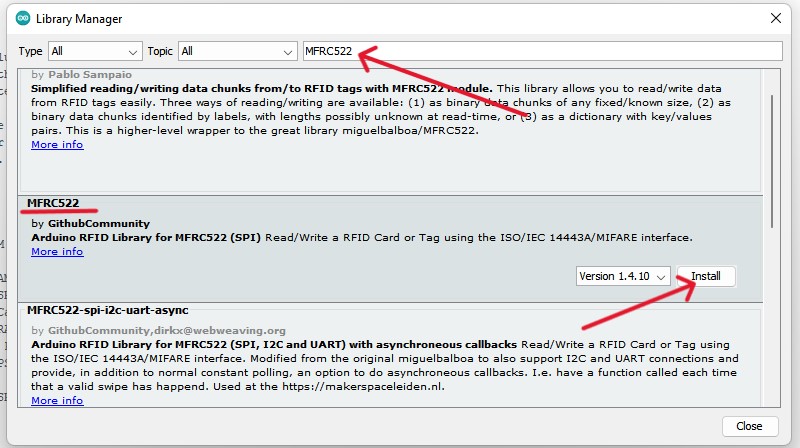
3. Now we connect it to the computer and open the Arduino. And we have to install the MFRC522 library by going to tools >> manage library.
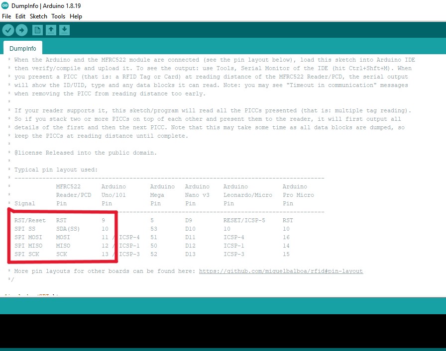
4. Go to file >> Examples >> MFRC522 >> click on Dumpinfo to get the path:
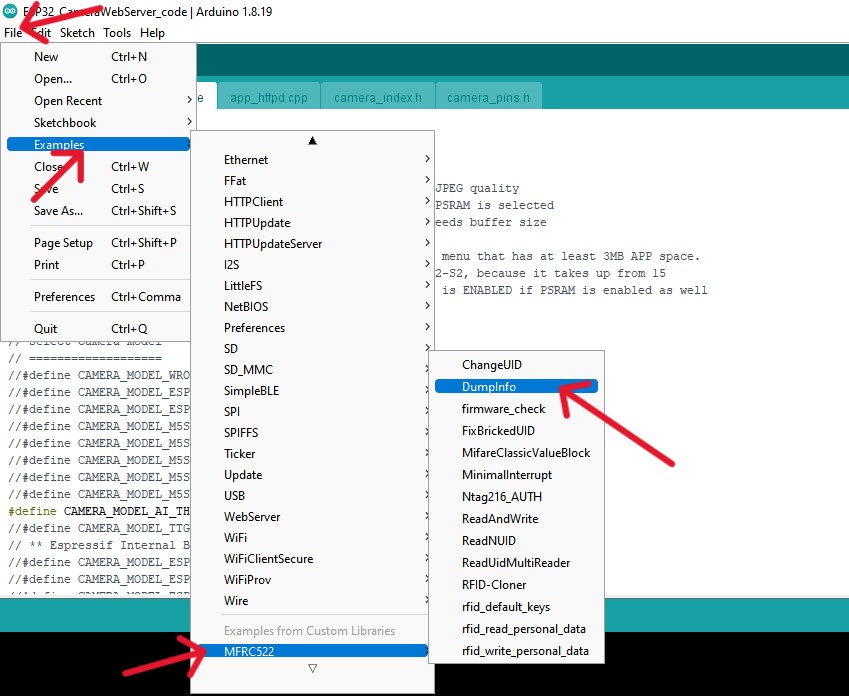
5. After you click on the dumpinfo, your coding will be displayed. The code tells you where to connect the pins on the RFID reader. So crosscheck your connections that you have done and upload code to the board.
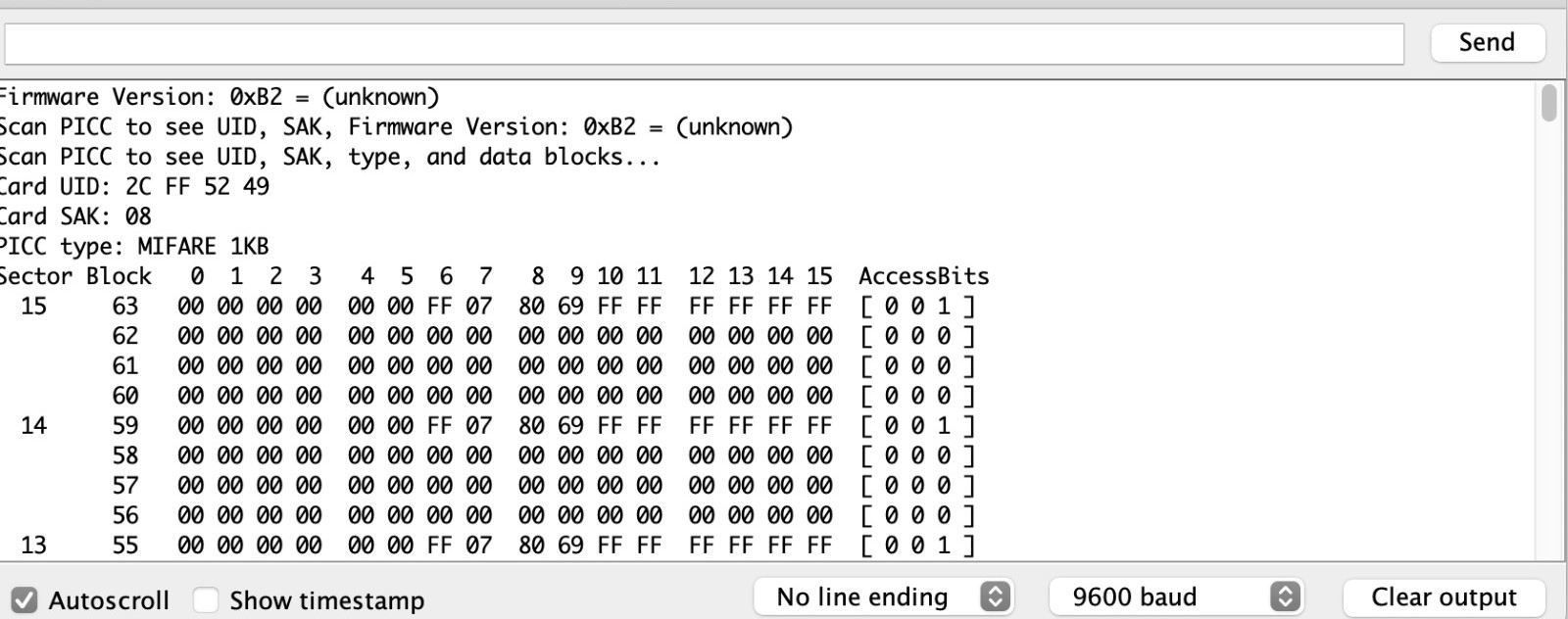
6. Once the code is uploaded, bring the tag close to the RFID reader. The reader picks up the signal and spits out information about the tag.
Hero shot
Final Video
Add LED Light
Connect the LED light and resistor to the breadboard as shown in the circuit diagram as we did.
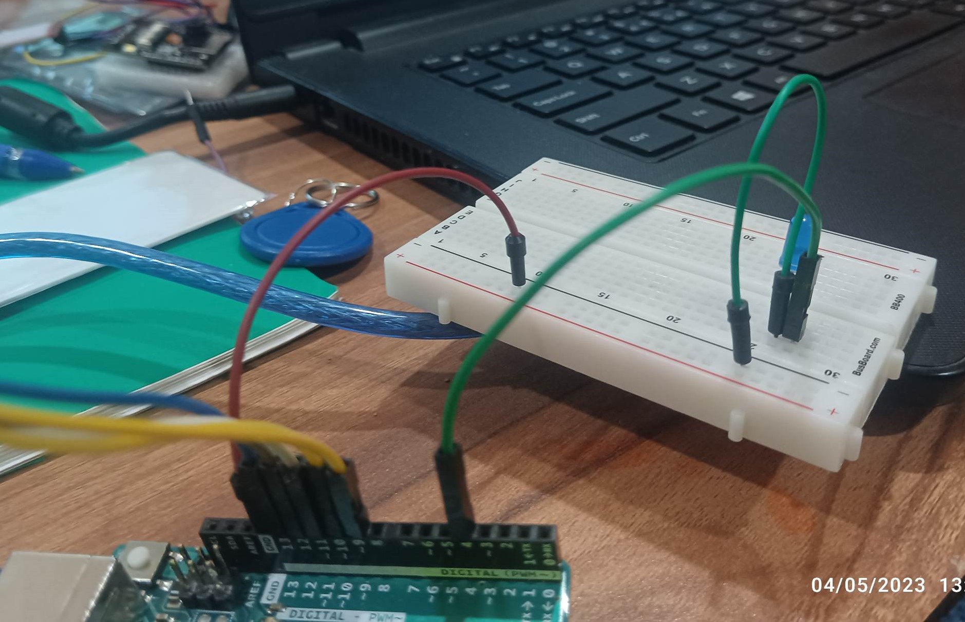
Circuit diagram for connecting LED (left) and Image of completed circuit with RFID sensor and LED light (right)
Upload and Run Code
Open it in the Arduino IDE. This sketch is similar to the DumpInfo example sketch, but also turns on and off an LED light when the RFID Card is detected. Move an RFID Tag or Card at reading distance of the RFID sensor. You should see the LED light blink once.
LED with RFID Video
Design File
aIndividual Assignment
For this week i want to use ESP32 CAM for networking and communications as i used this for my final project. The ESP 32 cam module has very limited GPIO pins hence most of the pins of the microcontroller are used for the camera.
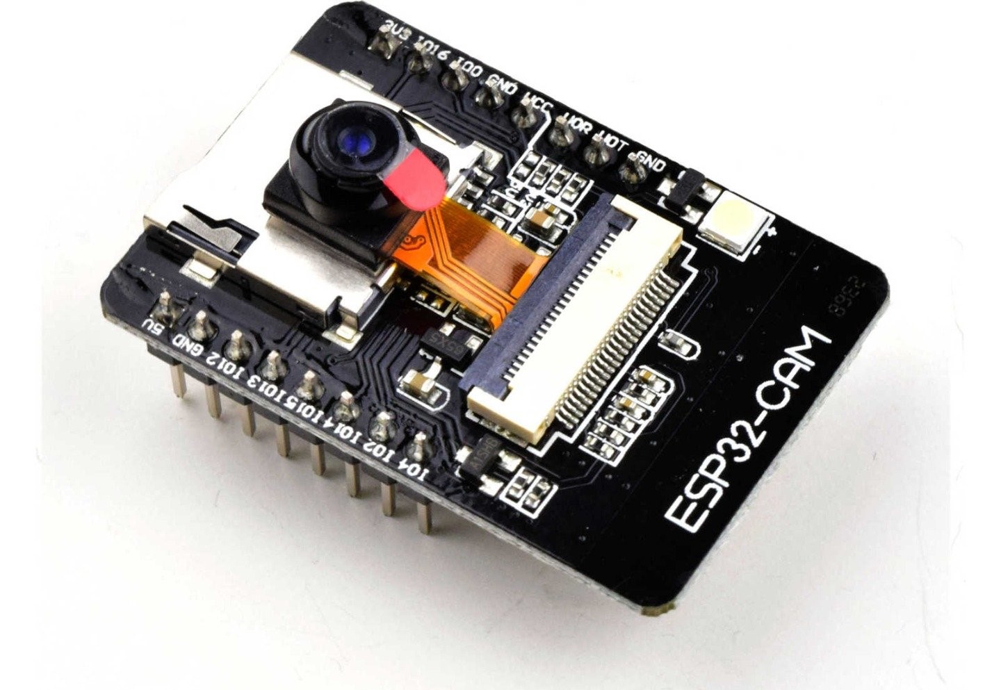
I used this great tutorial to get started working with the ESP 32 cam. The first thing to know regarding the cam module, is that it doesn’t come with USB connector, thus I needed use the FTDI cable to program it using the serial pins (TX, RX).
Milling Board
For milling my ESP32 Cam mounting PCB board i have used FabAcademy Website as a reference and I downloaded the boards’ interior and traces from Mr.Maha Al Hashimi page. So then i Used MODS to create the rml files and then milled it using the ROLAND SRM20.
1. 2x 1x8 2.54mm connectors
2. 1x Switch Slide
3. 6 pin Header for the FTDI
Then i have solder my PCB board with this components and after finishing soldering, i just connected my esp32 cam with PCB board.
Arduino IDE
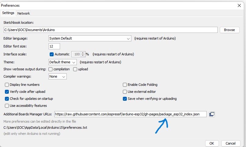
To do programming, firstly i have installed ESP32 Add-on in Arduino IDE by going to File >> Preference >> and add this link https://raw.githubusercontent.com/espressif/arduino-esp32/gh-pages/package_esp32_index.jsonin URL and Click ok.
Open the Boards Manager. Go to Tools > Board > Boards Manager… and Search for ESP32 and press install button for the “ESP32 by Espressif Systems“:
Select your Board in Tools > Board menu (in my case it’s the AI Thinker ESP32-CAM)
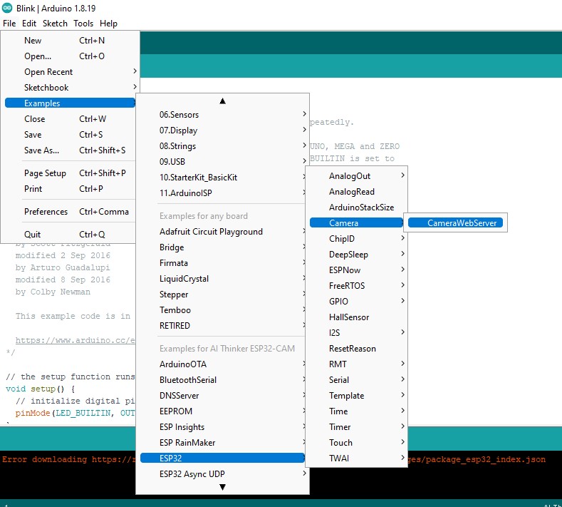
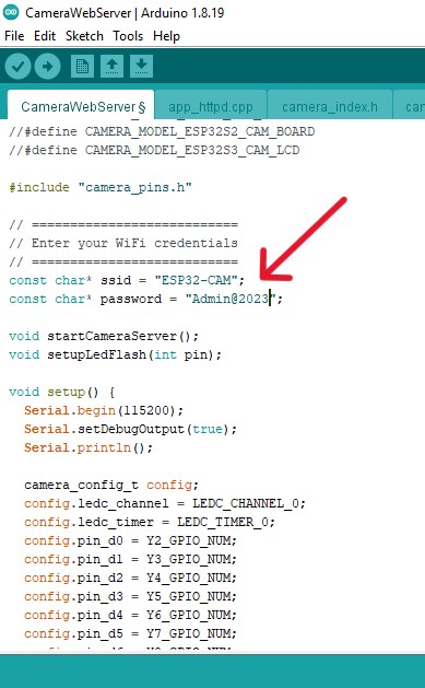
To do programming open the following example under File >> Examples >> ESP32 >> CameraWebServer.
Firstly define your camera module, in my case i have define as Ai Thincker camera module. Then i have changed wifi SSID and Password.
Then I connected the ESP32-CAM to my laptop using a FTDI cable. and uploaded the code.
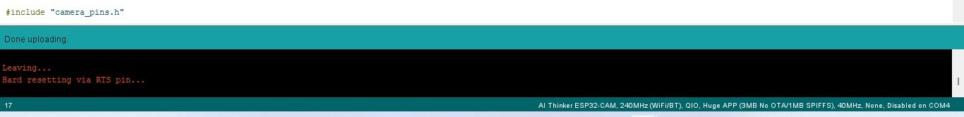
Once the upload is successfully complete, Open the serial monitor, turn the switch on the board, hit the reset button on the ESP. Then you will find your Camera’s Ip address.
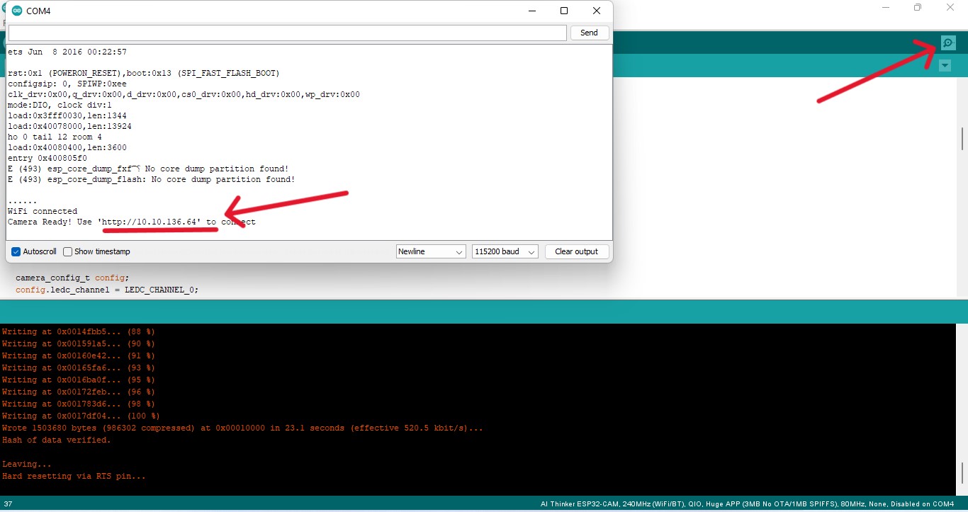
Then copy your IP address and browse in your browser to access the camera
As soon as I got the IP of the Web Camera (10.10.136.64), I typed it on my browser and found my camera module!! After changing the resolution to SVGA(800x600), I hit start streaming and the web cam was working!