Week12- Molding and Casting
Group Assignment
review the safety data sheets for each of your molding and casting materials,then make and compare test casts with each of them
extra credit: try other molding and casting processes
Molding is the process of manufacturing by shaping liquid or pliable raw material using a rigid frame called mold or matrix. For this week, we were required to cast an object or product using the existing mold in the lab as a group project and therefore we used the mold which had an SFL logo.
Group assignment link Here
Individual Assignment
What is Molding and Casting??
Molding is a process that involves shaping a heated material around a mold. The material is then allowed to cool and harden, taking on the shape of the mold. Common materials that are used in molding include plastics, glass, and metals. Casting, on the other hand, involves pouring a molten material into a mold.
Molding is a technique through which a material, often plastic, but also metal, rubber, or powder mixtures is shaped on the outline of a die or mold. There are many different techniques for molding materials, just as there are many different applications for each process. Moulding boxes are special purpose boxes that are designed for use in moulding systems where the demand of high pressure moulding and high production rates (from a fully automated system) require a box designed & machined to exacting tolerances.
Casting is a manufacturing process in which a liquid material is usually poured into a mold, which contains a hollow cavity of the desired shape, and then allowed to solidify. The solidified part is also known as a casting, which is ejected or broken out of the mold to complete the process.
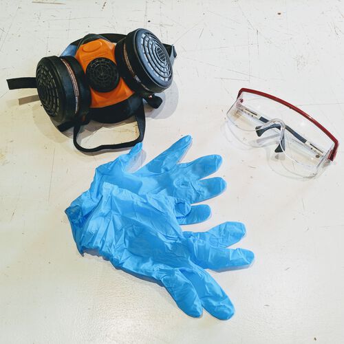
Safety first
In molding and casting week we are going to deal with some less corrosive chemicals but they are harmfull for the body so safety first. Safety gears like glove and safety glasses are a must.
Initially I recommend everyone who works on a casting material to check the Safety DataSheet of the material before using the chemical.
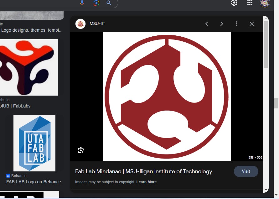
For the molding and casting week, I was thinking to design a simple Fab Academy logo which can be used in my final project (face recognition door lock system).
Fusion 360
Softwares that I Used
Fusion 360
Modela Player 4
Roland SRM-20
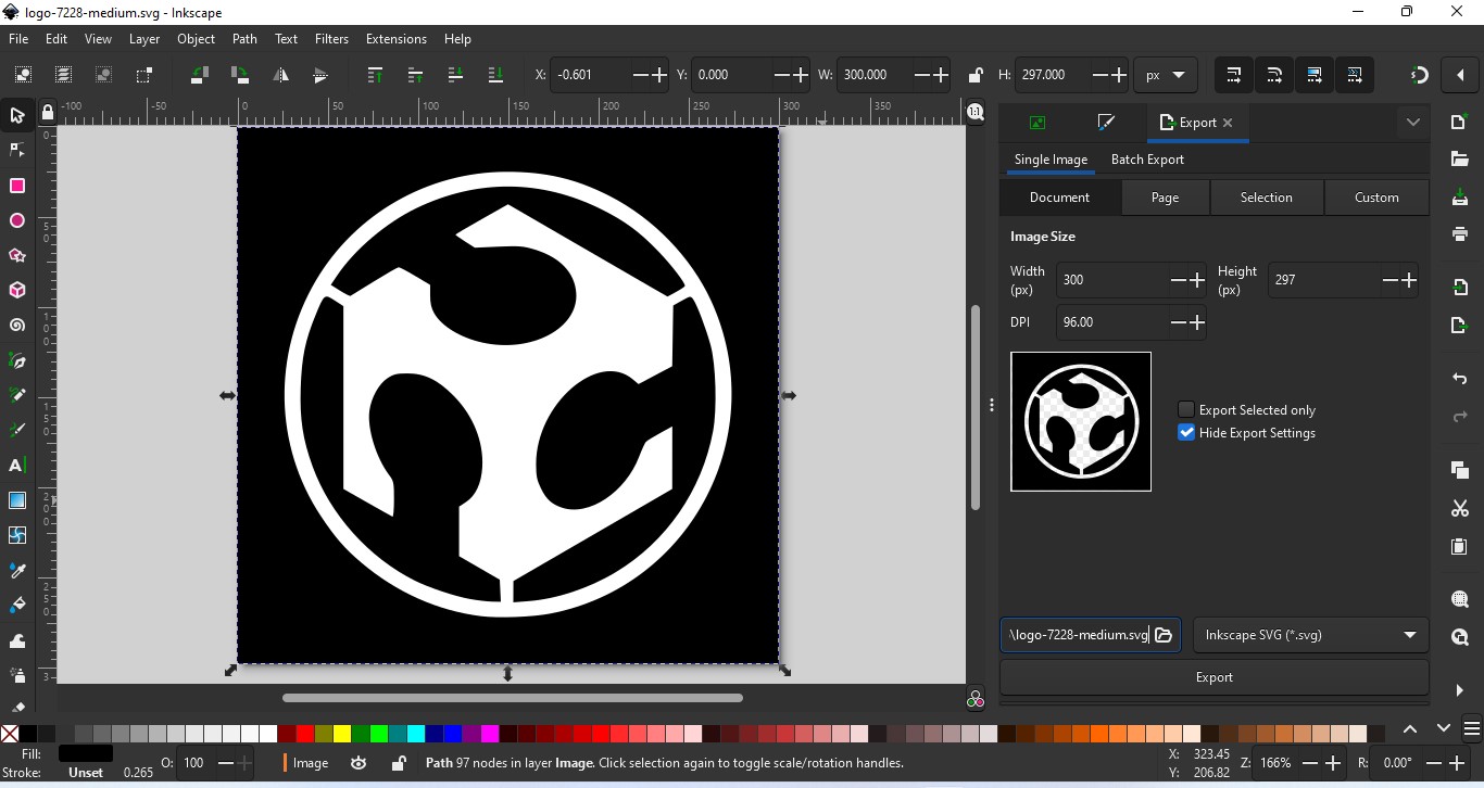
So now i open my Fusion 360 and started with my design as show here: Firstly i have downloaded Fab logo from google in png file formate and done editing in inkscape software.
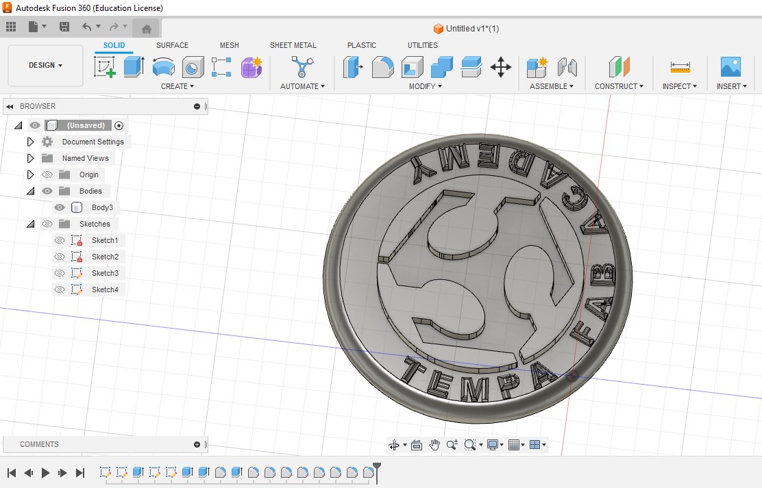
Here is my final design in fusion and then i have exported to stl file.
Design Video
Modela
After completing my design now i started to mill the tool path of my design. So for that i have used Modela Player 4 software.
Workflow
1. Open Your Modela
2. click on file and import your stl file
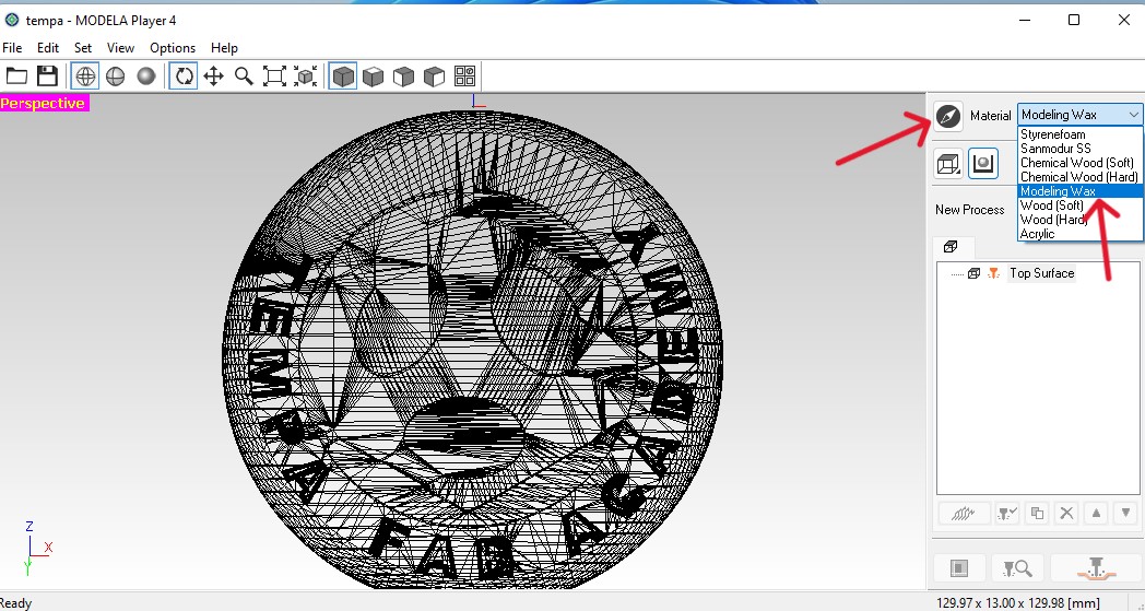
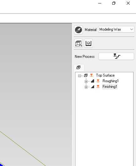
 3. After this chose your material from the top right as Molding Wax
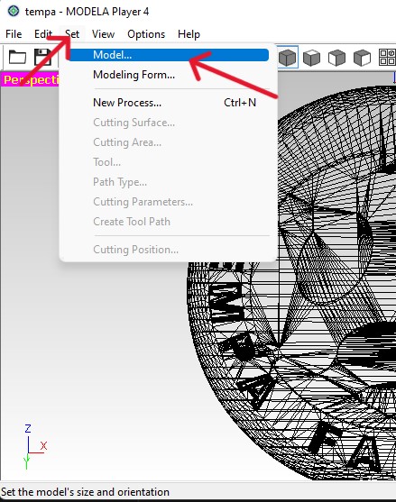
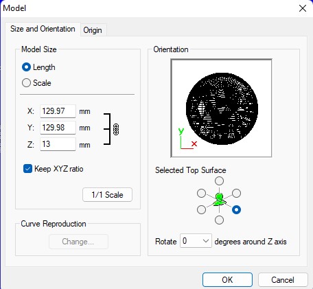
 4. Next click on the model option and check the dimensions of your part as done here.
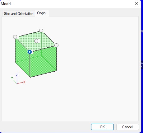
 5. Next click on origin tab, and select your origin as done here
Mill 1: Roughing
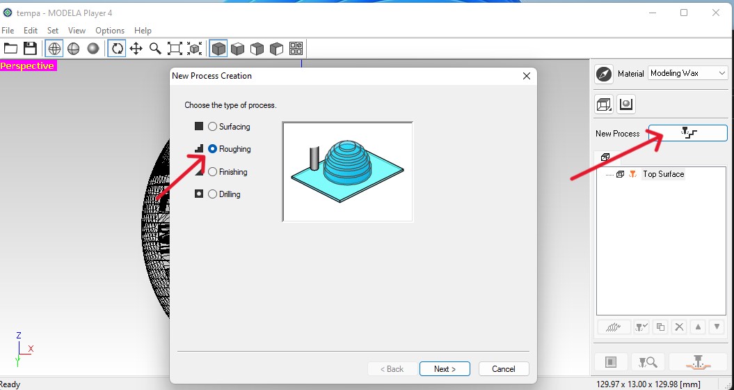
6. Now click on new process option and select Roughing Process >> click next and select the top option.
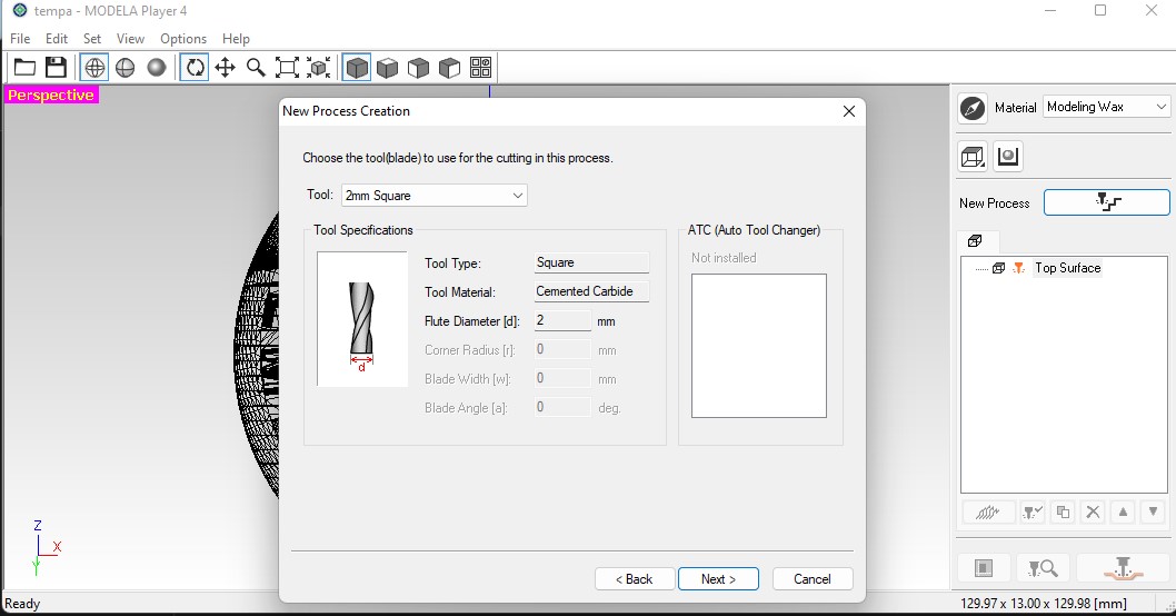
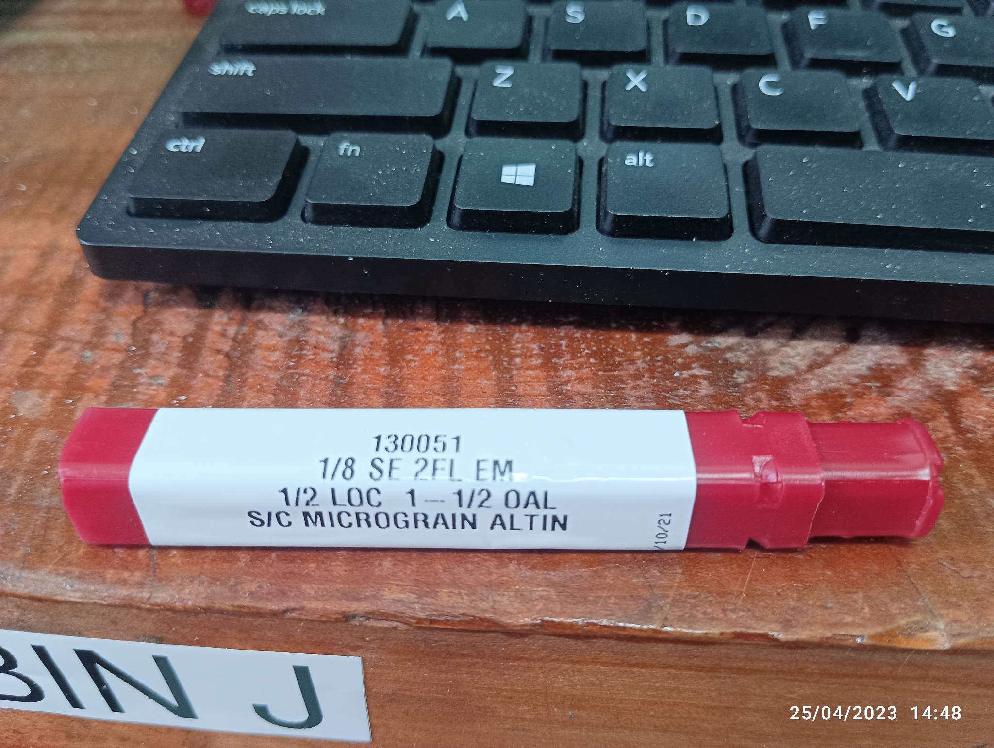
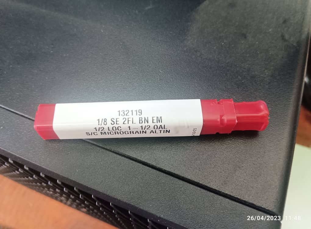
 7. Now Choose the correct Tool size for the roughing as i have done here. So for roughing we will be using 1/8 inch bit
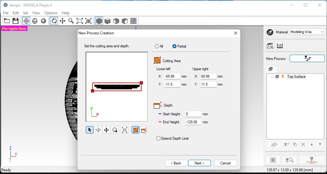
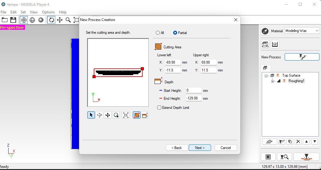
 8. After clicking next, you need to set the cutting and depth as shown below
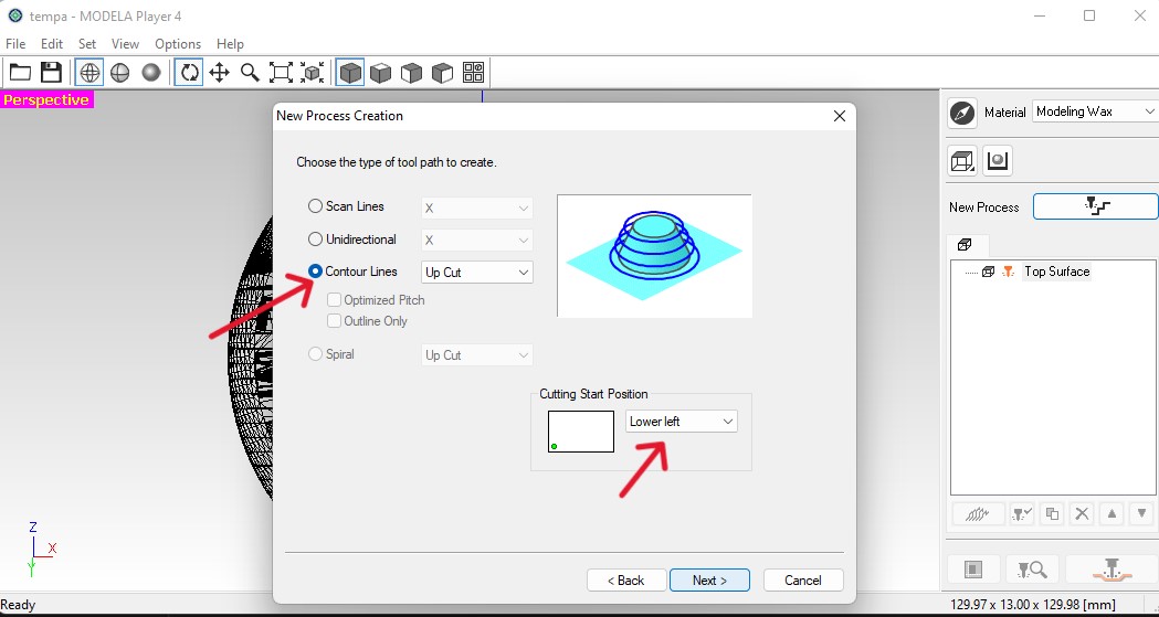
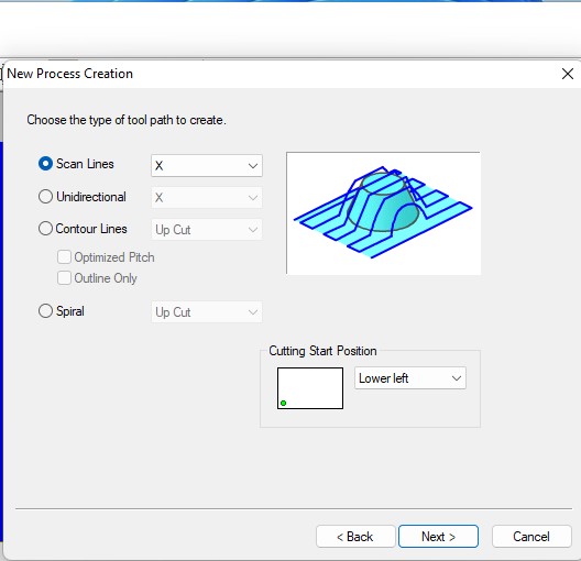
 9. Next choose the type of toolpath and Cutting Start position
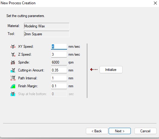
 10. In the cutting parameters,i have set as default setting
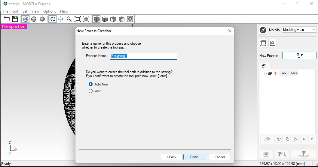
 11. Now save your process with a desired name
Mill 2: Finishing
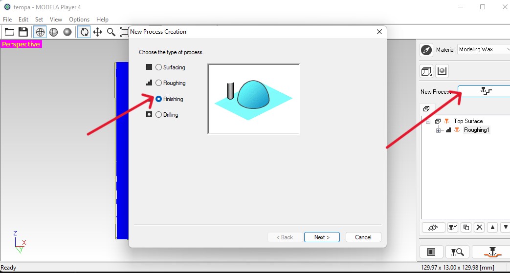
1. Again, click on new precess
2. For finishing, choose finishing and click next
 3. After clicking next, select top option agin
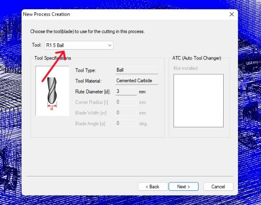
4. For the tool selection, select the R0.5 Ball and click on next
3. After clicking next, select top option agin
4. For the tool selection, select the R0.5 Ball and click on next
 5. For the cutting area and depth section, i have used default as it is for finishing
 6. In choose toolpath, Select scan lines: X with starting position lower left
 7. Set the desired cutting parameters as default and save the process again.
Here is my toolpath:
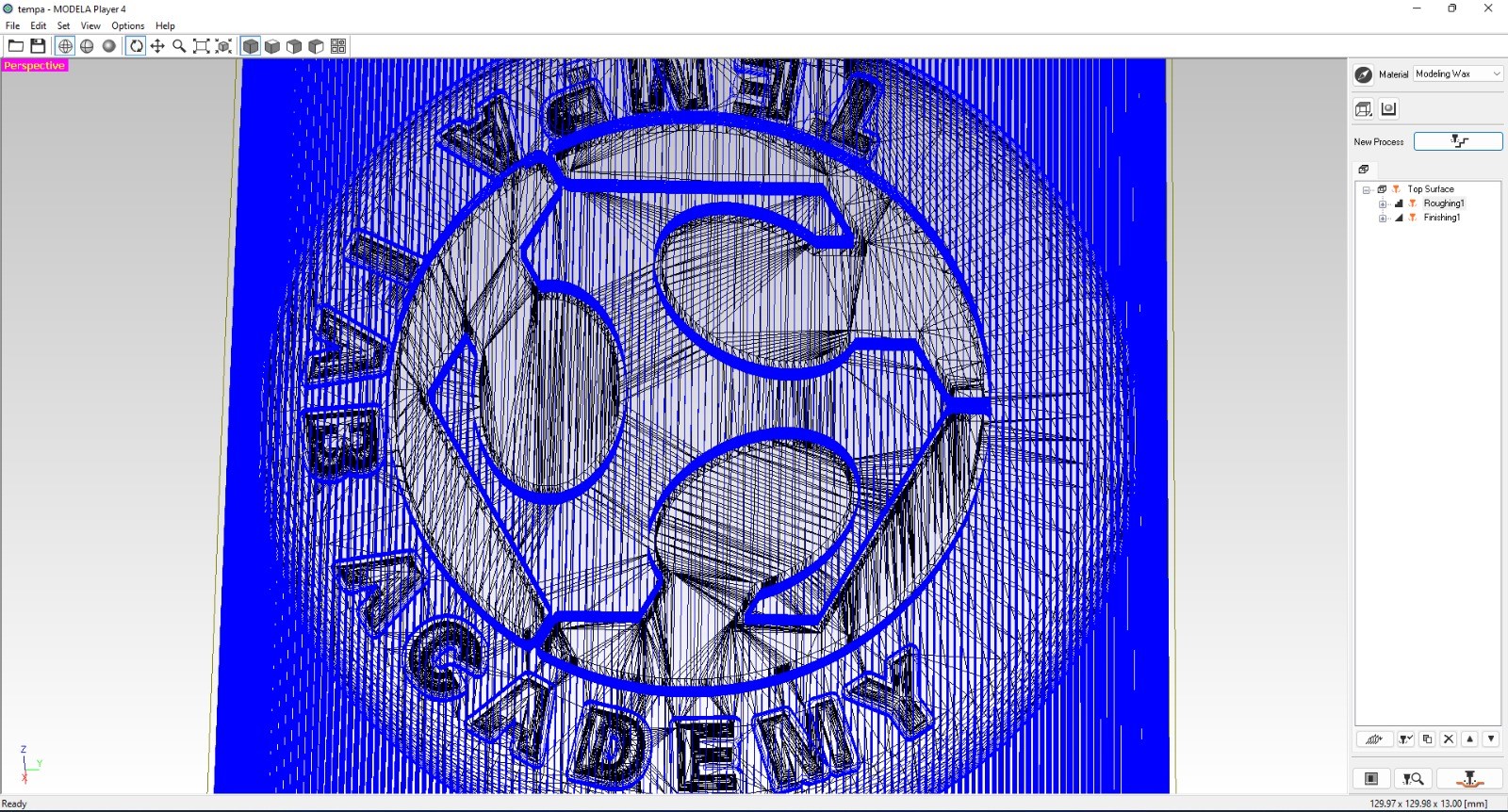
 8. Now you can see the Roughing and Finishing process in the work tree.
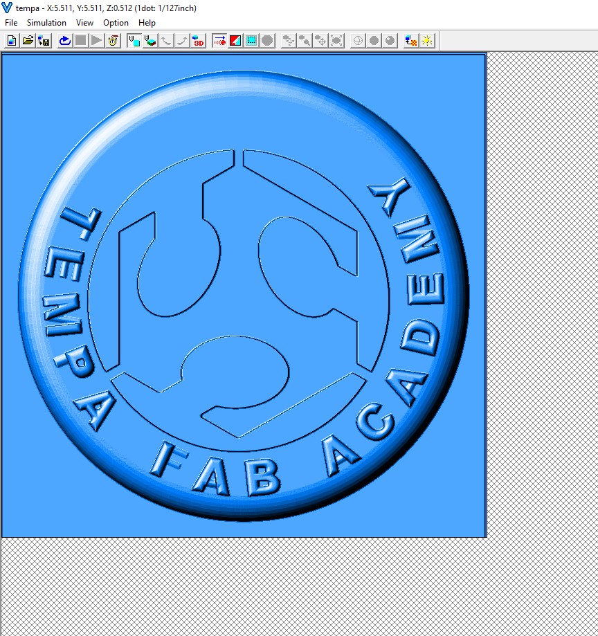
 9. options to view thw preview cutting and Cut-To save the prn file
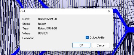
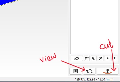 Finally, to save your file click on cut and select output to fil and click ok. Two prn files will be saved
Roland SRM-20 and Vpanel
For milling, Firstly set your wax on the top of works space with using double tap.
Set your XY origin form vpanel, in my case i have set the XY at the left bottom conner.
Insert your 1.8 milling bit and set the Z on vpanel
Then go to cut >> deleted previous file >> add your roughing.prn file and click on output so that milling will start
Once the Roughing is done. take the bit to the XY origin in Vpanel.
Then now remove your bit and insert 1/8 BN bit
Result 1
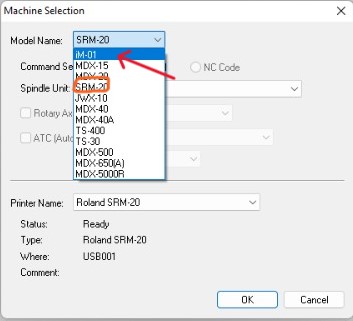
My wax was not good and i have done mistake to change the machine setting.
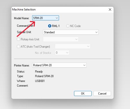
Then I ask help from our guru Zina, as she recommend me to chang the machine setting to SRM-20 in Modela. Befor i was using iM-01 so i changed to SRM-20.
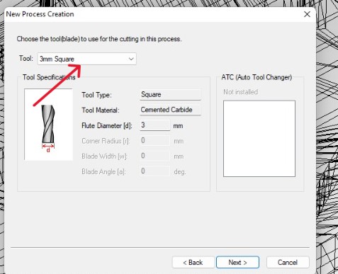
 After this changes i agin began to set the roughing tool as 3mm square and Finishing as 1.5 ball for my design in correct settings
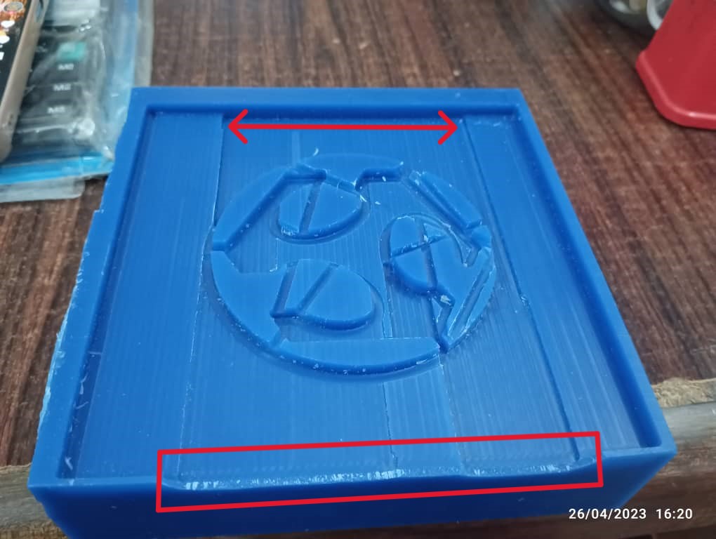
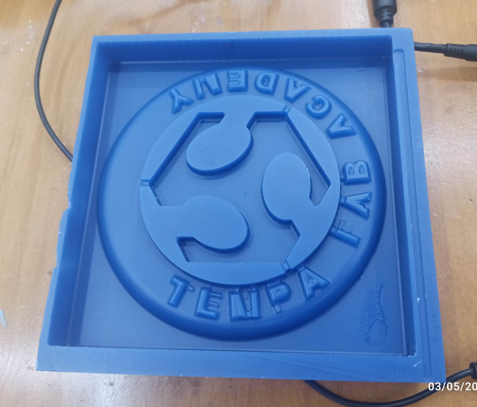
 After doing second time milling, my result:
Molding
To make a mold we have two different types molding material (SORTA-CLEAR TM 37 and OOMOO TM 25). So I want to use OOMOO TM 25 for my model.
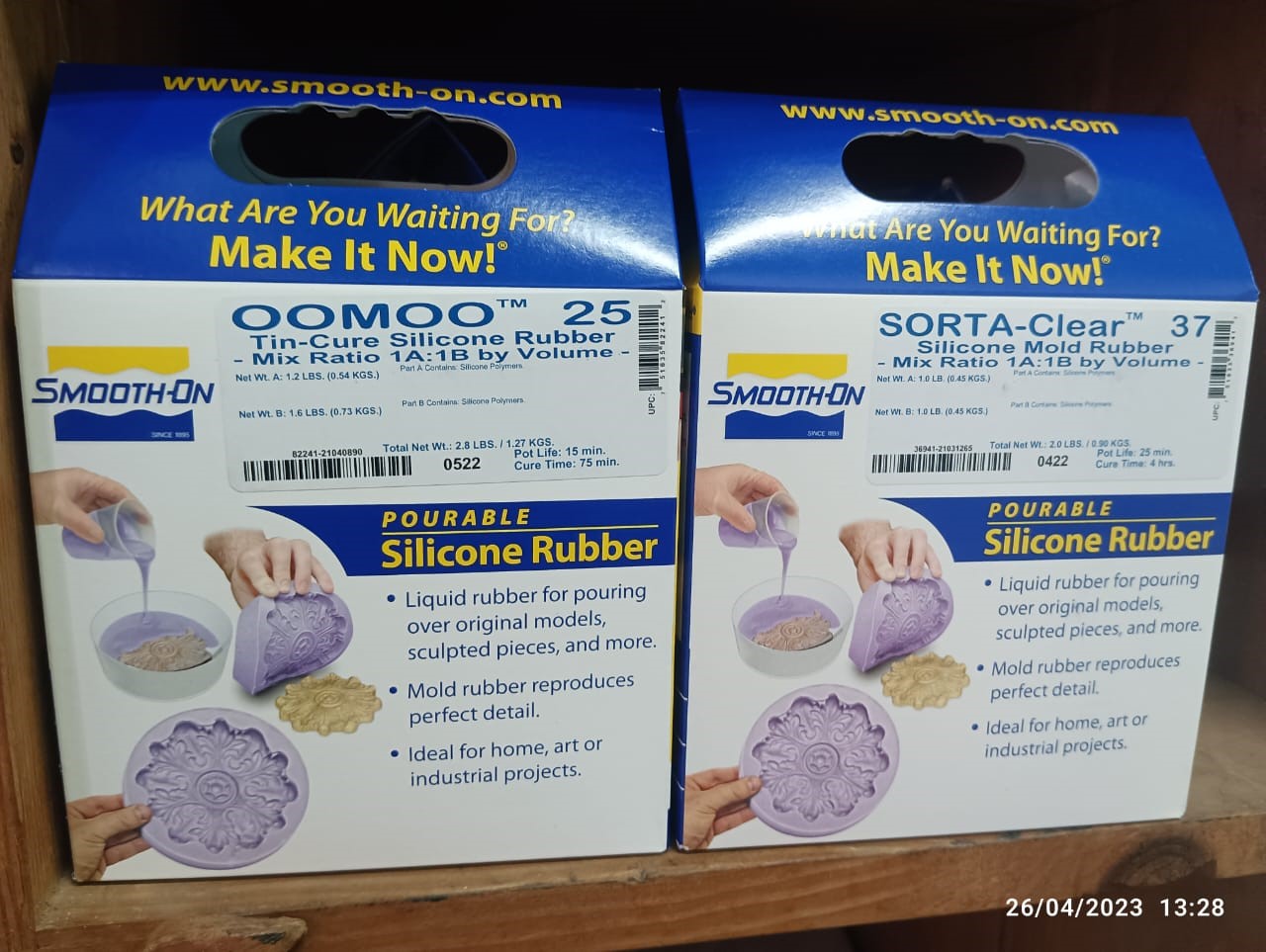
So firstly I went through Datasheet/information of this product Oomoo 25.
Oomoo 25 Workflow
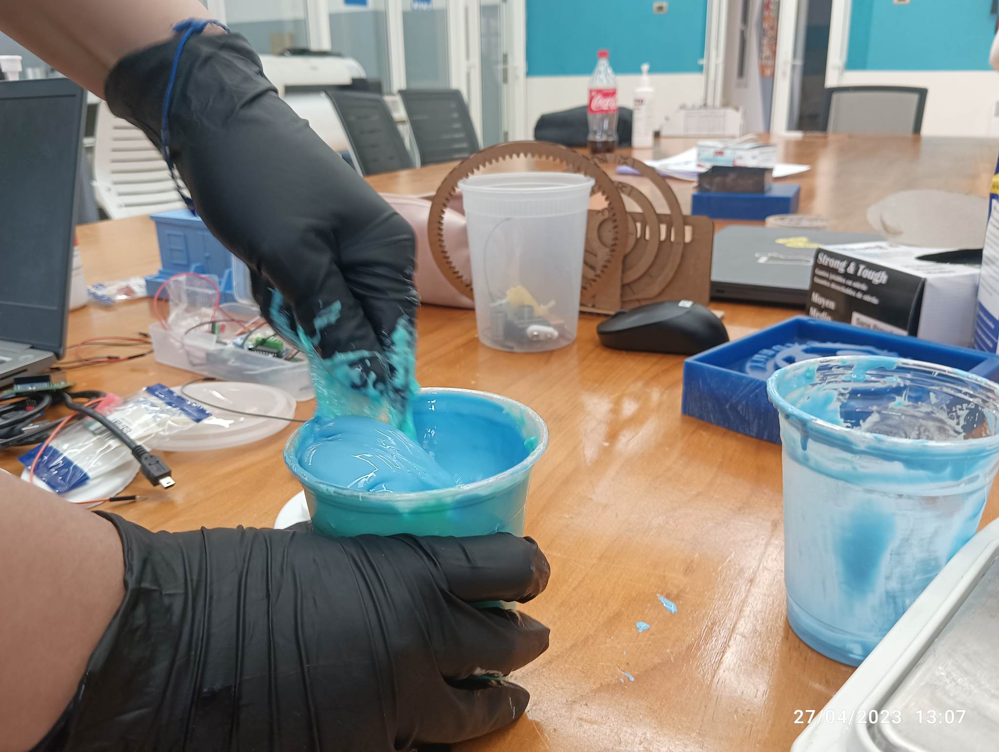
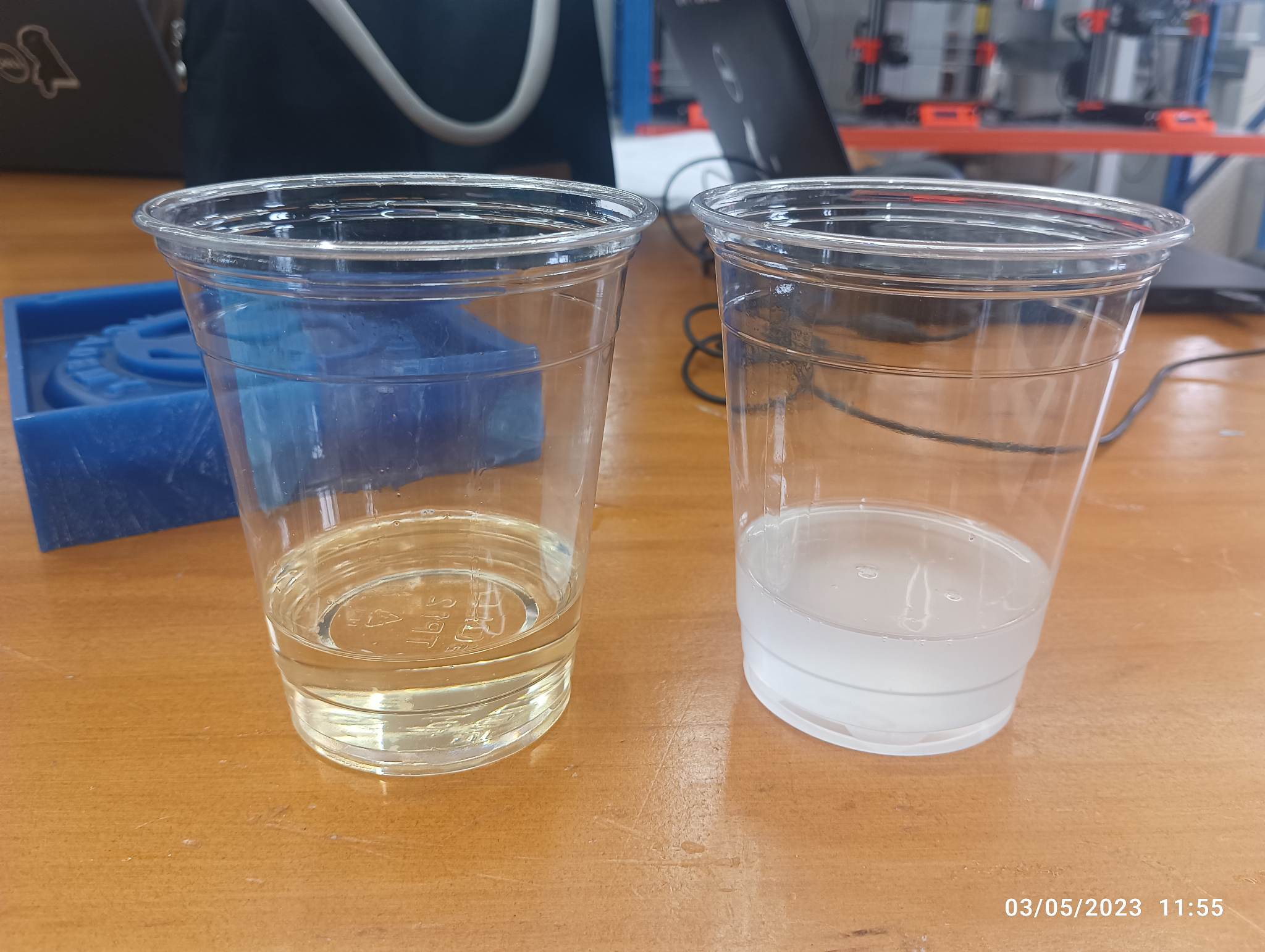
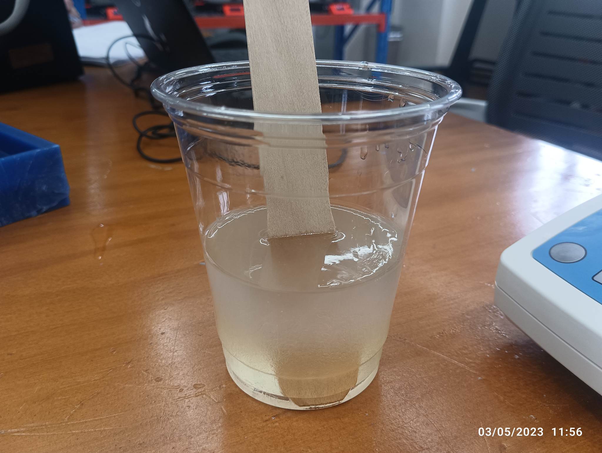
Firstly I thoroughly stirred both liquids (Part A and Part B) individually with a wooden stick.
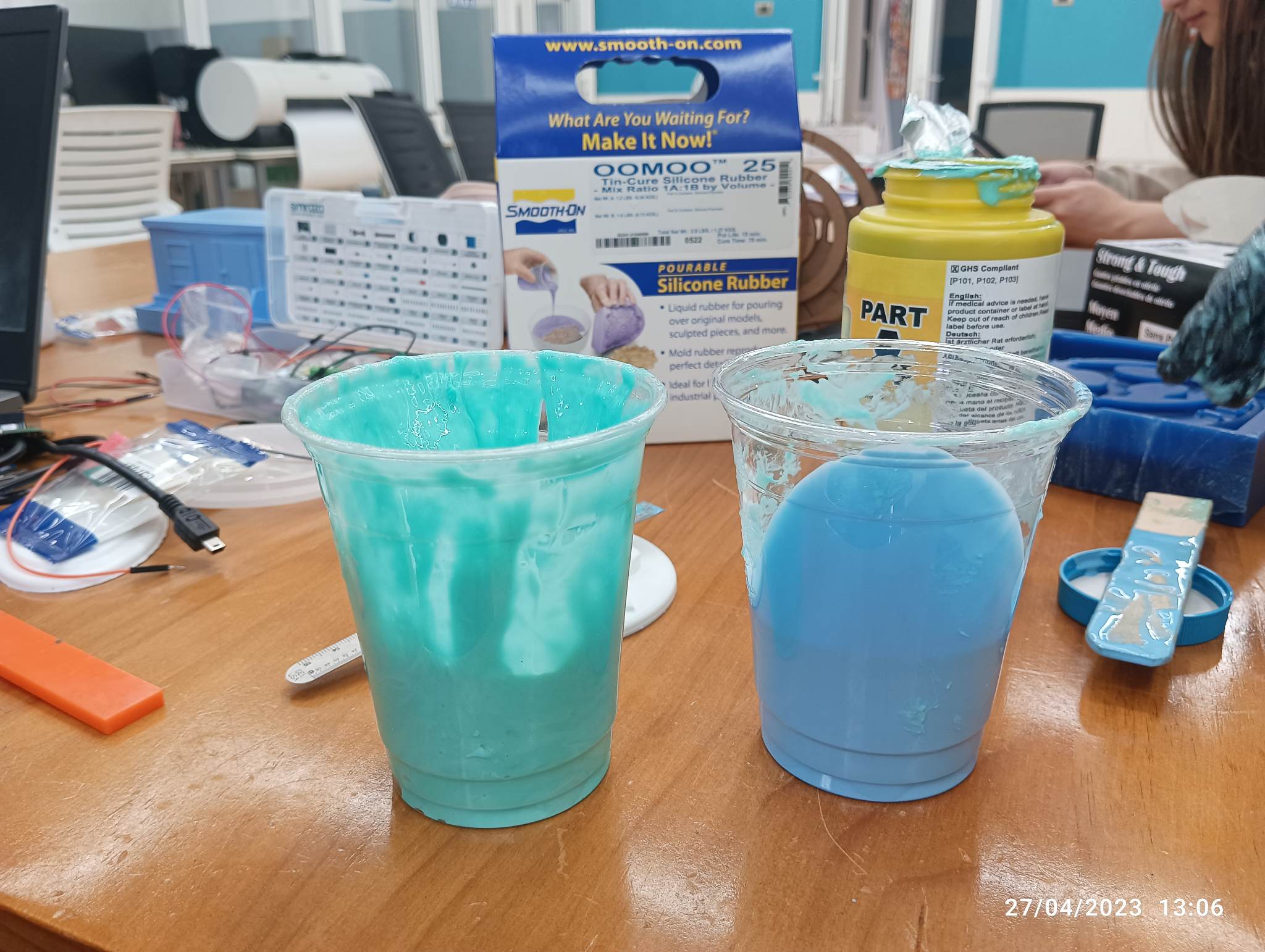 After that, I poured both liquids into a single cup and mixed them well to mixed properly.
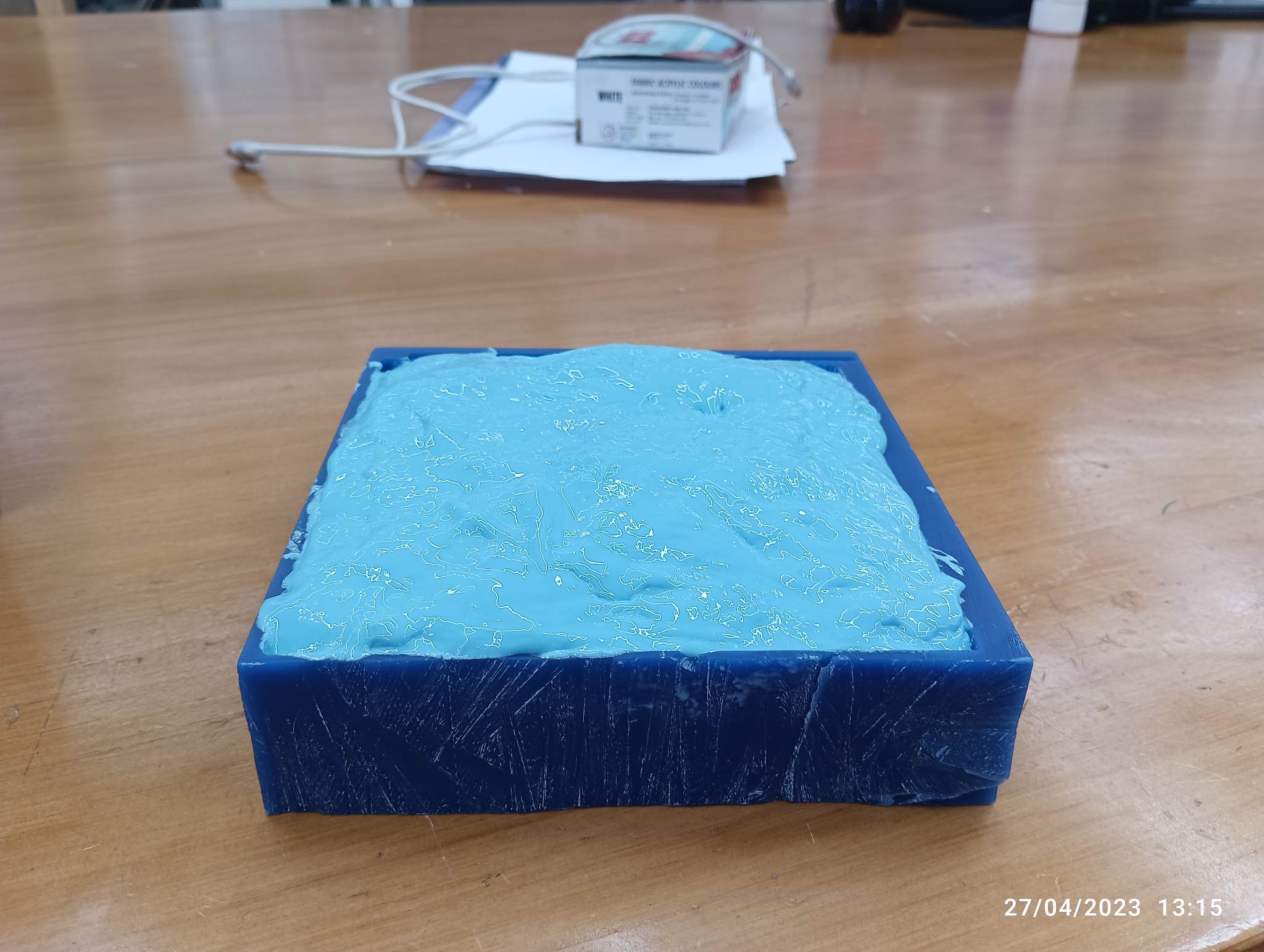
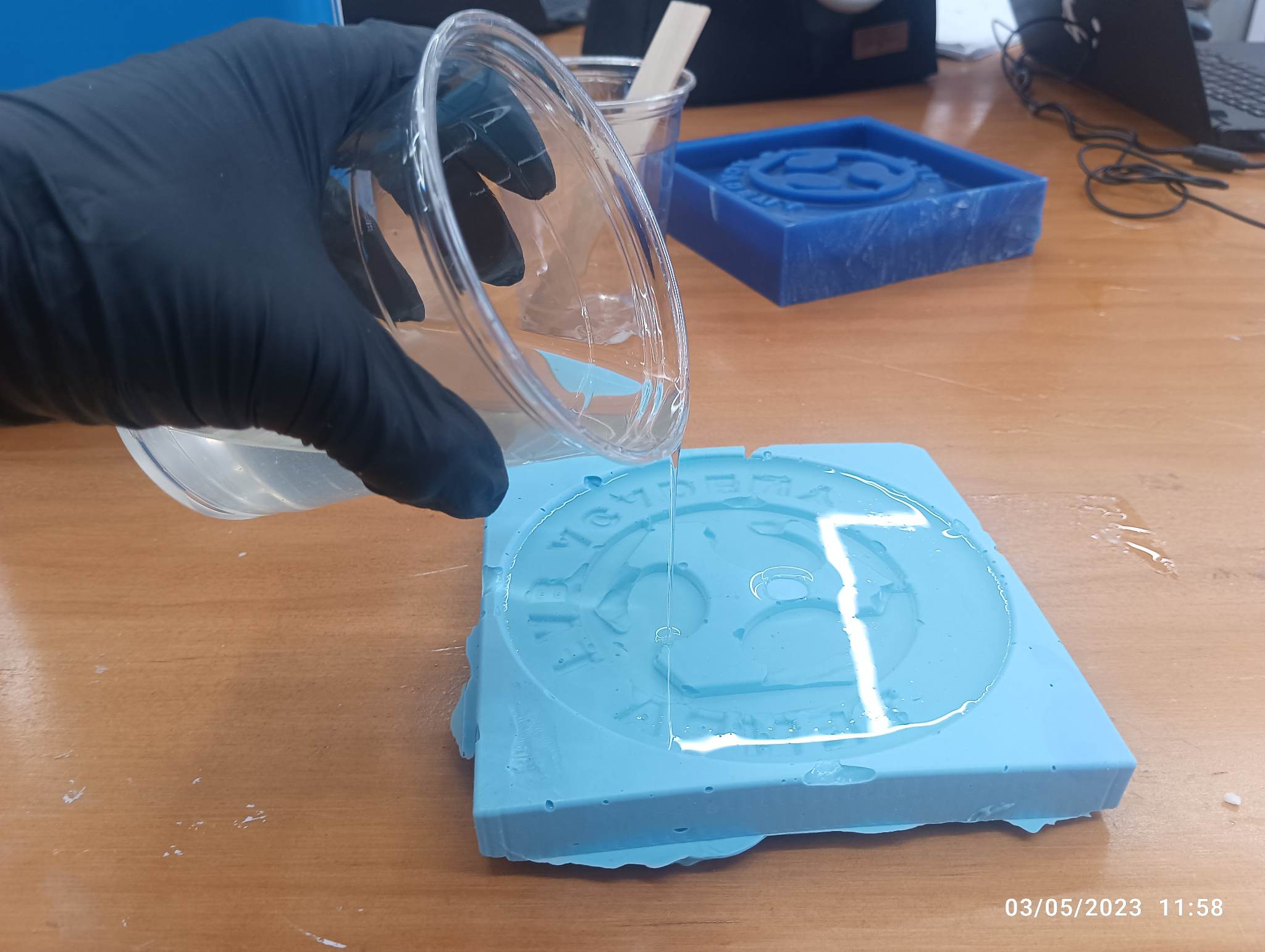
 After mixture is complete, I poured it onto my positive wax mold and let it sit for few hours
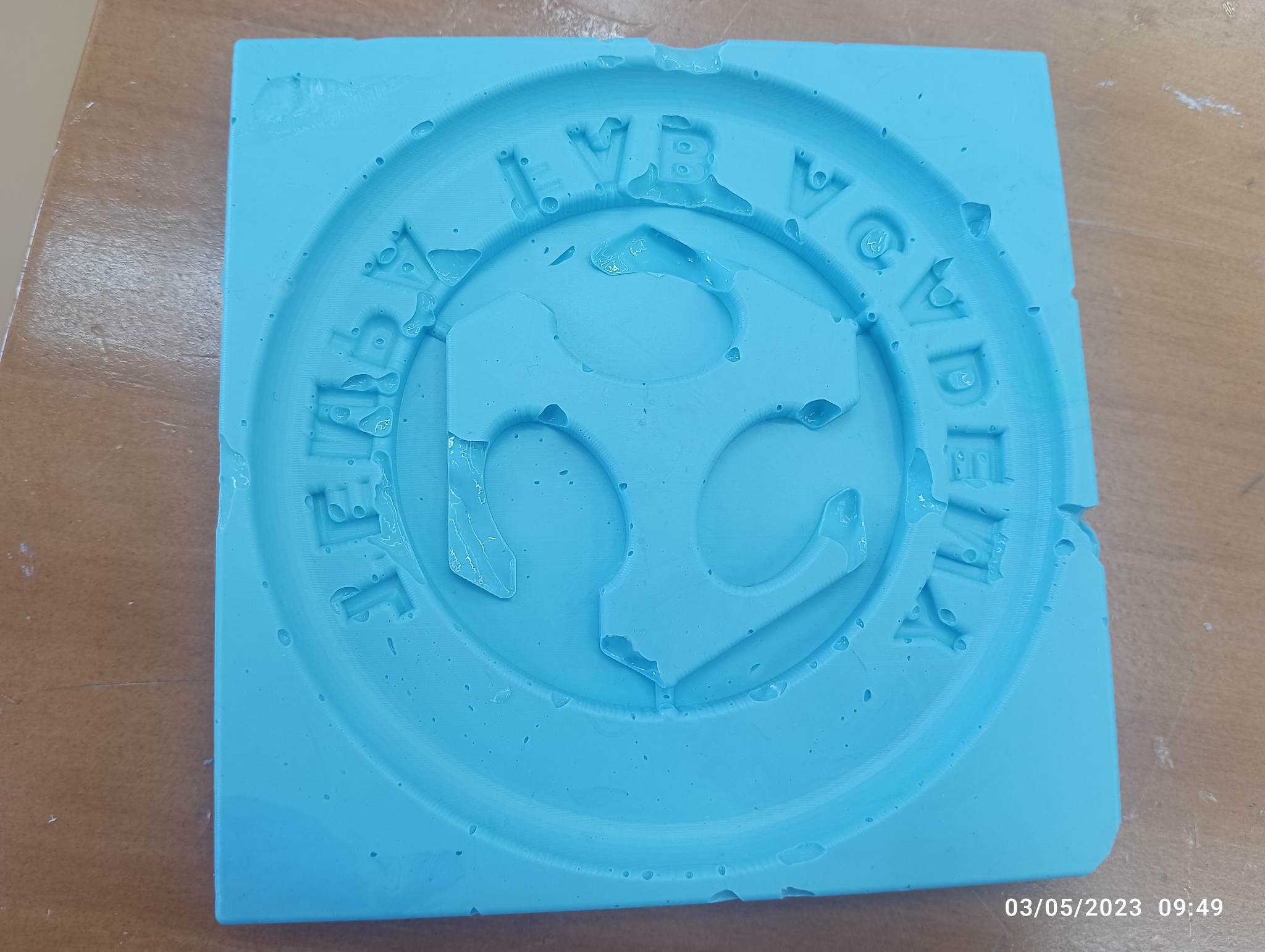
Here is my Negative Rubber Mold:
Casting
For casting, In our lab we have only options Smooth-Cast 305. So I decided to use this for casting.
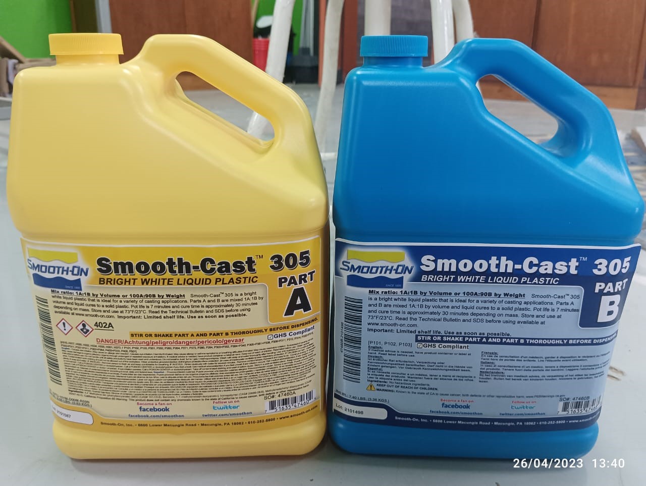
Firstly i began with its Datasheet/Information
As Mr. Kencho (CNR fablab) mention, I weighed out two equal parts in volume (Part A 7 Part B) of the smooth cast and then mixed them together
 Then I poured it into the negative silicon mold and let it sit for 50 mins to 1 hour.
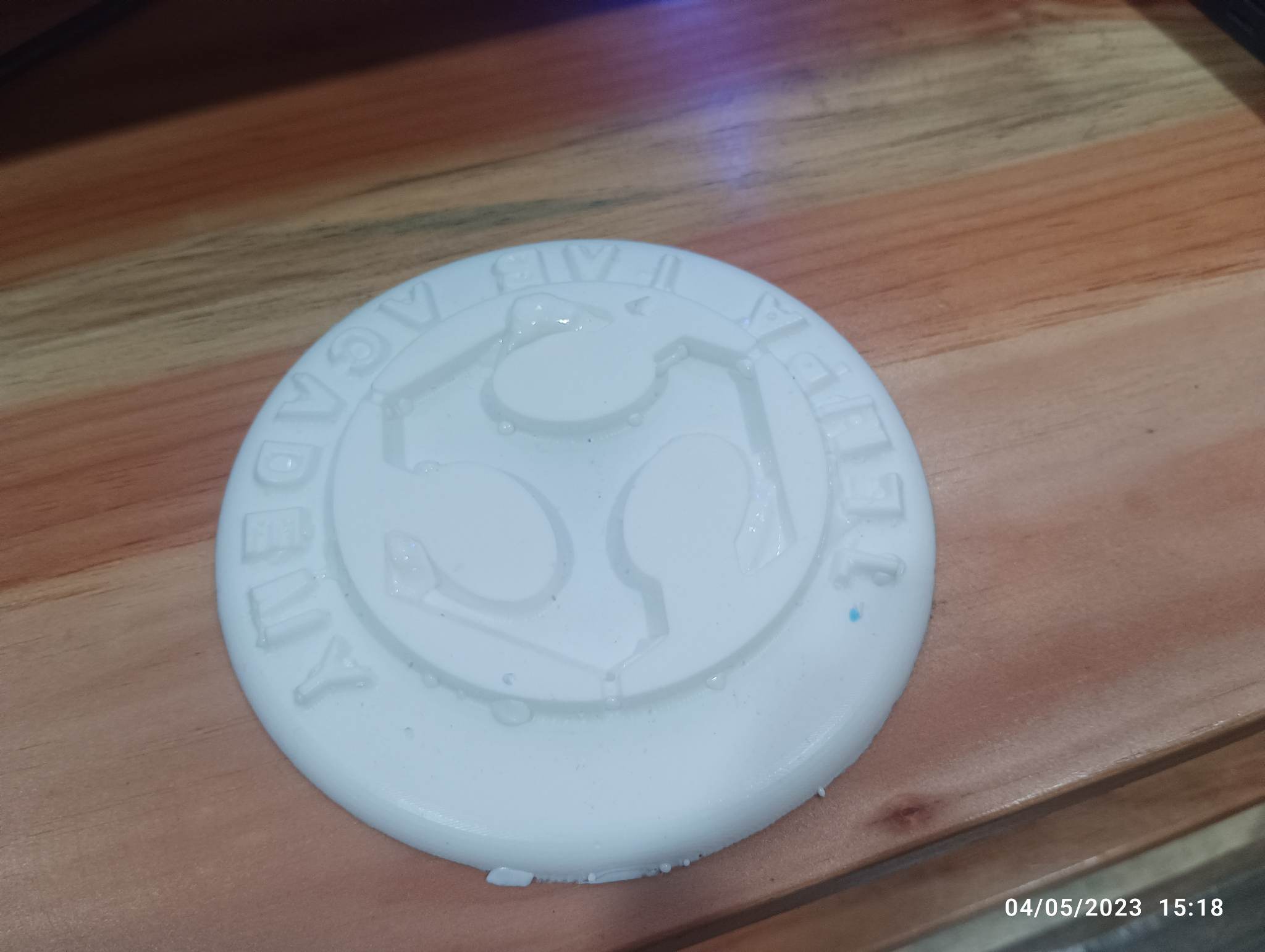
what went wrong in casting??
During casting, I poured silicon on my product and there was some air bubbles forming within the casting material and my product result was voids or defect.
In casting it need specific temperature rage for optimal performance so in our lab the temperature was too hot and it causes premature solidification.
Product
what did you learn from this unit?
Here are some that I have learned from the field of molding and casting:
1. Materials and Techniques: Molding and casting involve working with a variety of materials such as metals, plastics, ceramics, and composites. Understanding the properties, behaviors, and appropriate techniques for each material is crucial for achieving successful results.
2. Mold Design and Preparation: Proper mold design, including considerations for parting lines, draft angles, gating systems, and venting, is essential for obtaining high-quality castings.
3. Process Optimization: Molding and casting processes can benefit from optimization techniques. This includes identifying and addressing potential issues such as air entrapment, shrinkage, warping, or surface defects.
The differences from 2.5D and 3D milling
2.5D milling and 3D milling are two different approaches to CNC (Computer Numerical Control) machining processes. While they share similarities, there are distinct differences between the two techniques. Here is an explanation of each:
1. 2.5D Milling:
2.5D milling, also known as 2.5-axis milling, refers to a CNC machining technique that operates primarily in the X, Y, and Z axes.
It involves machining flat or shallowly curved surfaces, typically with vertical walls, using a cutting tool with a specific diameter.
The tool moves along the X and Y axes to cut out the desired shape, while the Z-axis controls the depth of the cut.
2.5D milling is ideal for creating simple, two-dimensional parts or features on a three-dimensional object.
The technique is commonly used for cutting pockets, slots, holes, and engraving operations.
2. 3D Milling:
3D milling, also known as 3-axis milling, is a CNC machining technique that operates in the X, Y, and Z axes to create three-dimensional shapes and surfaces.
It involves machining complex, contoured, and sculpted surfaces using a variety of cutting tools, including ball-nose end mills and tapered end mills.
3D milling can produce intricate details and complex geometries with smooth and flowing contours.
The tool moves along the X, Y, and Z axes simultaneously, allowing it to follow the contours of the object and remove material accordingly.
This technique is commonly used for creating molds, dies, complex parts, artistic sculptures, and organic shapes.
Design File
STL File
Fusion File