
Week 04 - Embedded Programming
This week introduced us to embedded programming, in other words, how to program electronics to do what we want. We started off with some basics about computers and the way they function, bits and bytes here and there to get our knowledge going. I had very brief background about an Arduino and how to turn on an LED, however, we used different boards with different processors but with the same logic.
Getting Started with Our Boards
We were provided with a Barduino 3.0 (which is the Barcelonian version of an Arduino) to do the assignments and learn how to code it. We were told that it is a development board, which means that it is a complete, pre-designed circuit that provides an easy way to experiment and prototype new electronic designs.
The main differences between an Arduino and a Barduino are the microcontroller chipset, and the pin layout… technically everything. The Arduino's microcontroller was 'ATmega328P' and the Barduino had an 'ESP32' and 'ATSAMD11C14A' microcontrollers. This required us to download extra boards (board definitions) from the board manager in Arduino IDE to be able to communicate with the Barduino. Oh! also, we downloaded Arduino IDE, which is a software application used to write, compile and upload code to Arduino microcontroller development boards. Please check the heading 'Individual Assignment' below for the steps I took to program the Barduino.
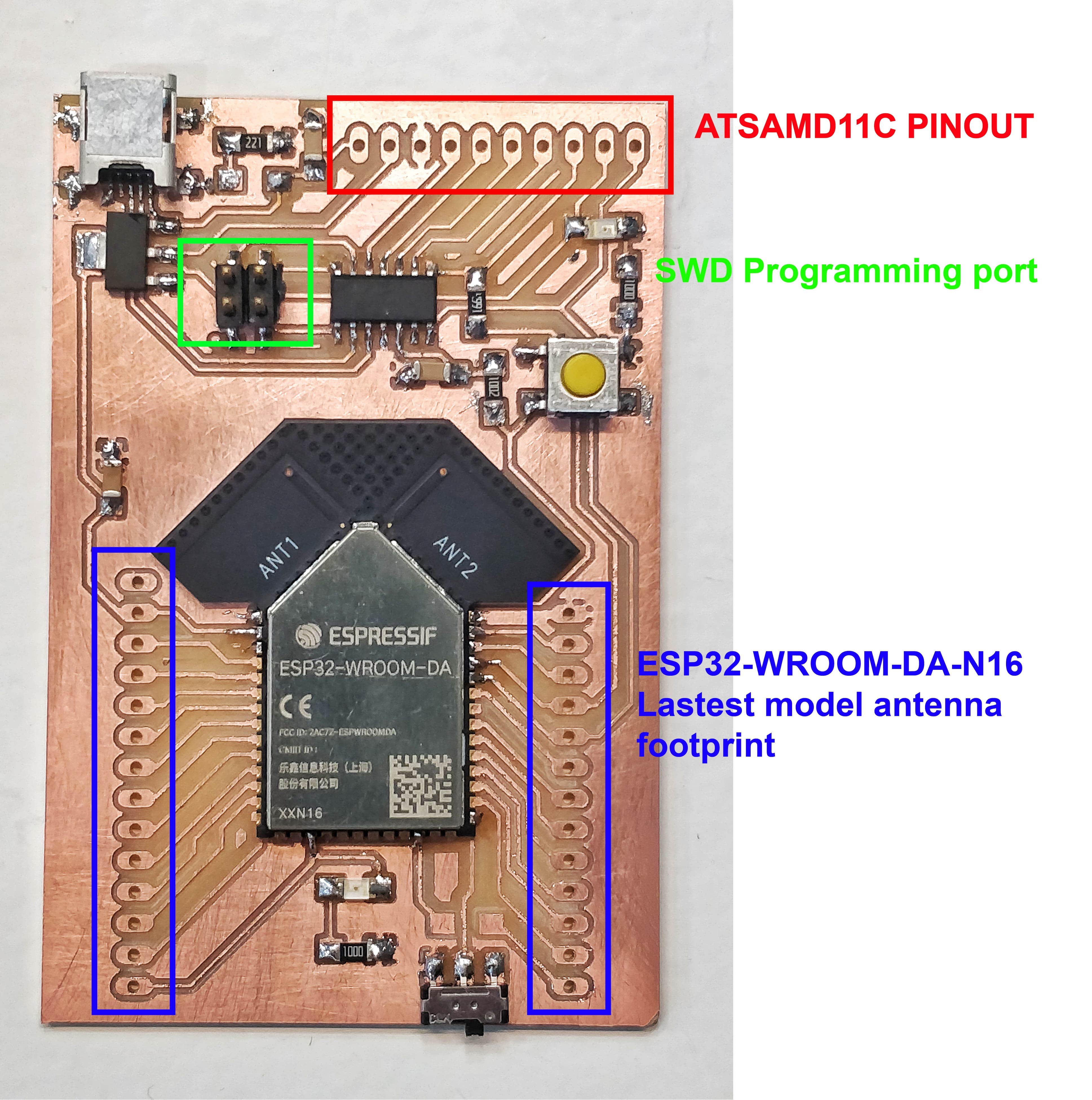
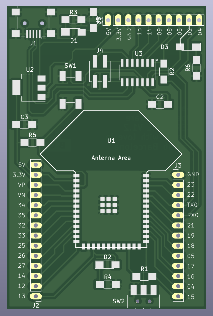
Also, the Barduino looks like that, yup, I told you… it is a development board indeed, it's the inside what matters. To be fair, the ones we currently have look nicer.
Group Assignment
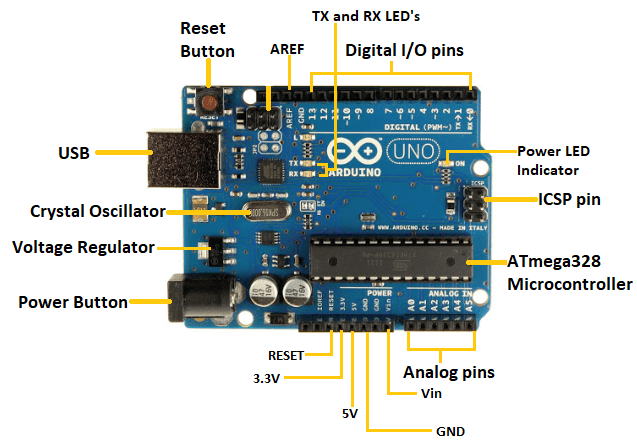
For this part of the assignment, my role was to study the architecture of the Arduino board and talk about its architecture compared to the esp32 microcontroller. The Arduino has an Atmel AVR microcontroller. The architecture of the Arduino board is based on a Harvard architecture, which means that the program memory and data memory are separate and accessed using different buses.
In general, some of the advantages of the Arduino over the esp32 are:
- It is beginner-friendly with a simple programming language and development environment.
- It has a huge and supportive community with plenty of resources to help beginners and experienced developers.
- Arduino boards come in different sizes and designs for various applications.
- It is open source, allowing for high customization and flexibility.
You can check the more in-depth explanation over our group website.
The following image shows a detailed view of the Arduino board.
Another thing that got my attention with Arduino are the Arduino Shields. They are modules that can be plugged onto an Arduino board to provide additional functionality or features. They are typically designed to fit onto the standard Arduino pin layout and can be easily added or removed from an Arduino board. Examples of shields include sensors, communication modules (like Wi-Fi or Bluetooth), motor drivers, and LCD displays. Arduino shields make it easy to add complex features to an Arduino project without having to design custom circuitry or write low-level driver code. Also, they shields come with their code libraries too which makes it super easy to use.
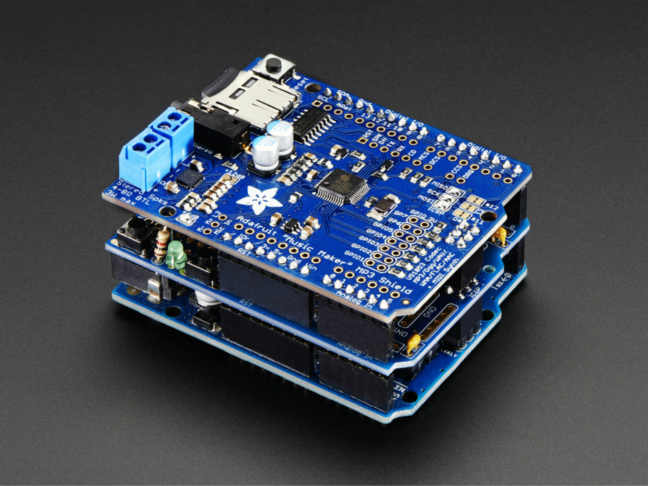
You can click here for more shield options in Arduino's official website.
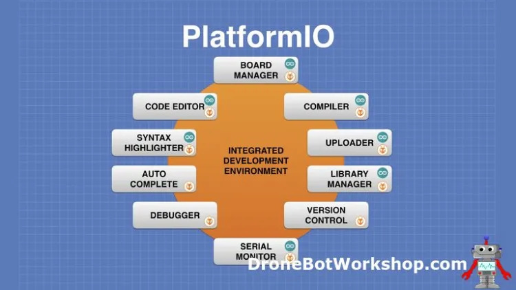
Moving on, I have checked PlatformIO which is very similar to Arduino IDE but is a more advanced and powerful ecosystem for embedded system development than Arduino IDE, with support for multiple platforms and an easier way to manage libraries and dependencies. However, Arduino IDE is simpler and easier to use, making it a good choice for beginners or simple projects.
Both Arduino IDE and PlatformIO have extensions on VSCode, the advantage of PlatformIO over Arduino IDE is that it has an integrated debugger. The following image shows the similarities and differences of both software. By the way, the new version of Arduino IDE has the autocomplete feature.
At the end of the day, I will stick with Arduino IDE since I have it already installed, and we are using it at the academy. Plus, I am planning to continue using Arduino platform for good, I will switch to PlatformIO whenever I reach the capability limits of the Arduino IDE.
Individual Assignment
Microcontroller Data-sheet
Going through datasheets looks very smart but do we actually understand what's going on? I have gone through datasheets before but not for microcontrollers. I have only been through the datasheets of simple electronic components which typically have tens of pages, which is few compared to microcontroller of hundreds. I have watched two YouTube tutorial videos by MicroType Engineering and Sayanee Basu on the best practices of going through a datasheet. With the right methods, I have found that it is really helpful to understand these datasheets in the case of building our own custom circuits, because they literally provide everything, even the mechanical dimensions of the IC's. However, if the microcontroller or any electronic component was being used on a development board, well… the datasheet would definitely help too.
From the videos that I have watched, I followed the following steps to go through and learn the SAMD11 Datasheet:
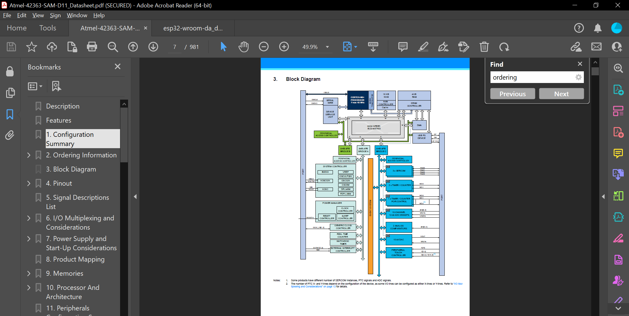
- The first step I did was to look for the open schematic, it gives a very good overview of the microcontroller.
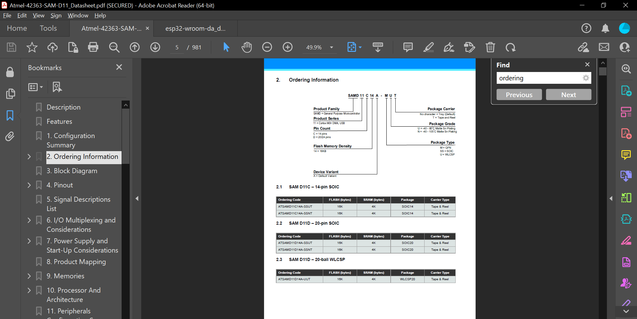
- Then I have checked the ordering code, or sometimes called ordering information, and this gives the following details of a microcontroller: Model Number / Package Type / Pin Count / Speed Grade / Temperature Range. For the SAMD11, here are the following details:
- Model Number: SAMD11 General Purpose Microcontroller - 16 KB of flash memory, 2 KB of SRAM
- Package Type: SOIC14
- Pin Count: 14 Pins
- Speed Grade: Up to 48 MHz, depending on the clock frequency set by the user
- Temperature Range: -40°C to 85°C
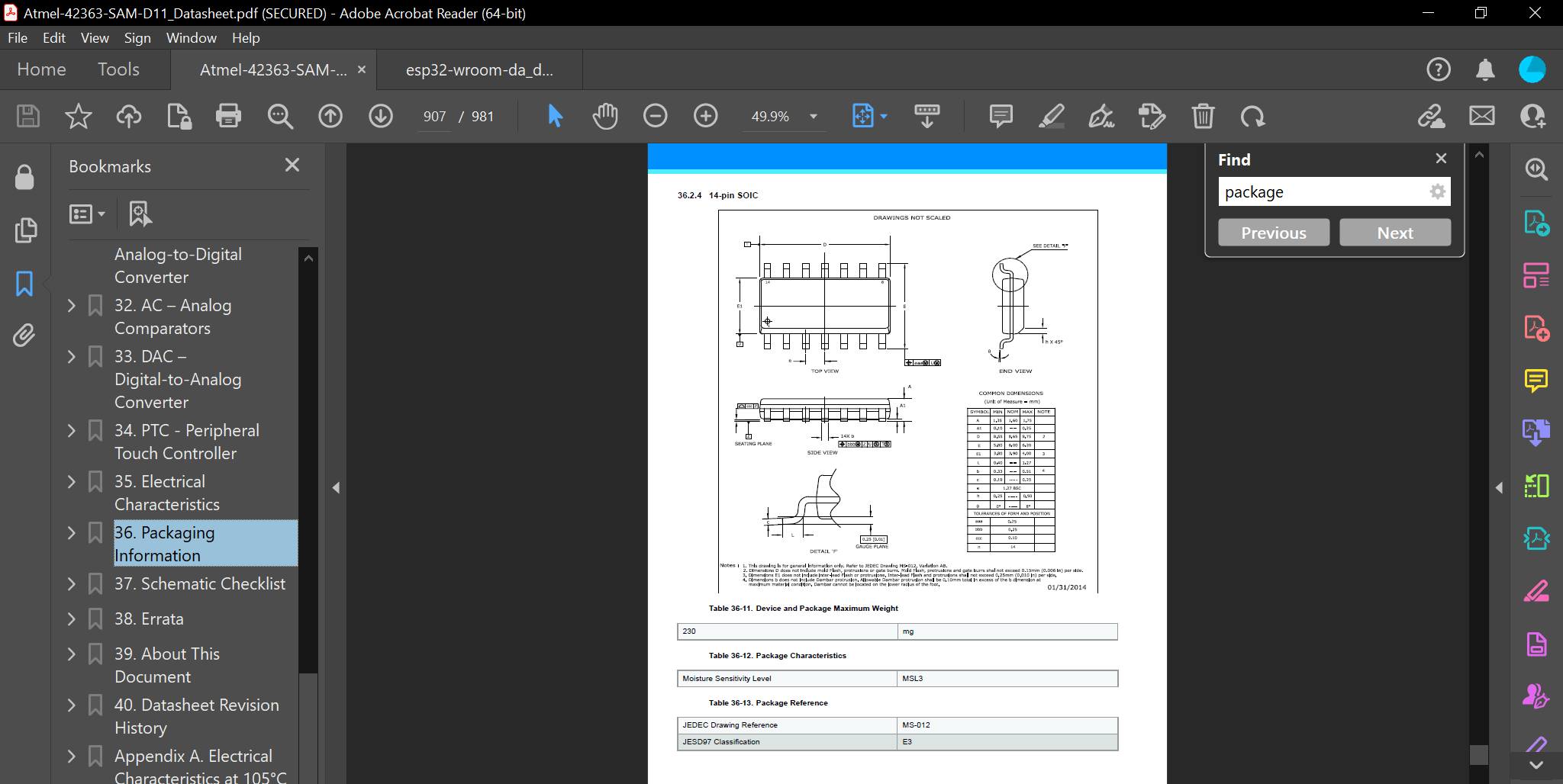
- Afterwards, I went to check the packaging information, or sometimes called the mechanical packaging. In a nutshell, it shows the physical dimensions of the microcontroller or whatever component you are looking for. This comes in handy when we want to design our own boards. Since there are many variants of the SAMD11 chip, I looked for the one with the 14 pins which matched what we had.
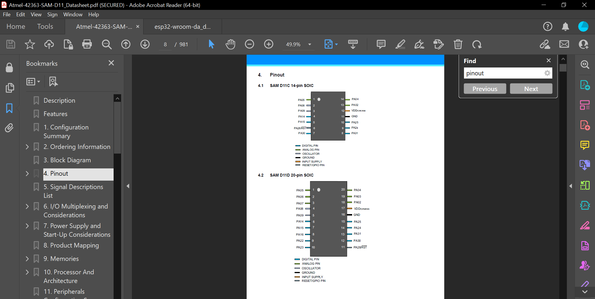
- In this step, I looked for the pinout of the microcontroller in which it showed the physical layout and function of each pin or terminal on the microcontroller. It usually shows the pin number, pin name, pin type, pin function, and pin description. Again, I looked for the 14-pin variant.
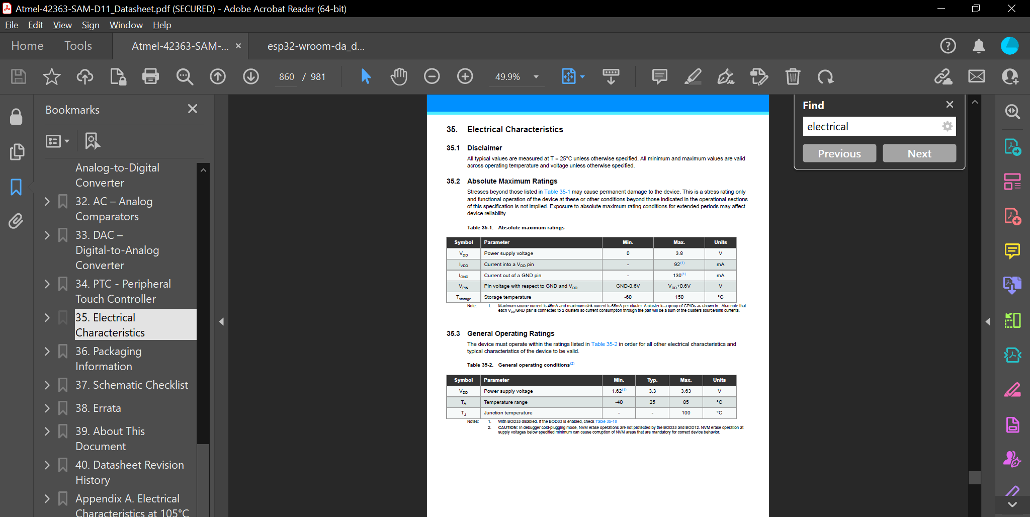
- Moving on to one of the most important things to look for, which was the electrical characteristics, or sometimes known as power characteristics or electrical specifications. It showed me the absolute maximum rating and the general operating rating. For the SAMD11, the absolute maximum rating was VDD= 3.8V, anything higher than this will bust the microcontroller. The general operating rating ranged between 1.62V to a max of 3.63V, and the typical voltage falls around 3.3V. From my understanding that the microcontroller won't get damaged if it ran up to 3.63V, but it's not recommended. As a safety measure, we can add a limiter to limit the voltage to 3.5V for example, and this ensures the safety of the microcontroller.
I still don't understand everything of what the above information entail, but that's how we all start.
For reference, I also checked the ESP32 Datasheet.
Programming the Microcontroller
Software
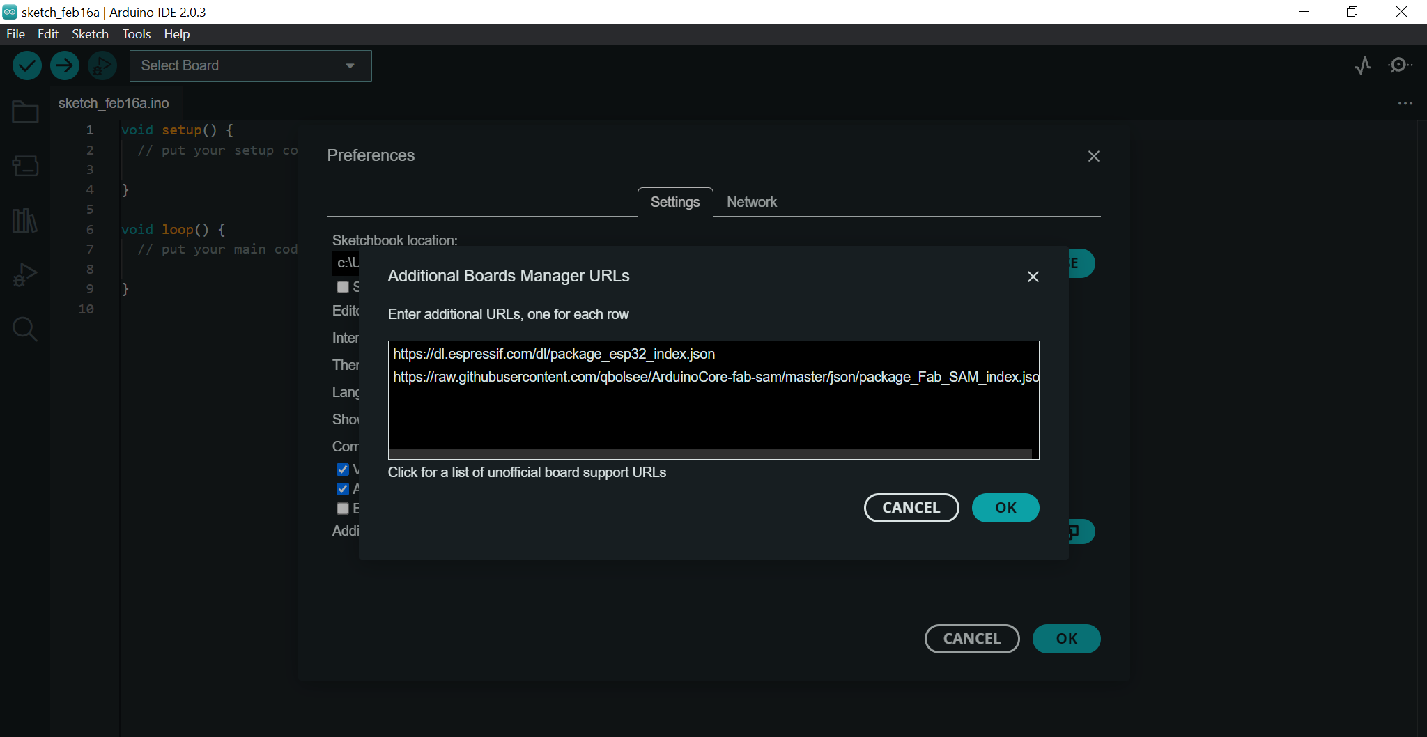
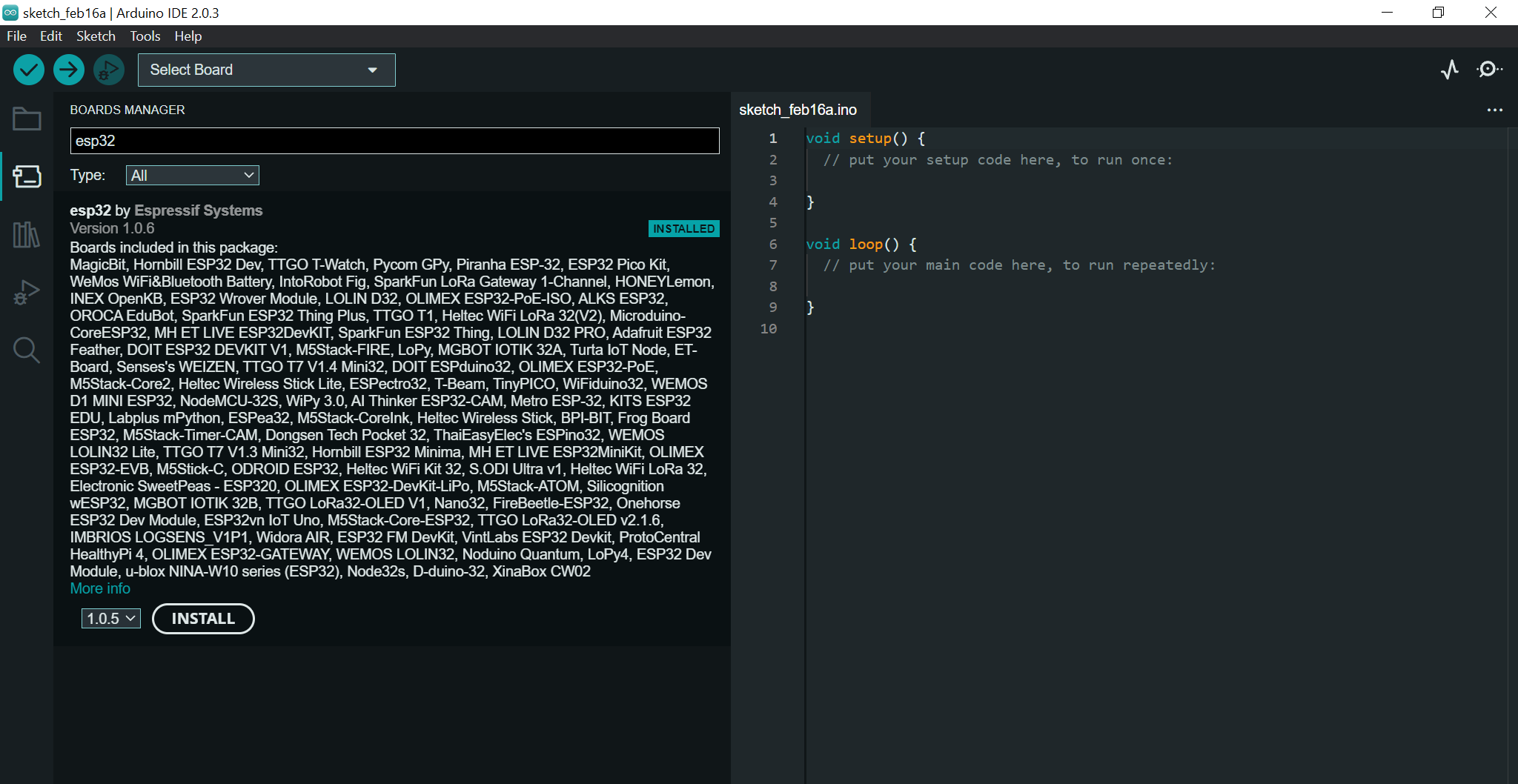
As far as the software side of things go, the preparation was very simple. I already had Arduino IDE downloaded and installed, I had to download the boards needed to communicate with the ESP32 and SAMD11. I copied then pasted the following links in Arduino's Additional Board Manager URLs under preferences so the IDE can find them online.
https://dl.espressif.com/dl/package_esp32_index.json
https://raw.githubusercontent.com/qbolsee/ArduinoCore-fab-sam/master/json/package_Fab_SAM_index.json
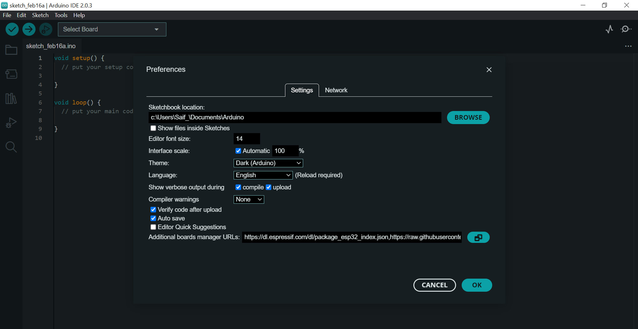
Of course, I had to fiddle around the settings in the preferences to make sure that I can hack into NASA comfortably.
Then I went to the Boards Manager menu searched for esp23 and Fab SAM to download the boards.
Finally, the software was setup and ready to use.
Hardware
Although I am not in Barcelona yet, I will talk about the process of setting up the board so as soon as I arrive, I'll be able to do it right away. As I have mentioned before, the board given to us was the Barduino 3.0 with an ESP32 microcontroller paired with an ATSAMD11C14A which will be used as a serial bridge. To my understanding, the ESP32 does not have the capability to perform serial communication, so the SAMD11 will do the honours, it will be the translator in a way.
The process started by uploading the bootloader to the SAMD11 since it was virgin, so I can program it and set it up as the serial bridge. First, I connected the SWD programmer to the Barduino 3.0 then connected both to the PC. The SWD programmer stands for Serial Wire Debug, and it is a protocol used to debug and program microcontrollers, they are commonly used to write firmware for microcontrollers. Afterwards, I opened the terminal and used the following command to upload the bootloader to the SAMD11.
edbg -ebpv -t samd11 -f free_dap_d11c_mini.bin
Then, I opened the Arduino IDE and have found the board in the ports list. Step one complete!
For the next step, since I have the ability to communicate with the SAMD11 through Arduino IDE, I used this code to program it as a serial bridge. With this I was able to establish the first contact with the ESP32. To do so, at the bottom of the board, there is a small switch in which I set it to the left. This means that the board will boot in flash mode ready to receive the code, but I had to press the reset button on the top right before uploading the code. Once the code was uploaded, I flicked the switch to the right then pressed the reset button, then the ESP32 was performing smoothly.
Personally, one of the things that made me prefer Arduino over Barduino 3.0 was the process of uploading the code to the board. Arduino does the booting in flash mode then resetting itself automatically, whereas in the Barduino 3.0, I have to do the above process every time I upload any code, and this means even if I want to reupload a code that had a typo or a wrong pin number by accident.
For this section, I had the Arduino on hand, so I started to learn and experiment with it. The tough part was to remember all the commands and the functions, however, the references page in Arduino's website helped me a lot.
Anyways, I already had the Arduino kit too, and what is better to do than going through the provided tutorial projects? Literally everything else! Nevertheless, I went through the first seven tutorials which are available in this PDF, and they helped me a lot.
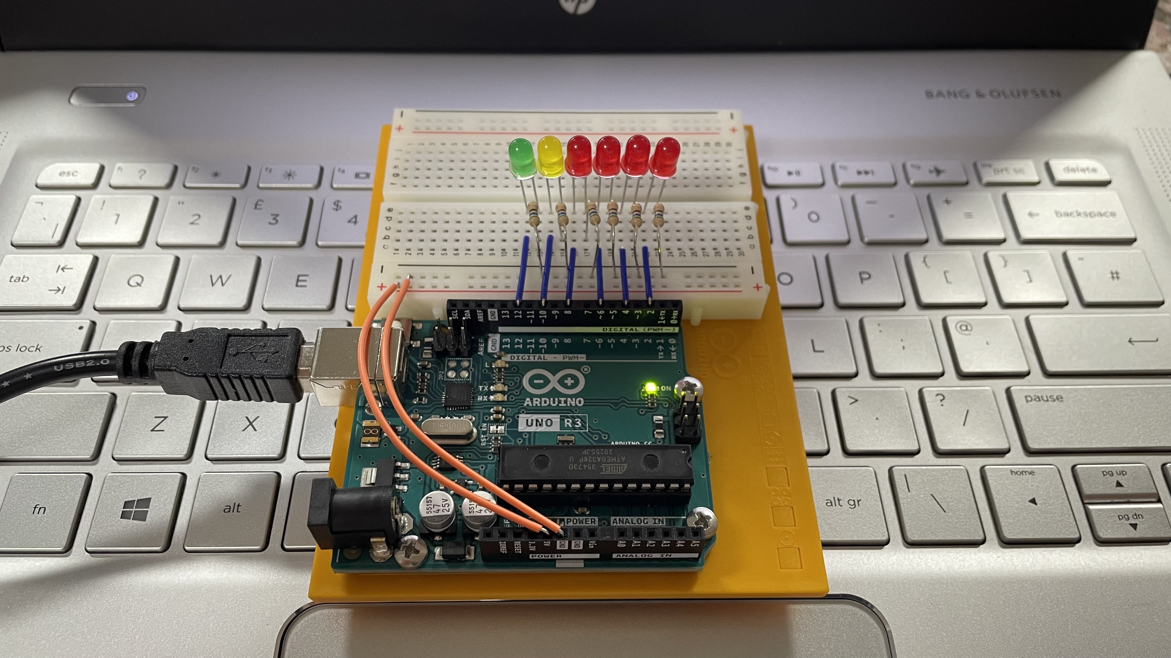
The task for this assignment was to program a microcontroller development board to interact and communicate, and that's exactly what I did. Imagine doing otherwise… heh! I did something I think its cool, Morse Code through LEDs. Here you can find the code.
void setup() {
// Set digital pins 2, 4, 6, 8, 10, and 12 as output pins
pinMode(2, OUTPUT);
pinMode(4, OUTPUT);
pinMode(6, OUTPUT);
pinMode(8, OUTPUT);
pinMode(10, OUTPUT);
pinMode(12, OUTPUT);
// Initialize serial communication with the computer at a baud rate of 9600 bits per second
Serial.begin(9600);
}
void loop() {
// Check if there is any data available to read from the serial port
if (Serial.available() > 0) {
// Read the first character of the data received from the serial port
char incomingByte = Serial.read();
// If the incoming byte is a dot '.', blink the LED connected to pin 6
if (incomingByte == '.') {
digitalWrite(6, HIGH); // Turn on the LED connected to pin 6
delay(100); // Wait for 100 milliseconds
digitalWrite(6, LOW); // Turn off the LED connected to pin 6
delay(100); // Wait for another 100 milliseconds
}
// If the incoming byte is a dash '-', blink the LEDs connected to pins 2, 4, 6, and 8 in sequence
if (incomingByte == '-') {
digitalWrite(2, HIGH); // Turn on the LED connected to pin 2
digitalWrite(4, HIGH); // Turn on the LED connected to pin 4
digitalWrite(6, HIGH); // Turn on the LED connected to pin 6
digitalWrite(8, HIGH); // Turn on the LED connected to pin 8
delay(300); // Wait for 300 milliseconds
digitalWrite(2, LOW); // Turn off the LED connected to pin 2
digitalWrite(4, LOW); // Turn off the LED connected to pin 4
digitalWrite(6, LOW); // Turn off the LED connected to pin 6
digitalWrite(8, LOW); // Turn off the LED connected to pin 8
delay(100); // Wait for another 100 milliseconds
}
// If the incoming byte is a space ' ', blink the LED connected to pin 10
if (incomingByte == ' ') {
digitalWrite(10, HIGH); // Turn on the LED connected to pin 10
delay(300); // Wait for 300 milliseconds
digitalWrite(10, LOW); // Turn off the LED connected to pin 10
delay(100); // Wait for another 100 milliseconds
}
// If the incoming byte is a forward slash '/', blink the LED connected to pin 12
if (incomingByte == '/') {
digitalWrite(12, HIGH); // Turn on the LED connected to pin 12
delay(700); // Wait for 700 milliseconds
digitalWrite(12, LOW); // Turn off the LED connected to pin 12
delay(100); // Wait for another 100 milliseconds
}
}
}
As seen in the above code, I have added the main characters in a Morse Code:
- - Dot = “.”
- - Dash = “-“
- - Forward Slash = “/”
- - Space Bar = “ ”
The dots only turn on the middle red LED, the dashed turn on all four red LEDs, the space bar turns on the yellow LED, and the forward slash turns on the green LED. Letters are made from a combination of dots, dashes, and spaces to create words, and forward slashes are there to separate the words.
The duration of a dot is the basic unit of time: each dot or dash is separated by an off time equal to the duration of a dot; each dash is three times as long as a dot, and each letter is separated by an off time equal to three dots. Finally, each word is separated by an interval equal to seven dots. I got this paragraph from this website. I chose the unit of time to be 100 milliseconds in this example:
- - Dot (1 unit) = 100ms
- - Dash (3 units) = 300ms
- - Dot Dash Space (1 unit) = 100ms
- - Letter Space (3 units) = 300ms
- - Forward Slash (7 units) = 700ms
I used this Morse Code Translator website to translate the following sentences into Morse Code. There is a play button which makes you hear how it sounds too!
Welcome to FabLab Barcelona!
.-- . .-.. -.-. --- -- . / - --- / ..-. .- -... .-.. .- -... / -... .- .-. -.-. . .-.. --- -. .- -.-.--
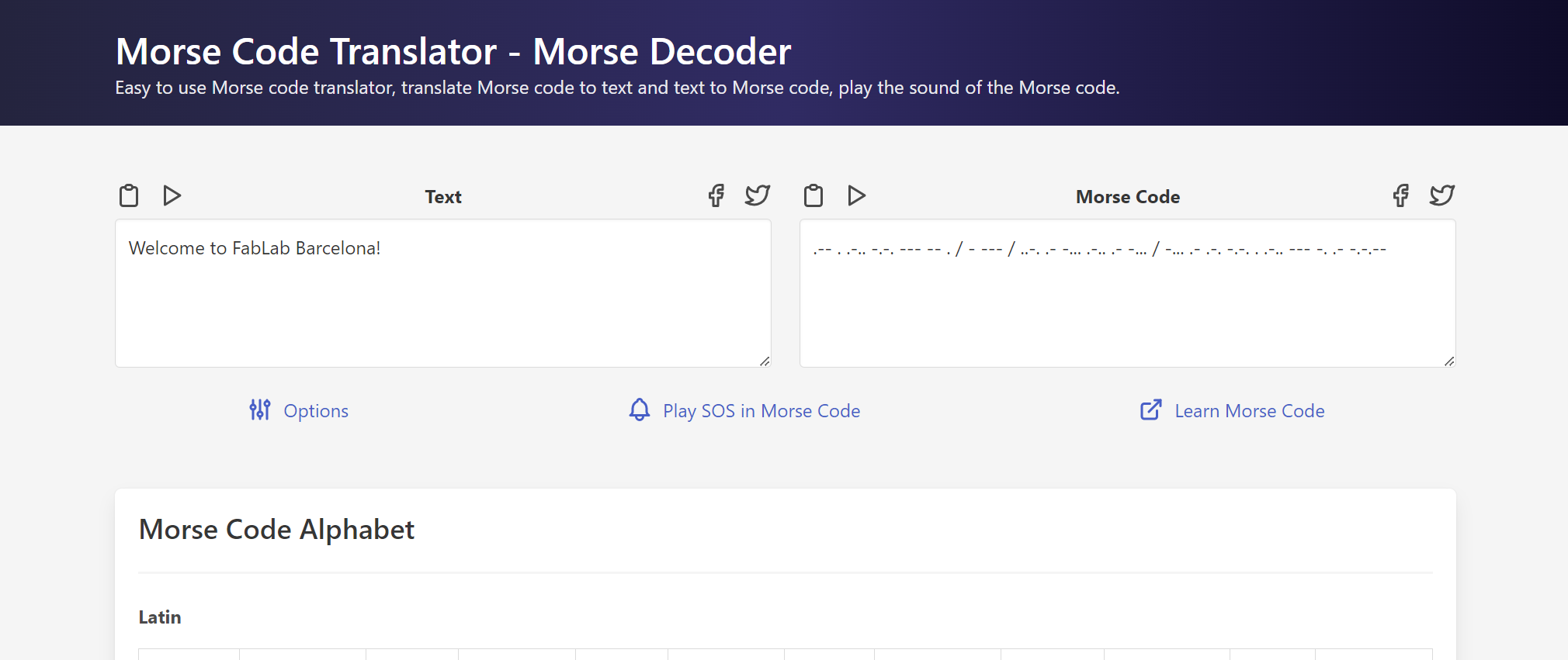
Then I copied and pasted the Morse Code into the Serial Monitor then pressed enter.
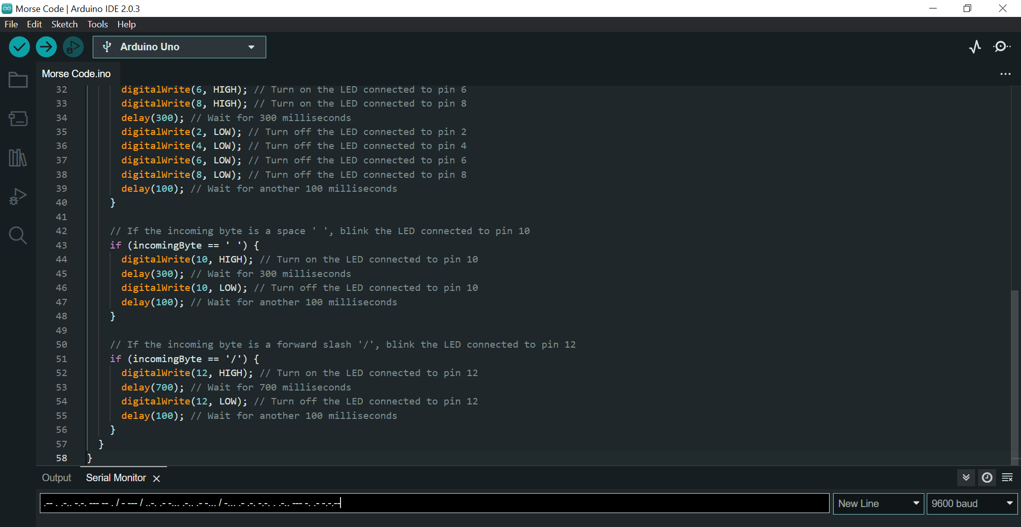
Here is a video of how the code looks.