
Week 03 - Computer Controlled Cutting
This week was about learning how to use a laser cutting and a vinyl cutting machines. I have never used a vinyl cutting machine before but used a laser cutting machine. However, for the laser cutting machine, everything was set up and ready to use so I never dove into the logic and the parameters of such machines. In addition, I used the machine for an acrylic piece that I was using as a logo, so there was no tolerances/kerf to be considered, nothing, just a simple piece with a time-lapse video at my disposal to brag about. The great thing about laser cutting machines is that with the proper design in mind, these machines can be used to create a quick and a cheap prototype to test whatever design I am testing. A quick side note, did you notice how many times I said the word machine?
Group Assignment
For this assignment, the first step is that it required students to be present at the lab, and I am not, how about that? Well, my visa did not come out yet, so I am doing the course online up until the visa arrives. Anyways, I was not able to learn how to use the machines but thanks to Fab Academy Barcelona for providing tutorial videos, they were of great help.
Well, I was at least able to help by creating the website using a template from HTML5 UP, and hopefully to use this website for the coming weeks too. The group managed to learn how to use the laser cutting machine 'Trotec Speedy 400' and have created some test samples to check for the kerf of the cutter. There where three samples with three different materials to test, wood, acrylic, and cardboard. Of course, each material has its own kerf due to how the laser reacts to the material itself while cutting.
They created samples of each material in which the design was some sort of a tolerance gauge, and the design is somewhat smart. It looks like a comb and the distance between two adjacent teeth is the same as the material thickness, however, the kerf value is subtracted from it, and its value increases in size as you go through the teeth of the gauge. Here is a simple example, let's say the material thickness is 3mm, so the distance between the first 2 adjacent teeth is 3mm minus a kerf value of let's say 0.05mm. Then the next adjacent set get a kerf of 0.1mm, the next will get 0.15mm and so on. With the resolution of 0.05mm, the accuracy should be more than enough to the applications that we will be doing.
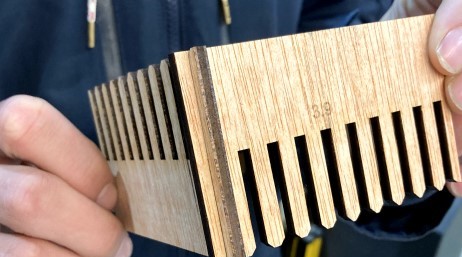
How tightly or loosely two components are when assembled depends on the kerf value, and the team chose the following values for the following materials to get a good grip when assembling the components:
- Wood: 0.20mm
- Acrylic: 0.05mm
- Cardboard: 0.20mm
Thanks to the team, I will be able to use the above values for my individual assignment.
Individual Assignment
Due to my circumstance, the plan for this assignment was to at least create the designs for the laser cutting and vinyl cutting machines and get them ready, so I'll be able to manufacture them as soon as I arrive.
Laser Cutting Machine
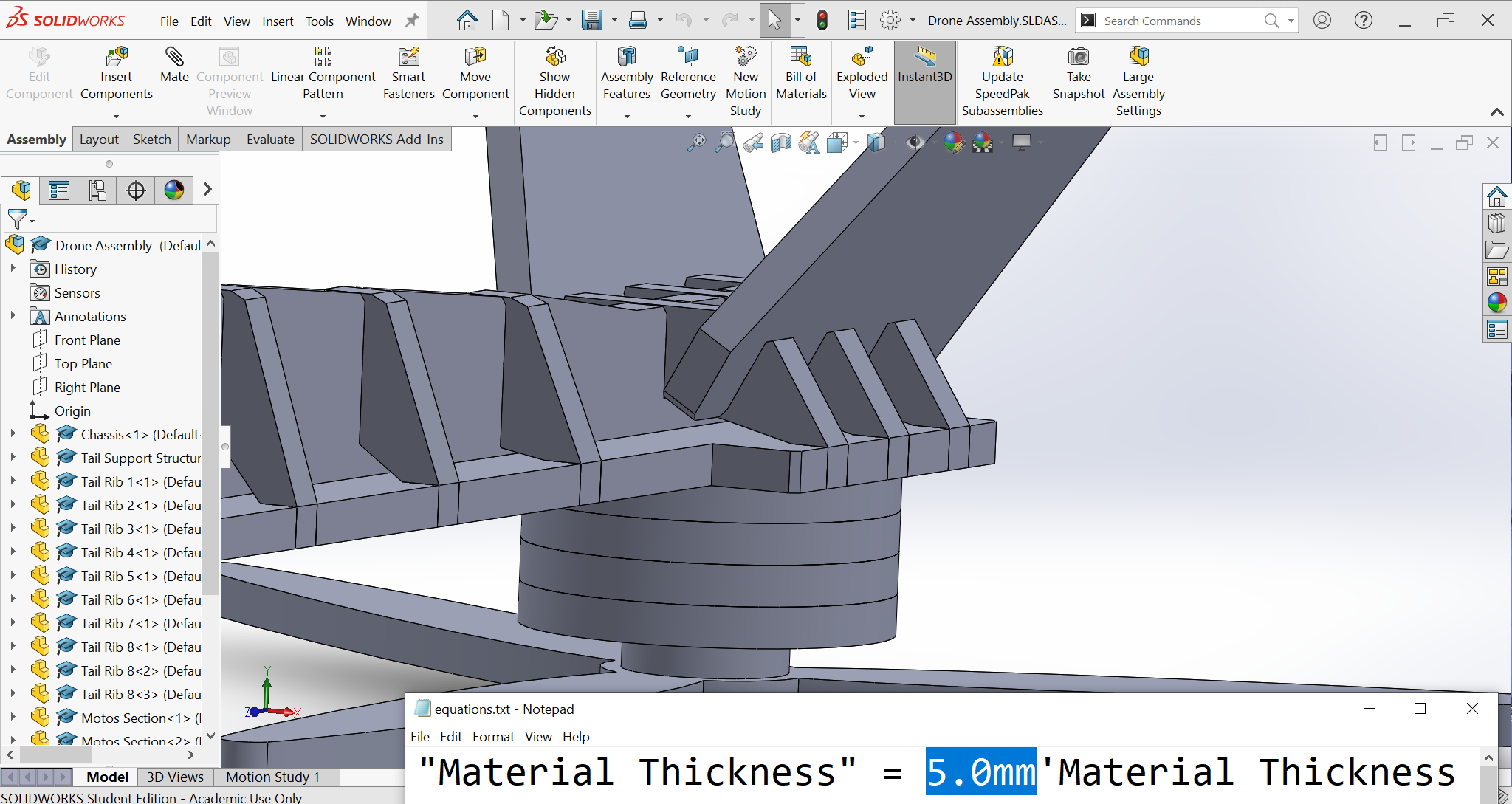
So, first things first, I created a parametric CAD file in SolidWorks, the parameters are called 'Global Variables', and what they do is after I link the measurements to them, I can control all linked measurements through these variables, basically they make life a little easier. The following image shows the window for the global variables.
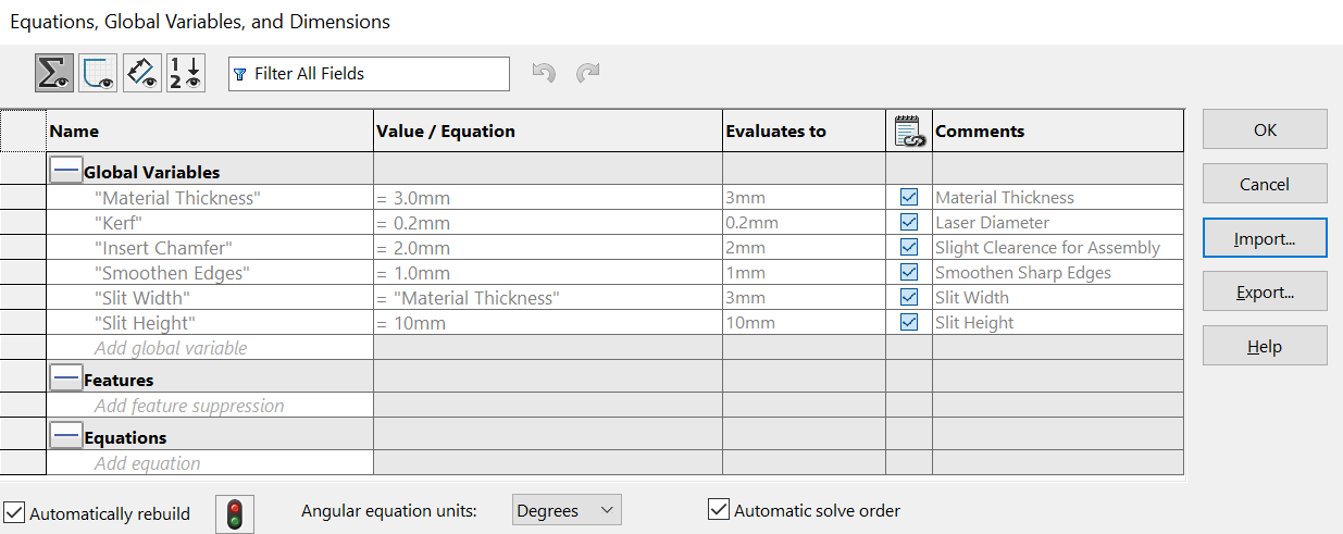
As seen above, I created some basic variables in which I can link the model with. However, I created an assembly file which has multiple components. In that case, to make all the components of the model parametric, I have exported the above table to a text file as seen below, then anytime I open a new SolidWorks file for a new component, I link that file to the text file.
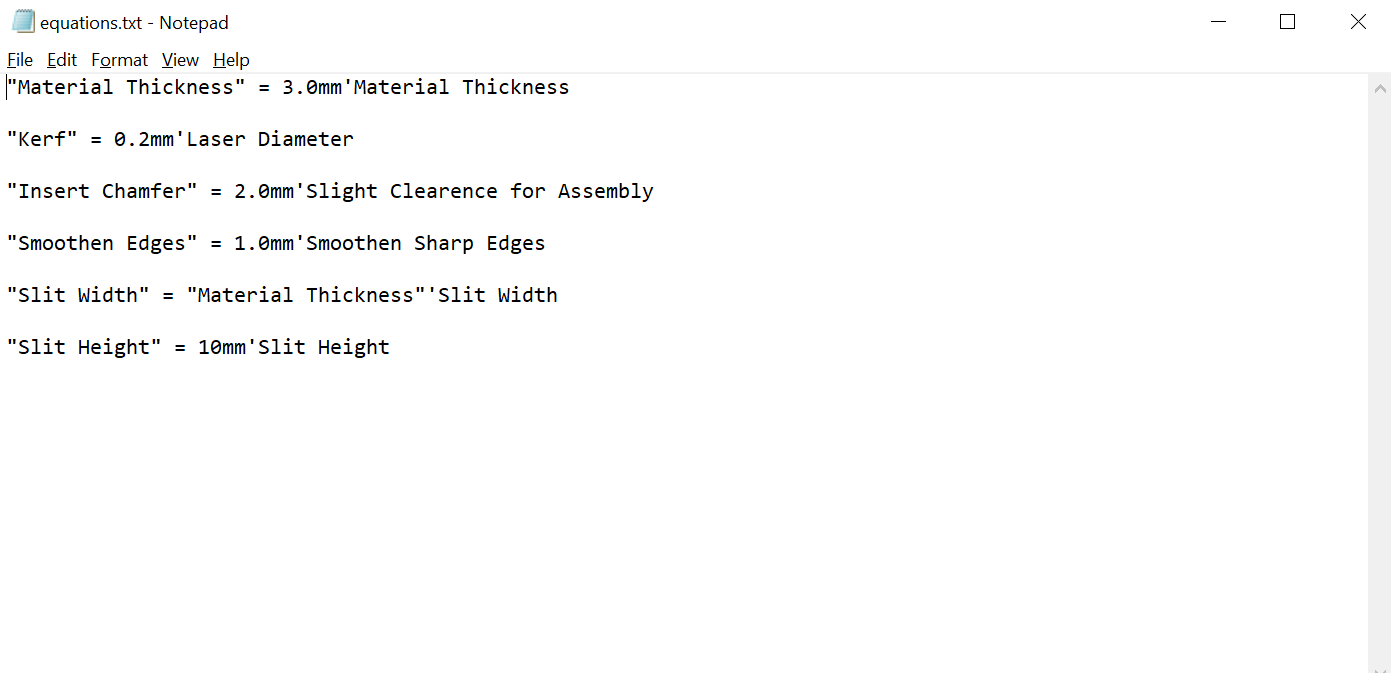
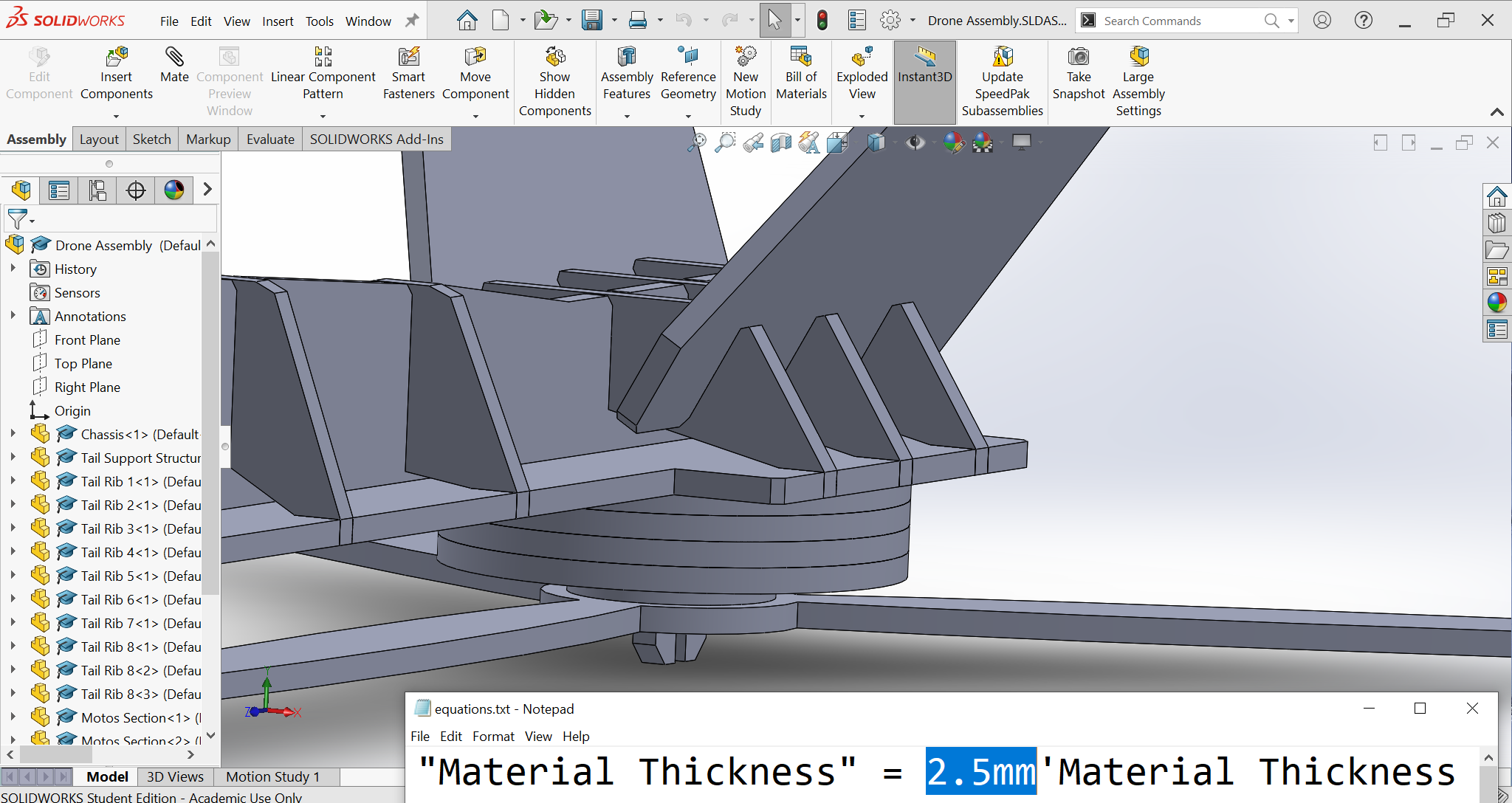
The great thing about having this text file is that the whole assembly is linked to it. So, by changing only one value, all the components in the assembly update. The following two images are an example, the first image has a material thickness of 2.5mm and the second image has a material thickness of 5.0mm. And just by updating the value on the text file, all the components have updated.
At this point, the wooden drone is fully designed and assembled while being fully parametric, a cool render is shown below.
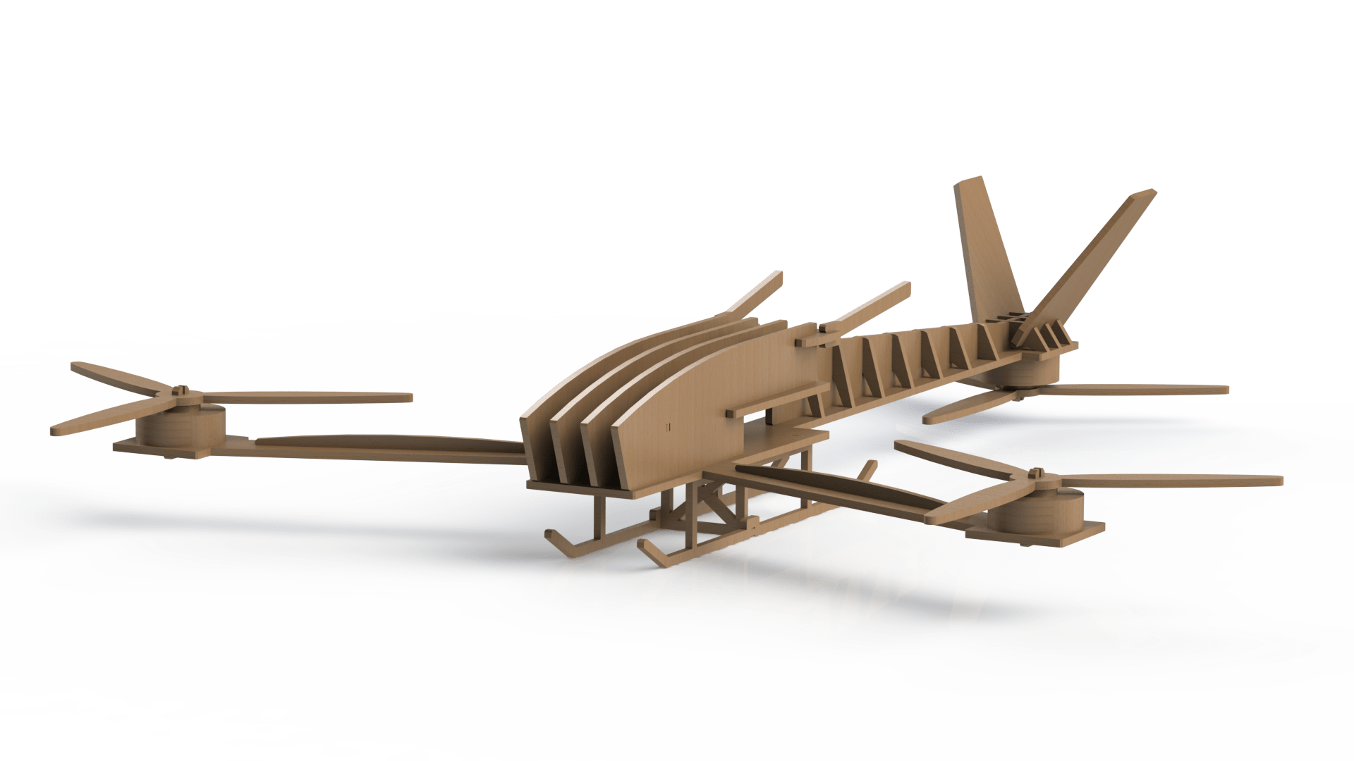
I can only do so much in the sense of manufacturing the wooden drone, I won't prepare an SVG file for laser cutting in case I decided to use a different material with a different thickness and kerf at my arrival. Although the model was optimized to be laser cut from wood with a thickness of 3.9mm and a kerf of 0.2mm, I would rather wait until I arrive to the lab to create the file for the machine.
Speaking about creating a file for laser cutting, I decided to use Deepnest since this software is free and easy to use. I have downloaded the software and watched a quick tutorial on how to get started. Some of Deepnest's advantages are:
- Very simple user interface
- Literally needs a 2min tutorial (I know that the above tutorial was about 11min)
- Can read and write DXF and SVG
COMING SOON!
Vinyl Cutting Machine
COMING SOON!