The task list for this week:
- Model (draw, render, animate, simulate, ...) a possible final project.
- post it on your class page with original 2D and 3D files.
2D Designe
This week I focus on exploring various 2D & 3D design software. Let's see the first 2D design
Raster Vs Vector:
2D image designs are classified into two major categories
- Raster.
- Vector.
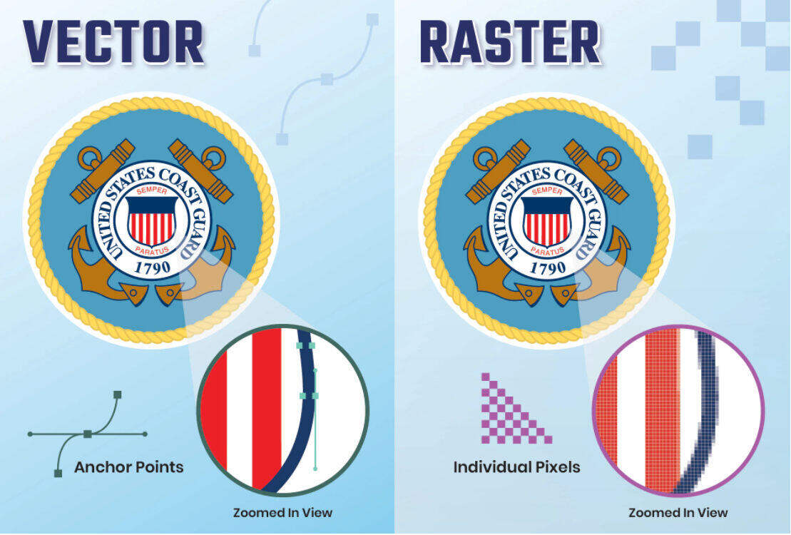
Raster: Raster img are made of pixels or tiny dots that use color and tone to produce the image.
Vector: Vector graphics are digital art that is rendered by a computer using a mathematical formula.
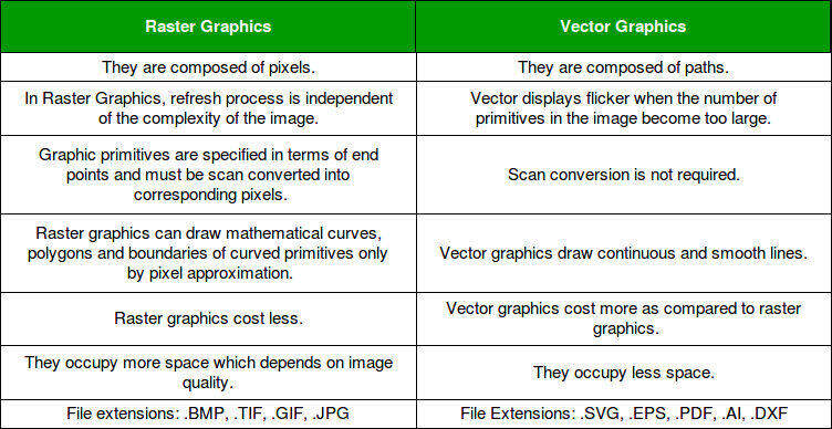
In the following table, I covered the difference between vector and raster to know more about it check this blog.
As an engineer, I have a little bit of a good hand on CAD software but I have not explored 2D modeling up till now . Software like gimp, photoshop are known to me but I am going to explore them for the 1st time in my life. 2D designing.
Inkscape:
To start with the 2D design I started learning Inkscape. As it's open source and most of the content is available online.
Here is how I started learning it.
Downloading and installing Inkscape.
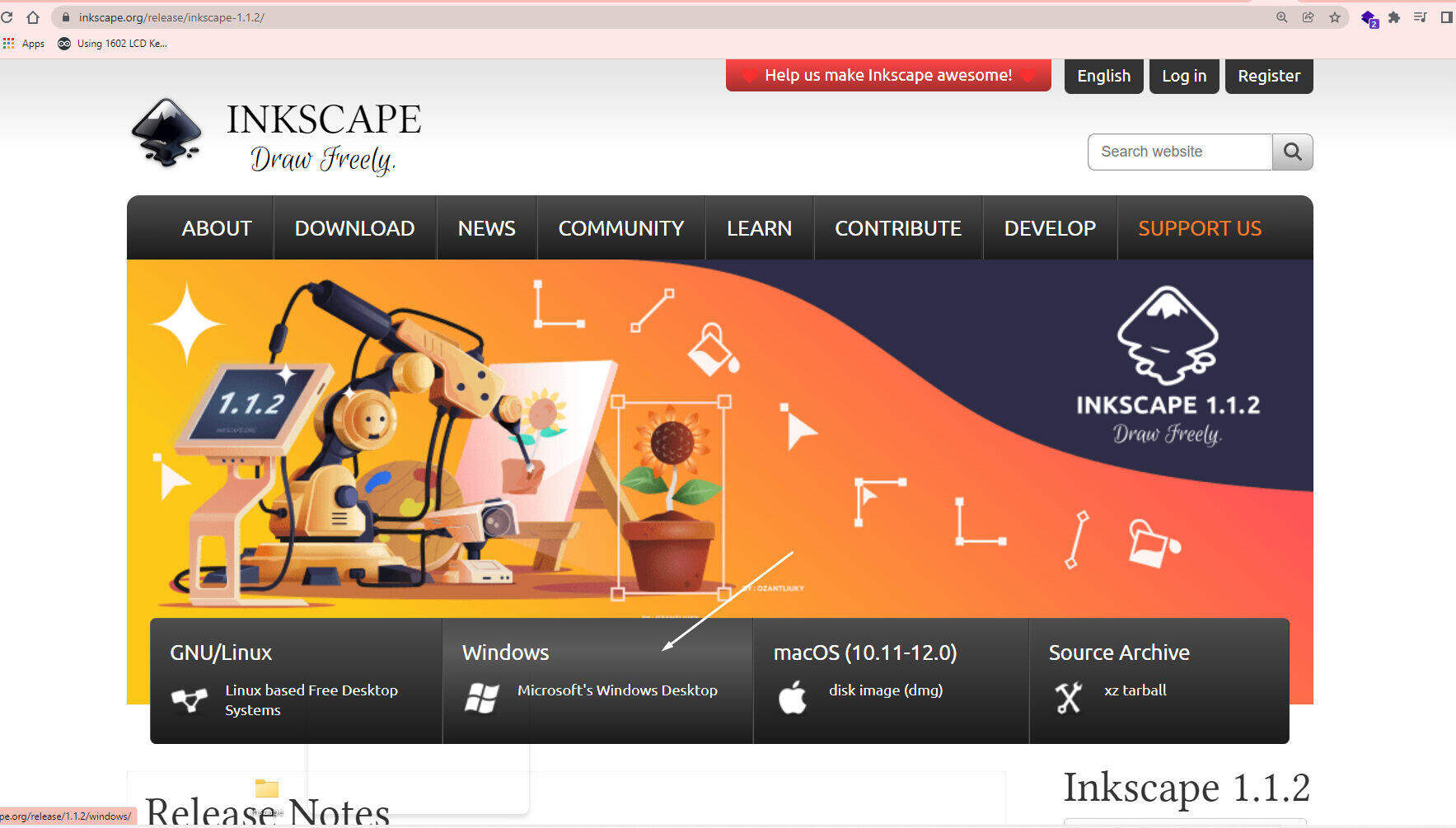
It’s very simple to download and install Inkscape. You just have to go to Inkscape.org And select the version based on your OS. As I use Windows, I select the Windows version of Inkscape and download it into my system. I got a .exe file. For installation I just opened it.
Step 2. Exploring the user interface and layout.
Usually, whenever I start exploring any new software for the 1st time I use to read the manual of the software which provides basic information about it.
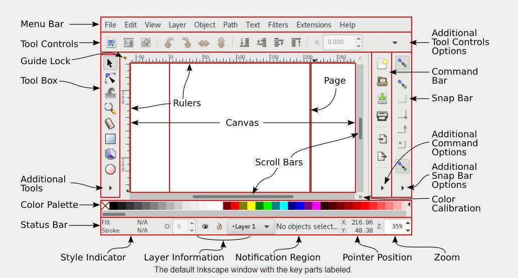
This is the basic interface of Inkscape I got from their user manual.
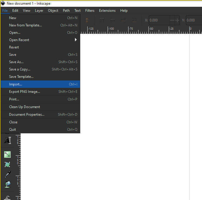
Step 3. :Now its time to make some thing using inkscape.So i decide to try one of tool for tracing a bitmap image into a path .for that I fallow this tutorial from Inkscape manule you can find such side tutorials on there side .
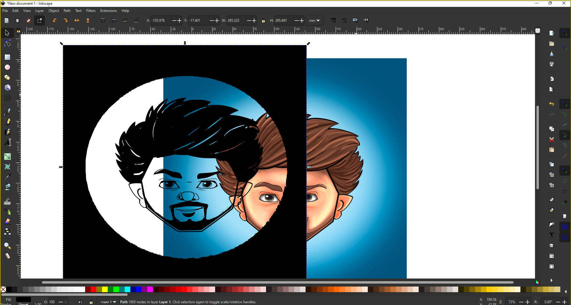
Step4:Opening the application and Import a Image for tracing a bitmap image into a path. I use the same illustration image of me for this activity.
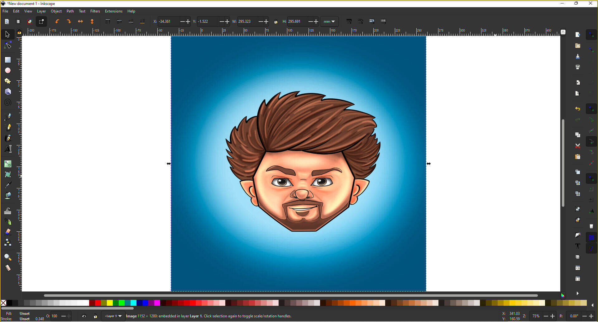
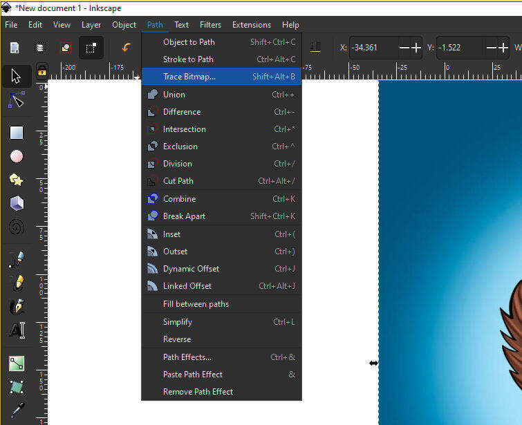
Step5:Then I select the path from the menu bar in path select trace bitmap option .update it for selected Image.
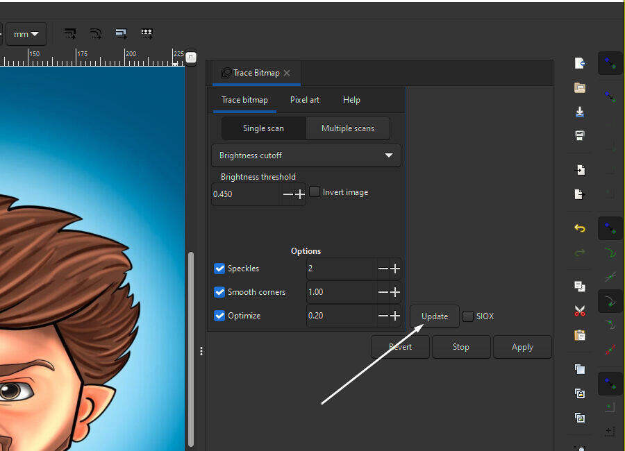
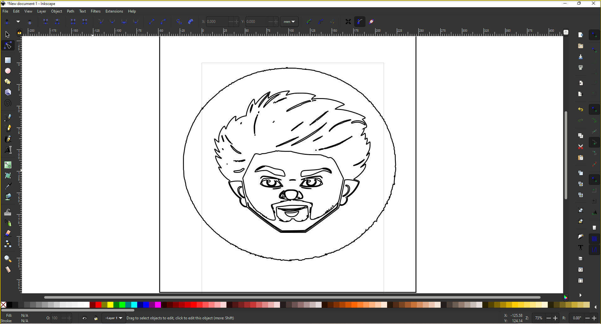
Step6:Its show the preview of the trace bitmap generated .Then apply the operation for the selected image by clicking on apply option.It will automatically generate a teace bitmap.
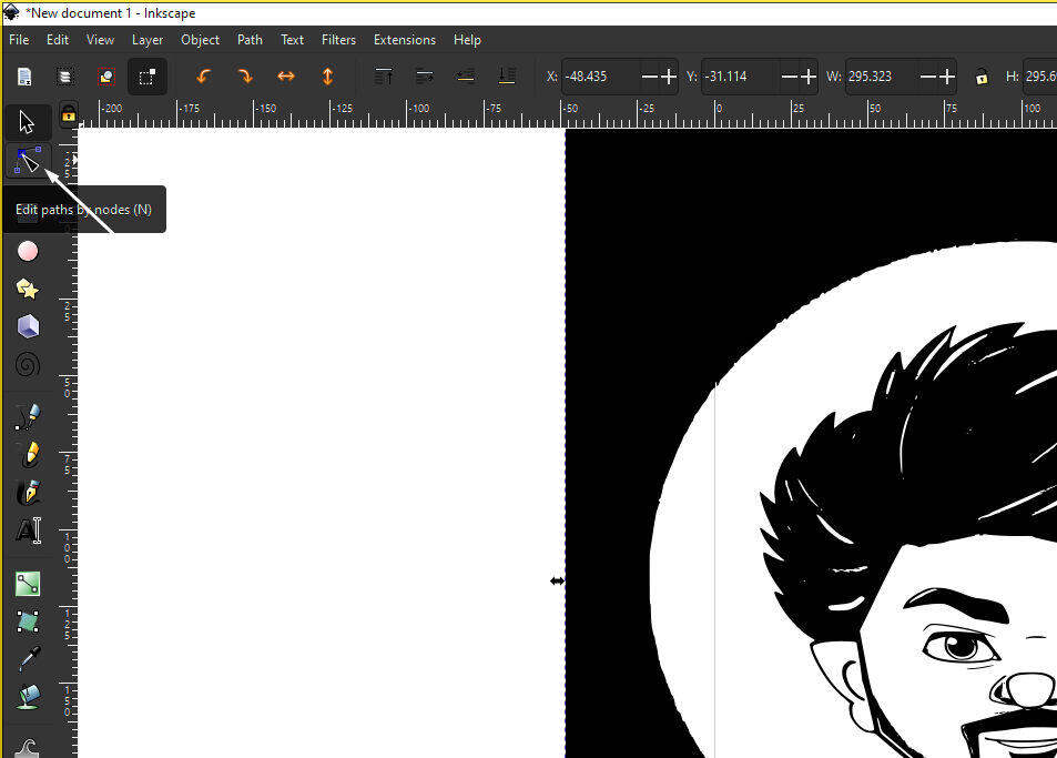
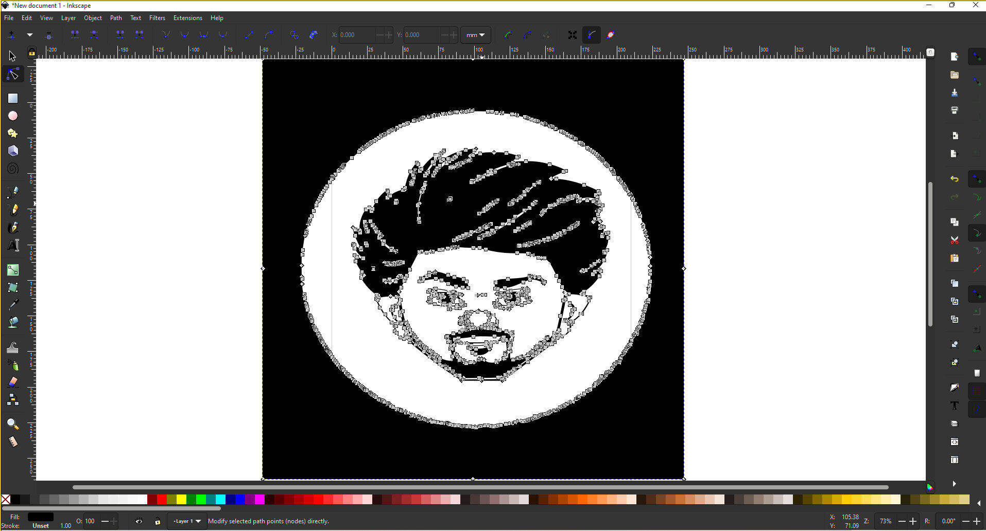
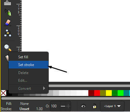
Step7:Then I fine adjusted the design using path tool editor and I used setstroke to map the boundry of design.
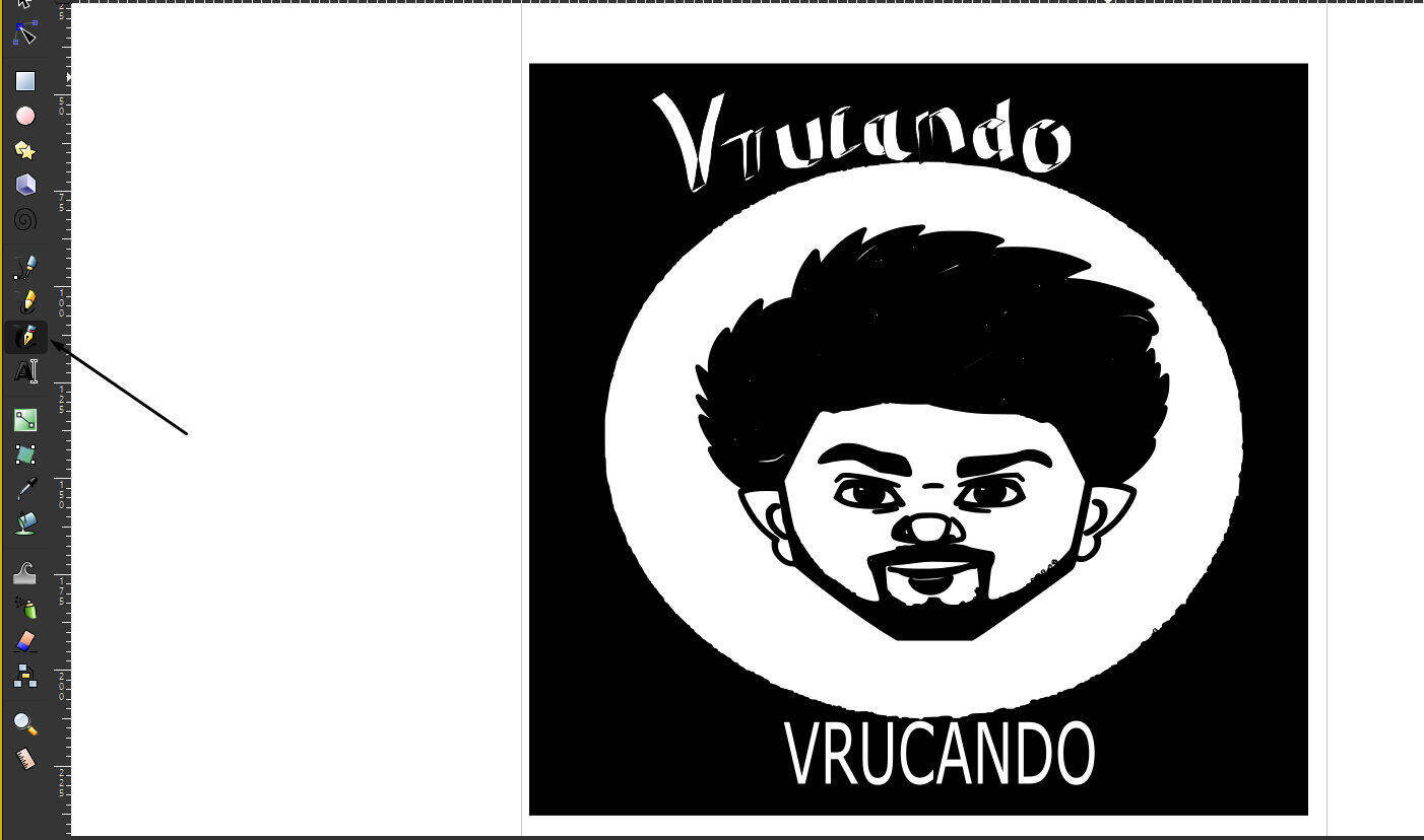
Step8:After maping the boundry of image I use Creat and edit text object tool to wright name below the edited path.
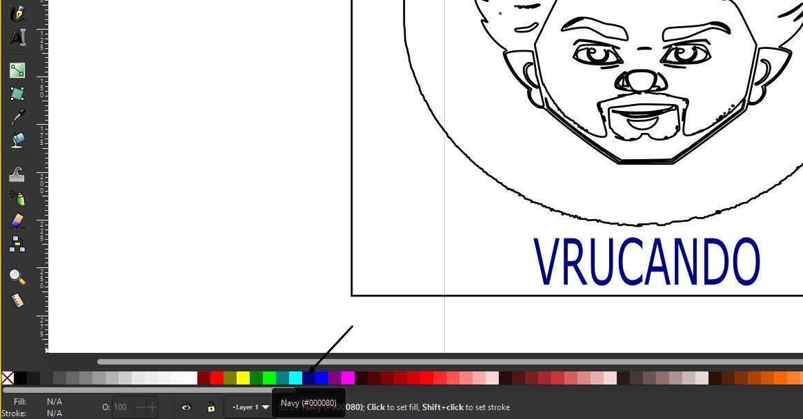
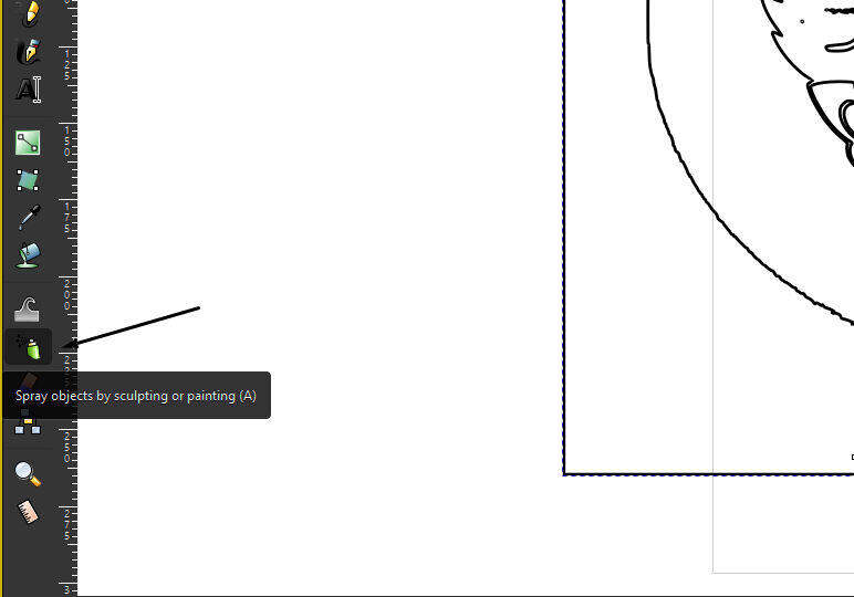
Step9:After this I added a boundry box to the design using the box option and coloured it like shown in the image using spray option .
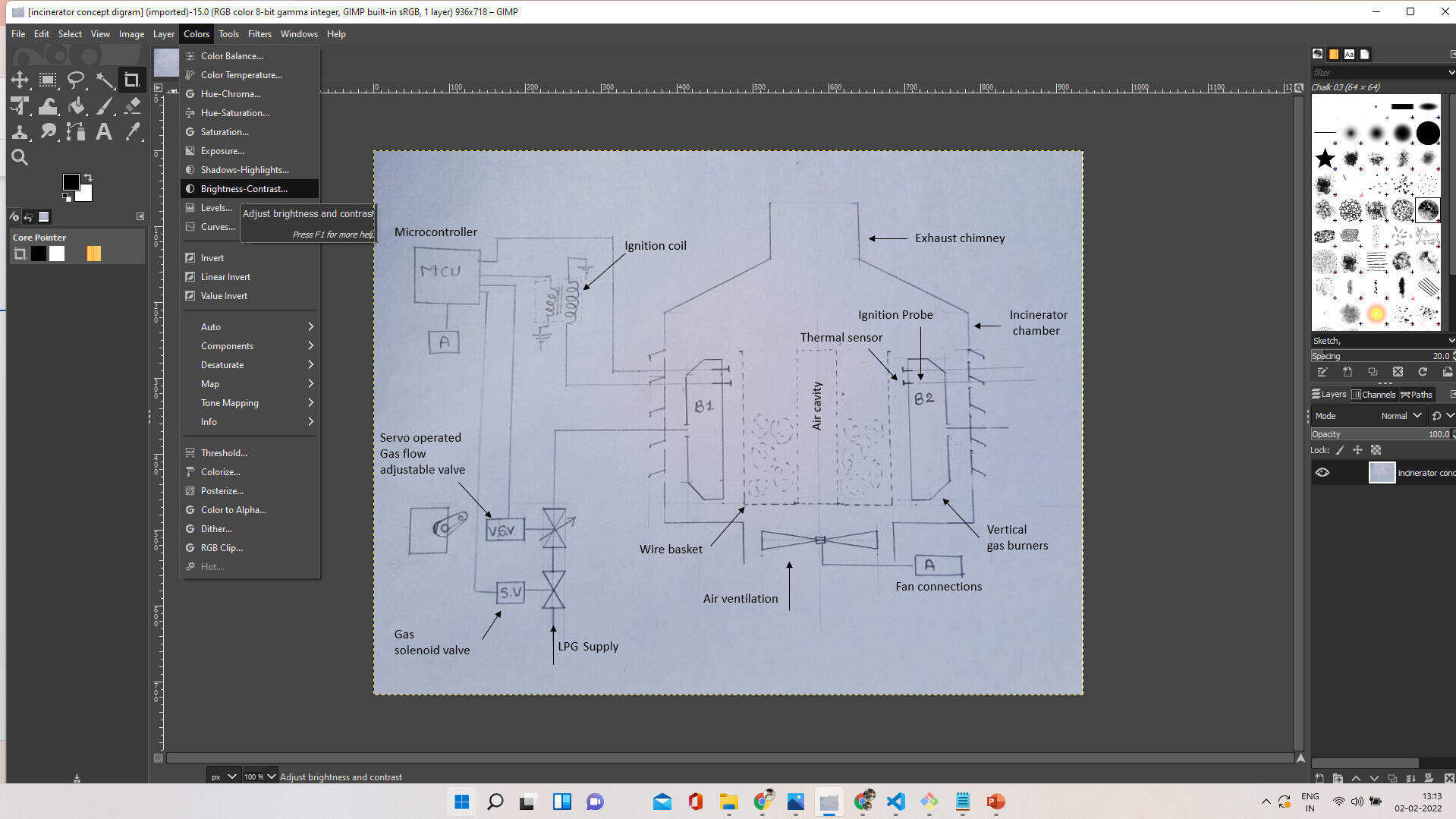
GIMP:
I use gimp for dearkening the fent lines on my sketch using brightness controller tool.
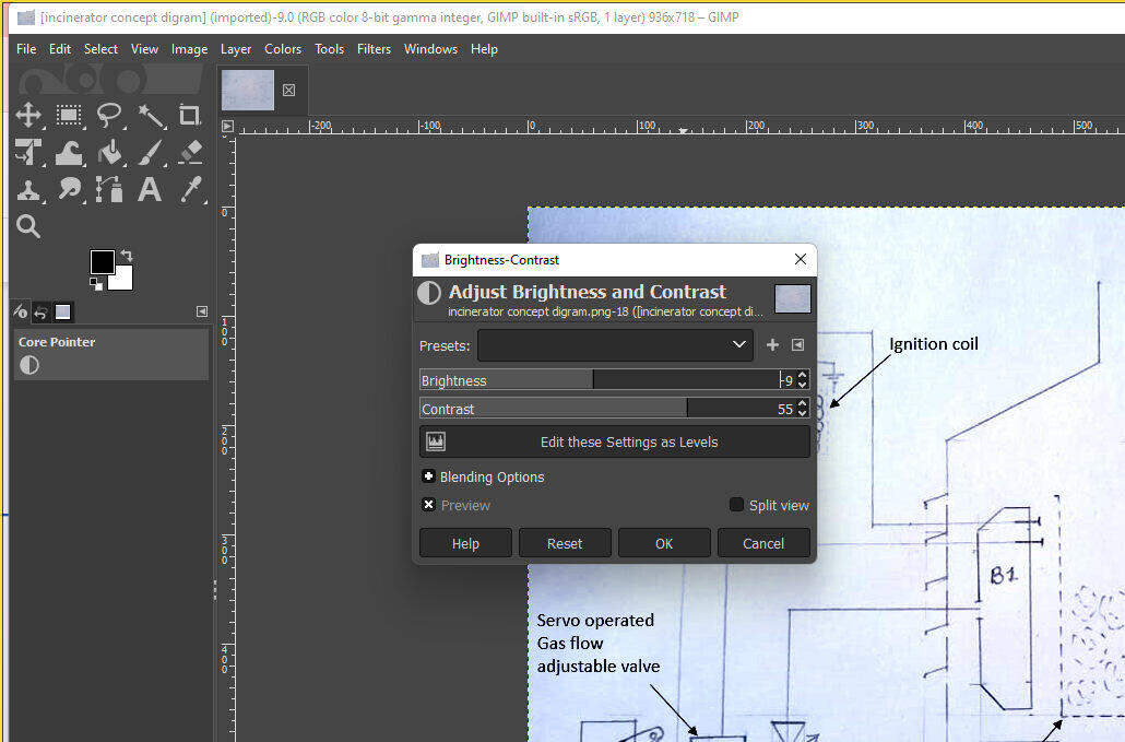
I also tyr Bim plugin in Gimp for compressing img.
3D Designe:
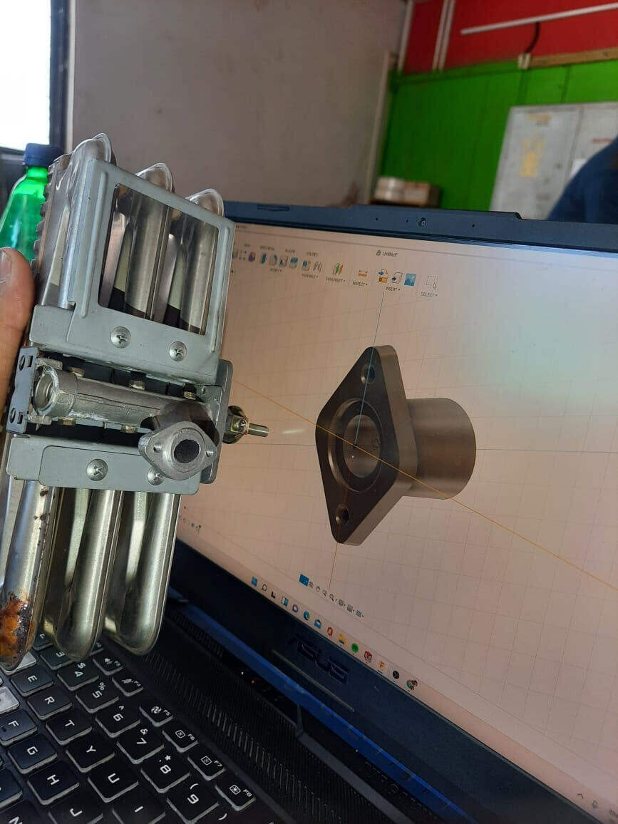
Fusion 360:
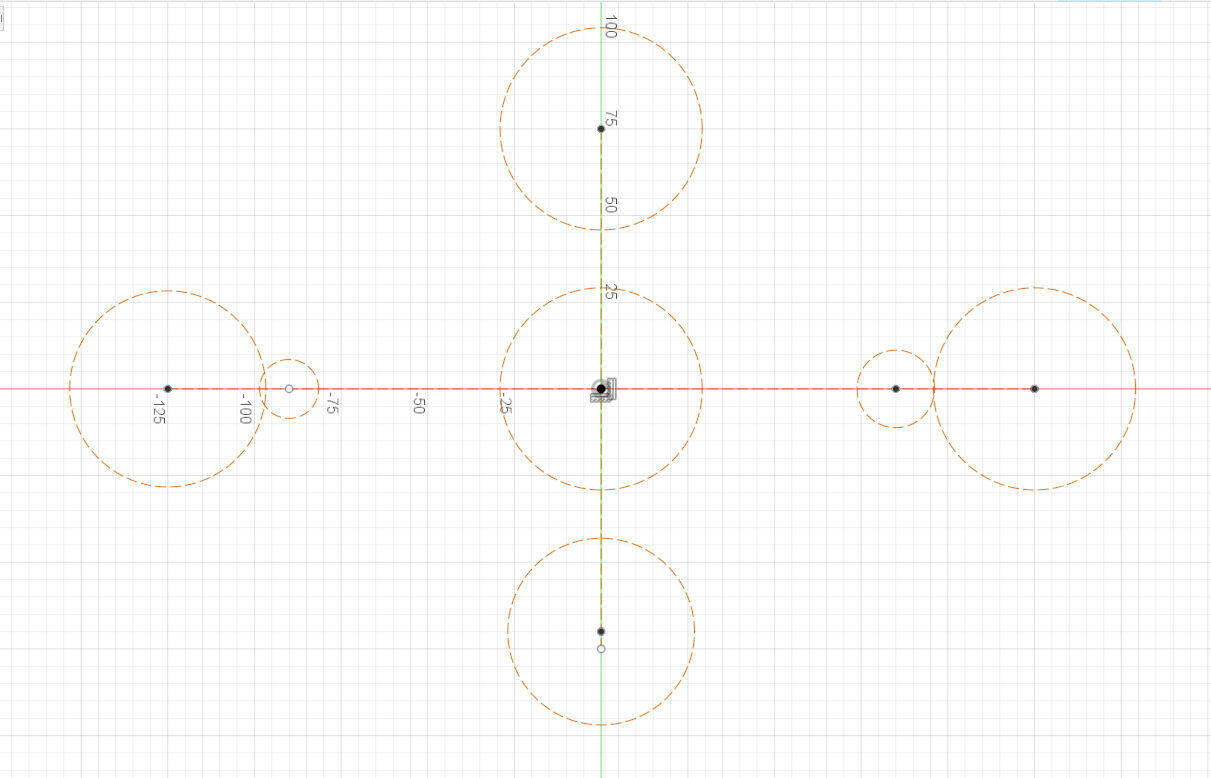
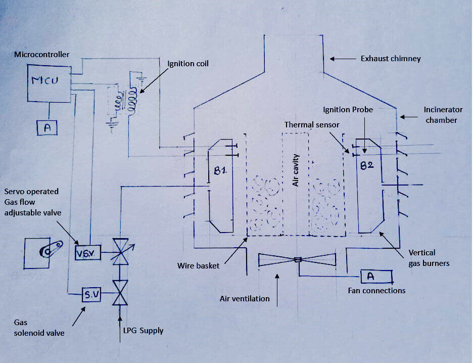
I need a connection element design for my burner So i tried to design one in Fusion 360.
1.Start with sketch mode Drawing some circles:
.
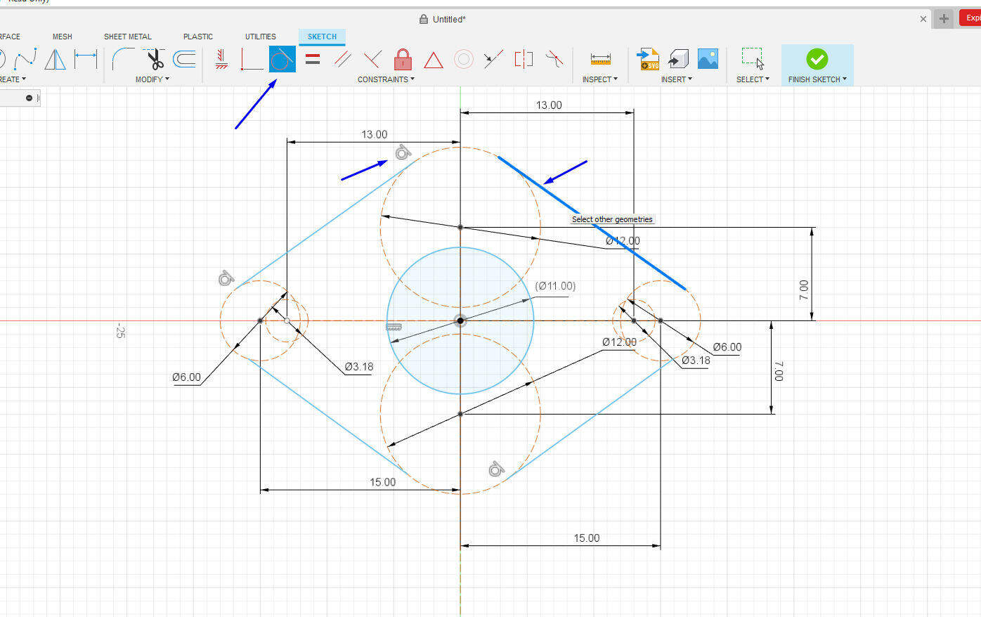
2.Defining dimensions for circles and there distance from each other :

.
3. Using tangent constraint:
.
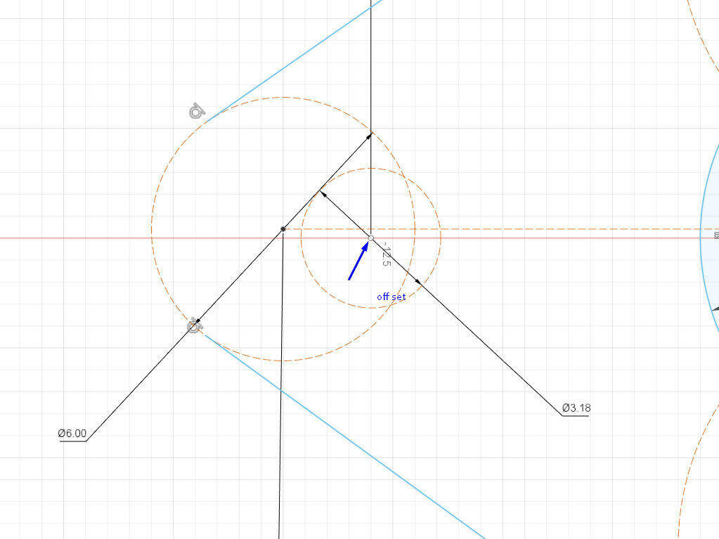
4.Detected Off set which can be a problem for Design.
.
5.Use Concentric constraint for making circle center allina.
.
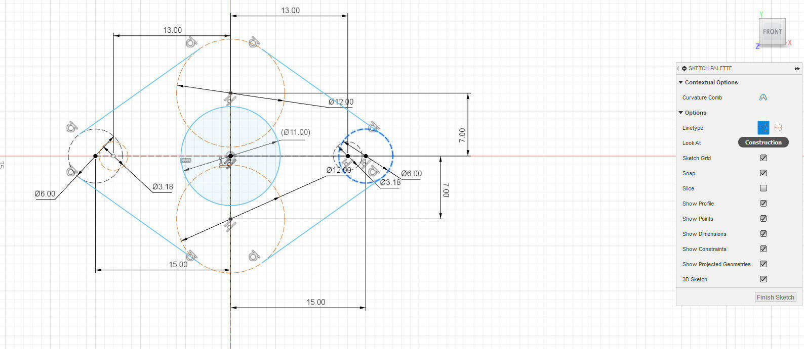
6.Convert construction line to object line :
.
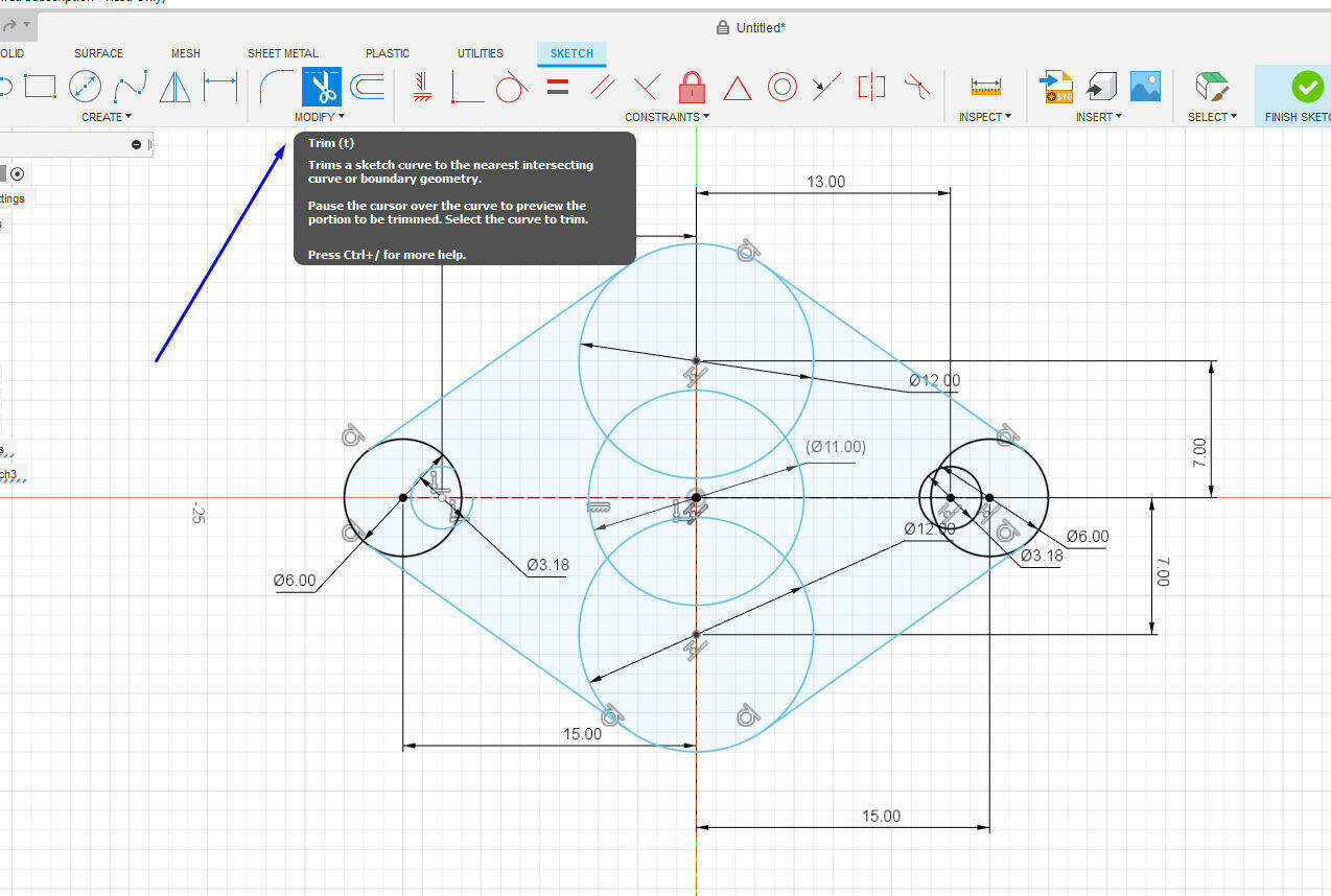
7.Use Trim tool to remove excess lines and curves in design:
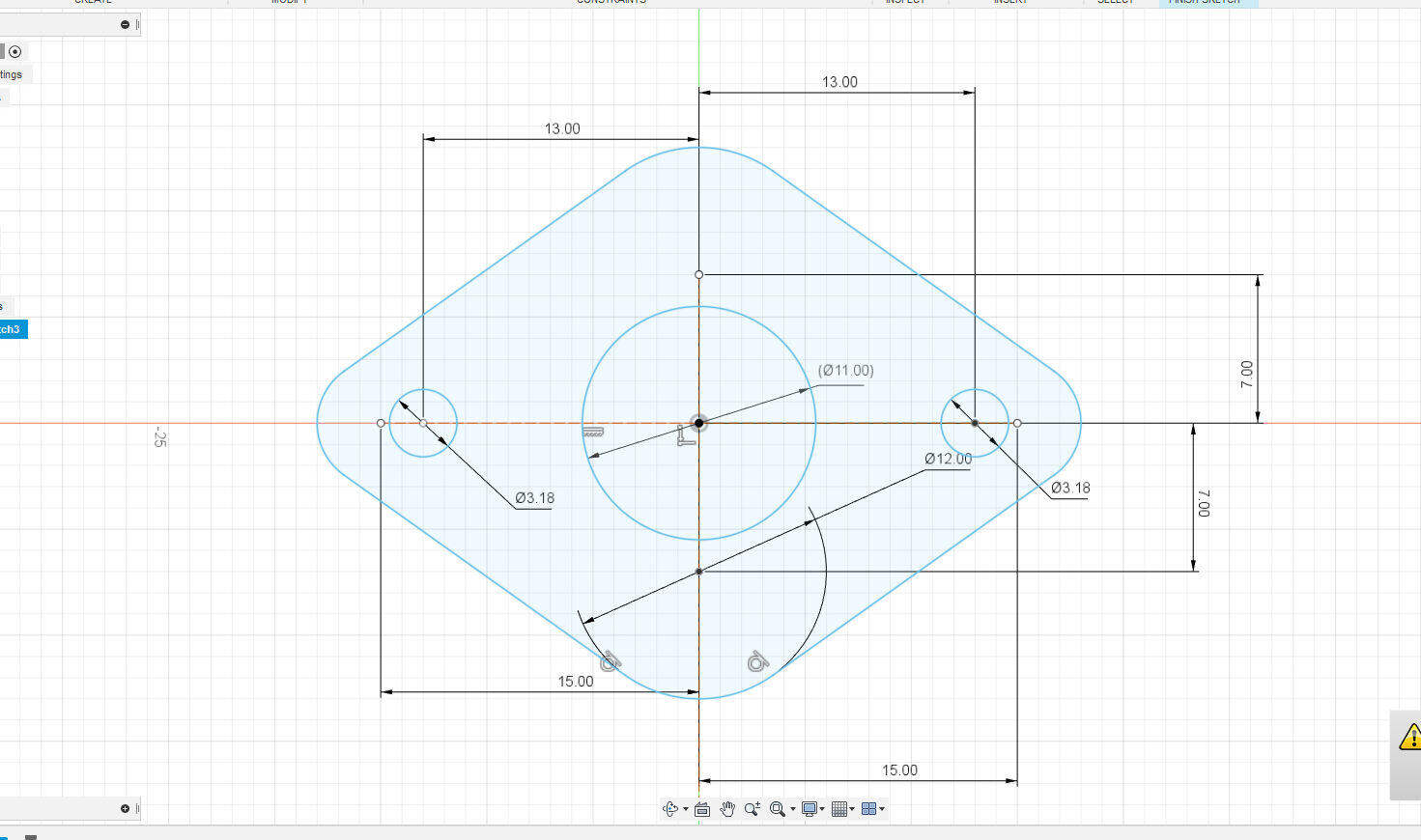
.
8.Use Extruded tool to generate body:

.
9.Select body surface and sketch circle on it:
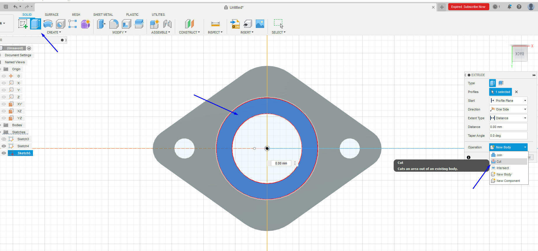
.
10.Cut the body using Extruded tool:
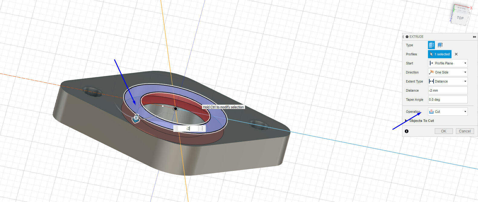
.
11.Use Chamfer tool for creating chamfer:
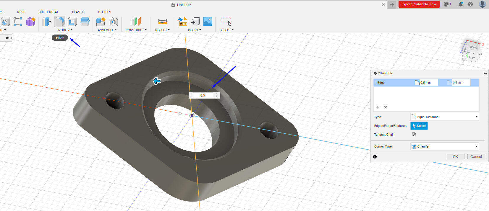
.
12.generating body on body by extrugion.
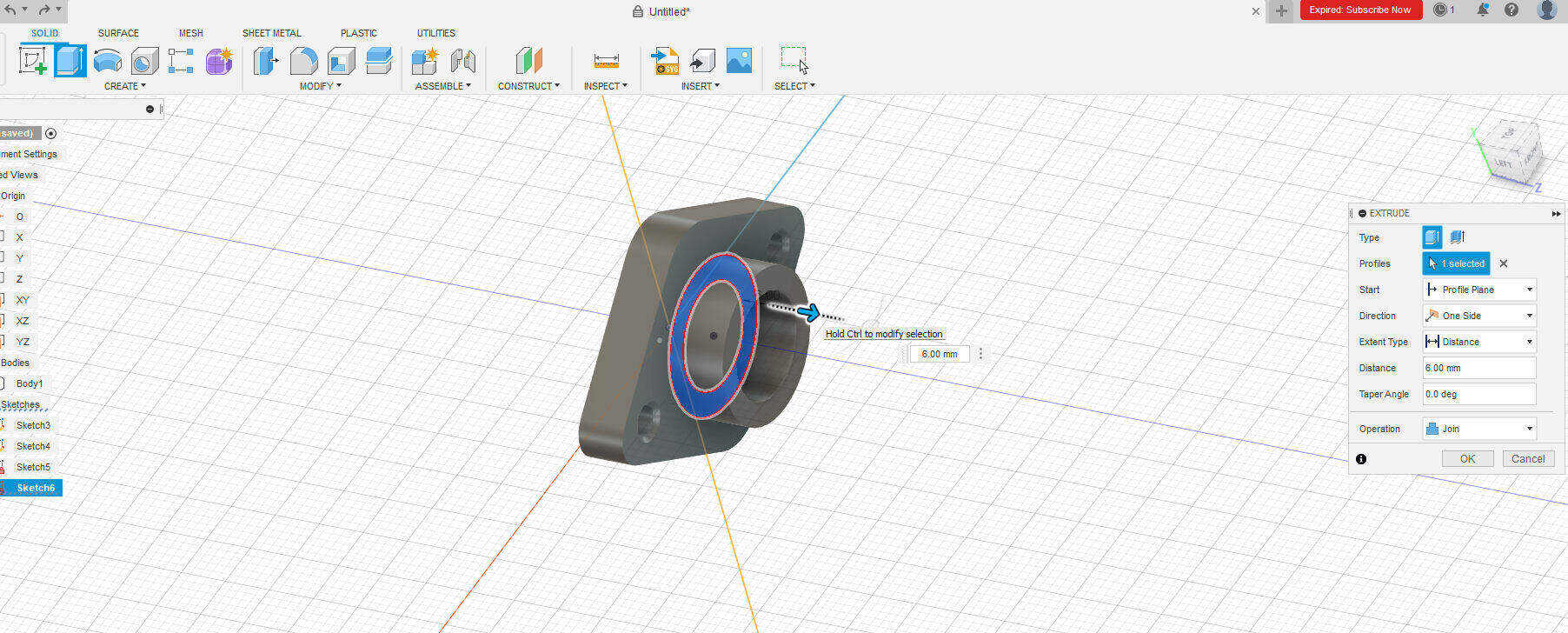
.
13.Final Design:
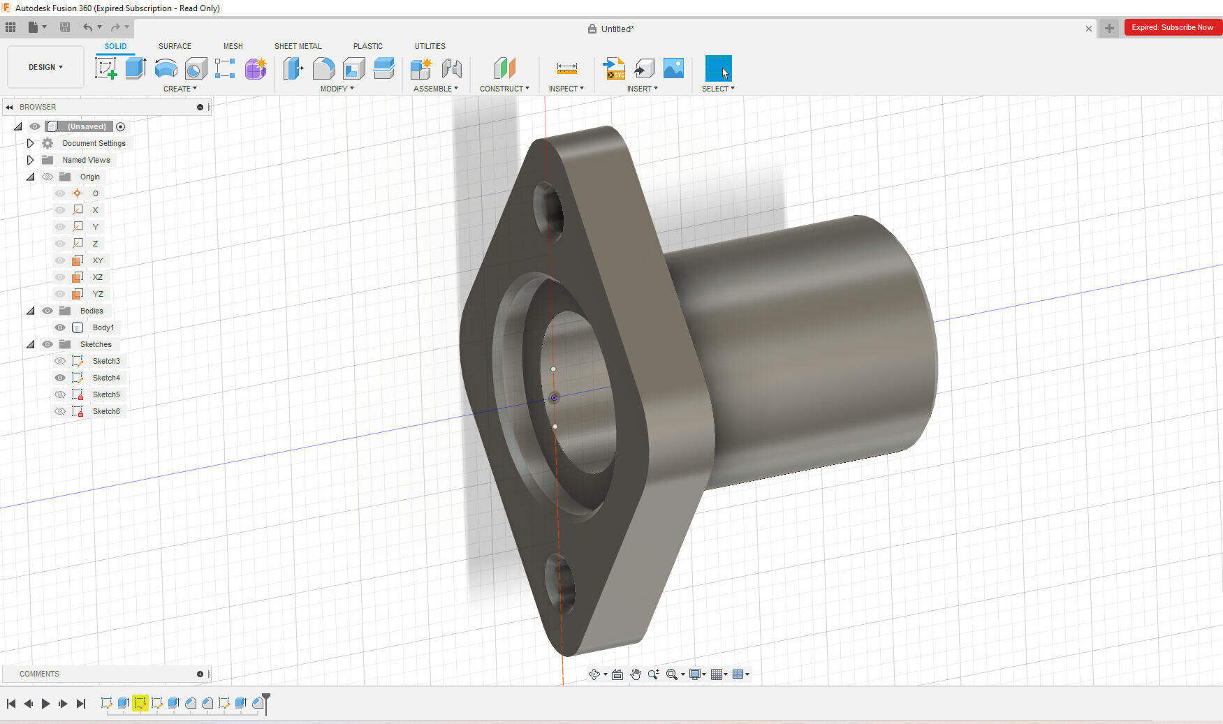
.
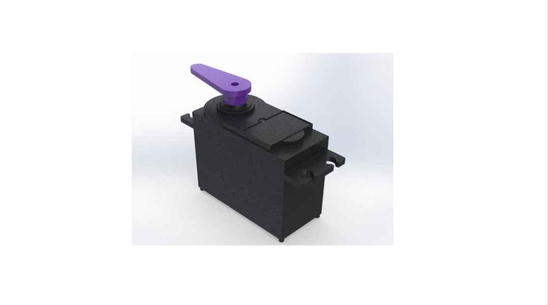
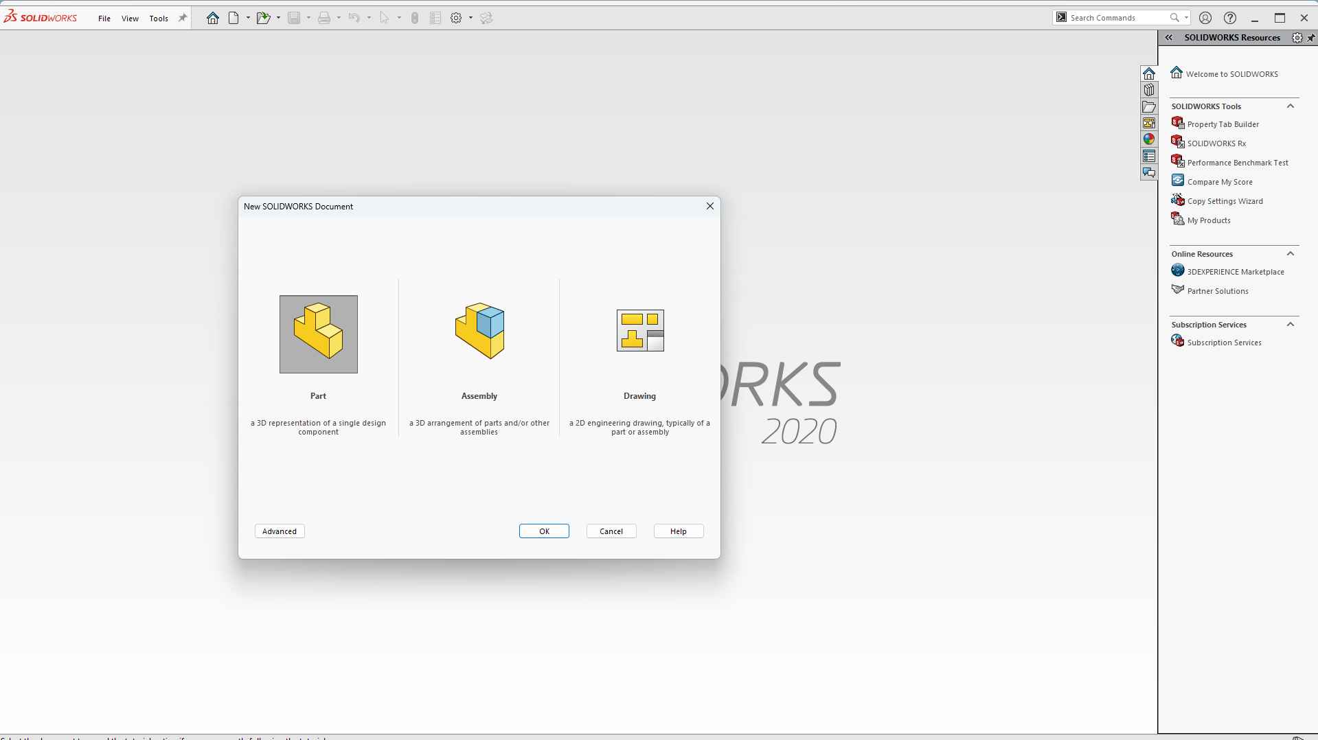
Solid works:
I also try to design a servo motor in solid works. As I am going to use on in my final project for controlling the gas flow towards the burner.
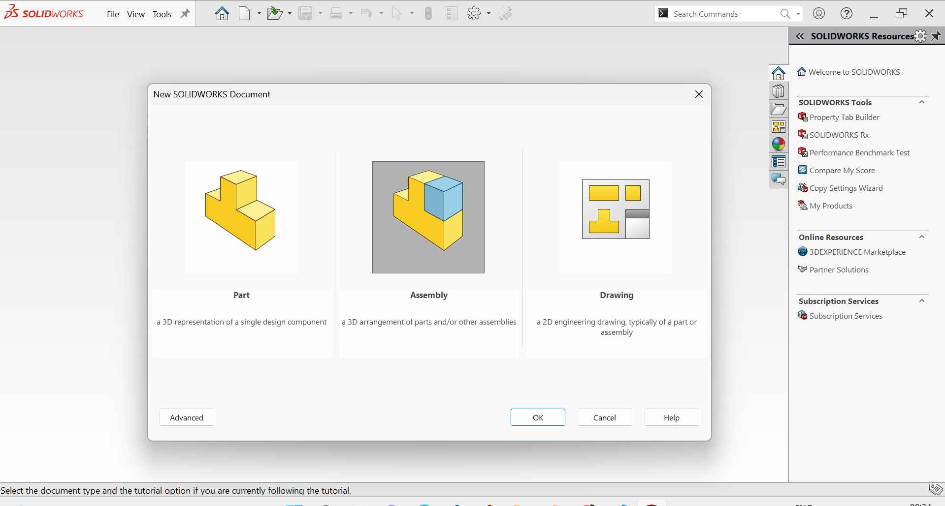
1. I use solid works part design to Design the servo motor parts as follows.
.
2. I first draw the suitable sketch and make it 3D using the Extrude command as you can see.
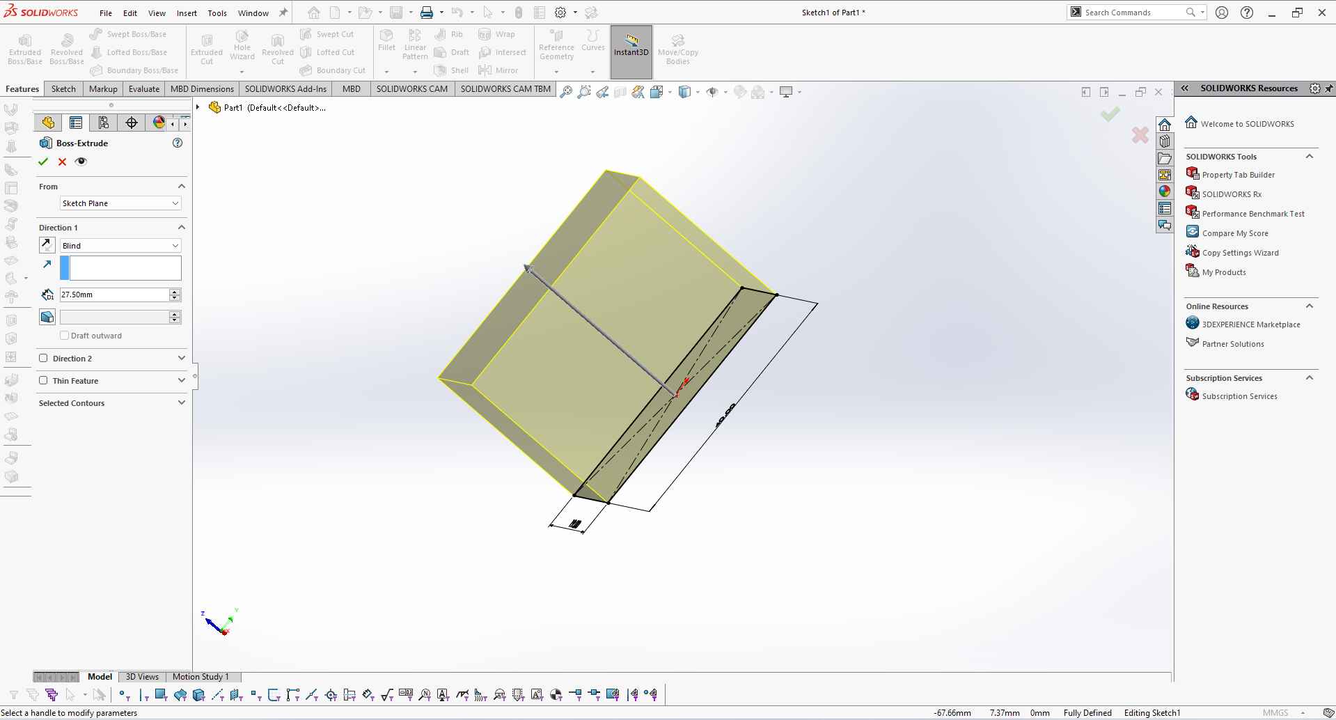
.
3. Then I reuse the sketch command to Draw the sketch to attach nuts and bolts on the servo motor I also use various sketch commands this time like offset, line, construction line, circle, sketch fillet, etc.
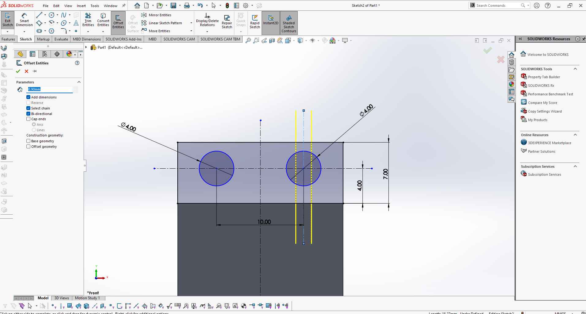
.
4. I use the sketch mirror command to mirror the sketch items I draw and where I where symmetrical sketch parts.
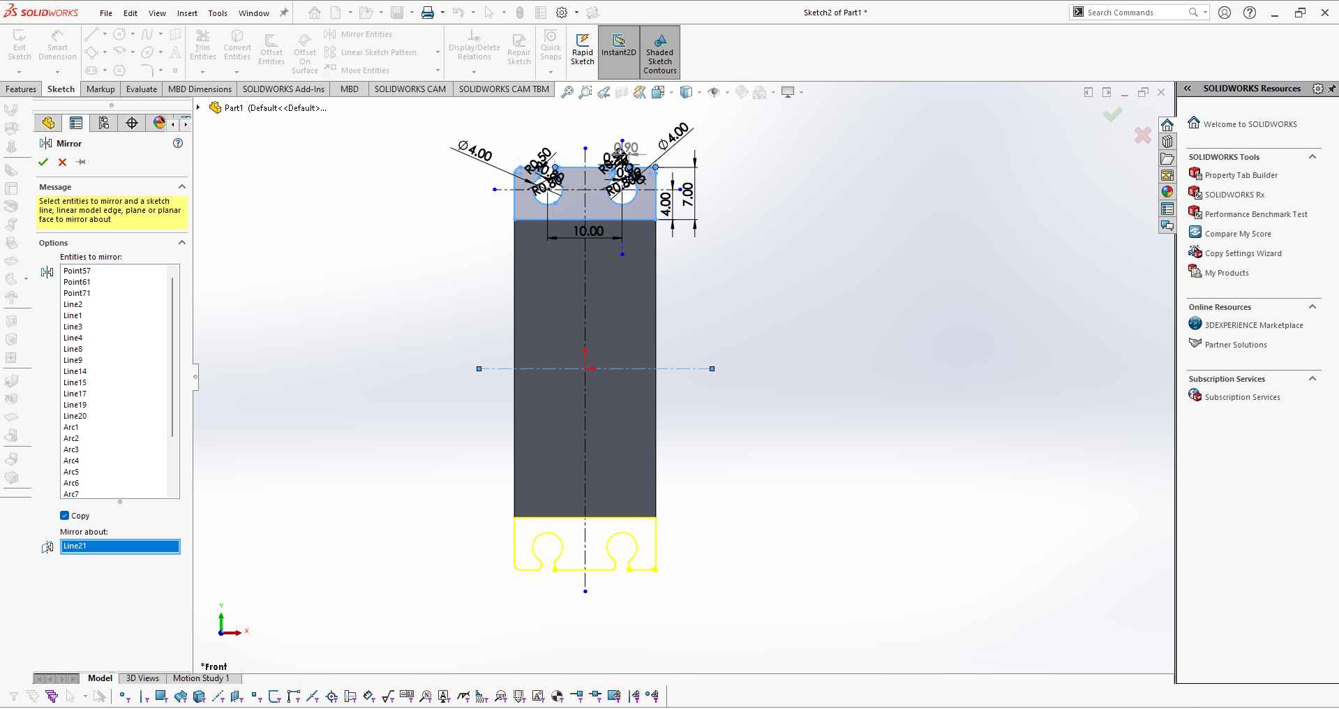
.
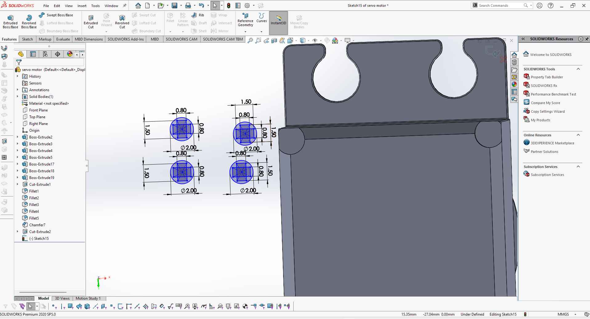
5. After that I redraw the sketch portion on the top of the servo motor using the circle command and use dimension command to give it dimensions.
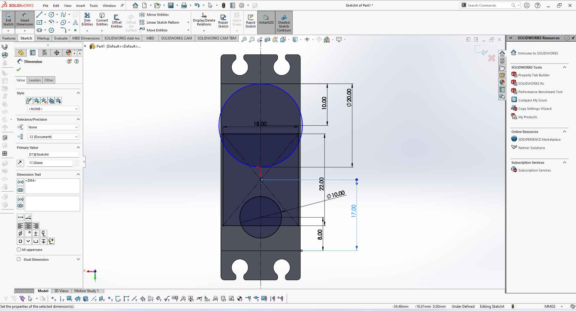
.
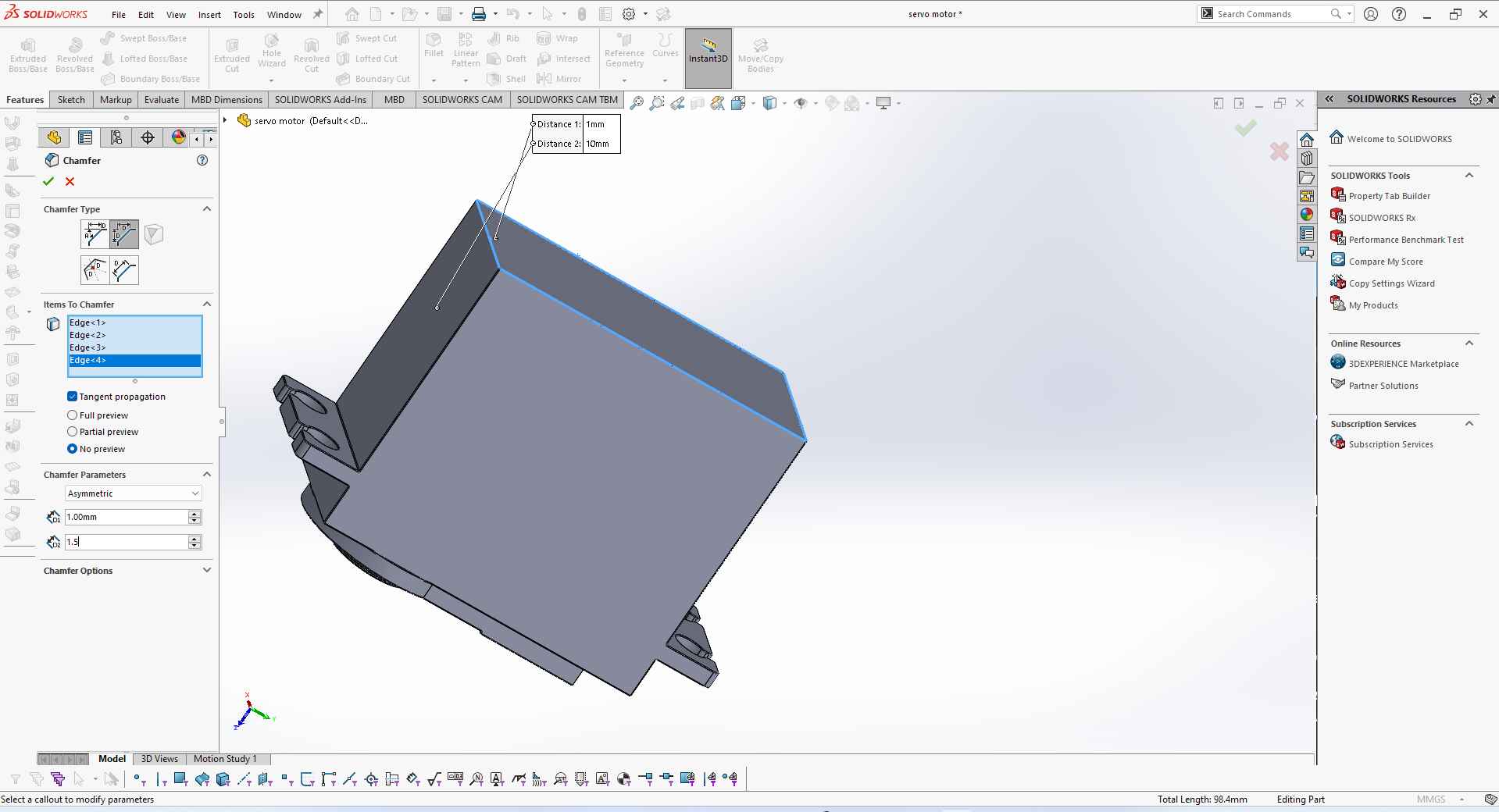
6. Then I use the chamfer command to chamfer the bottom edges of the servo motor body. I also use the fillet command to make sharp edges smooth.
.
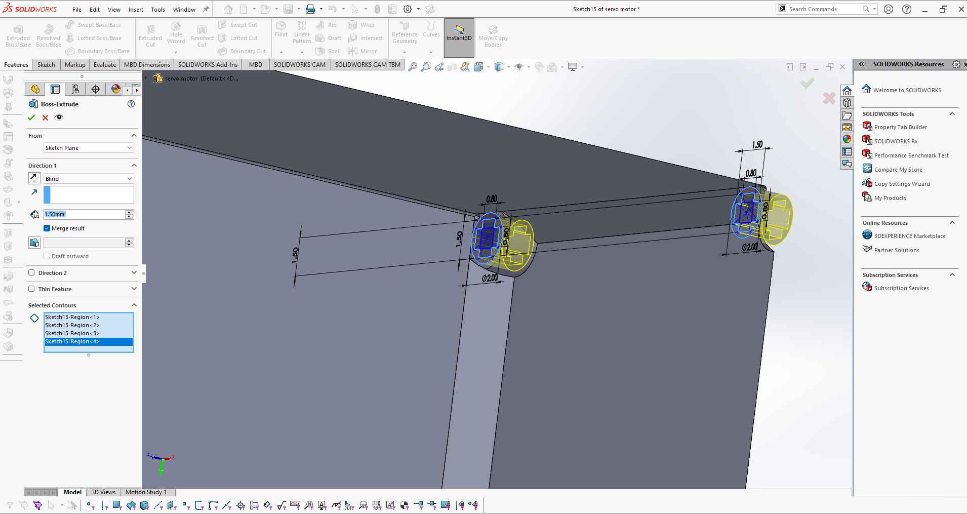
7. I also draw bolts using the sketch command and then extrude them to make 3D.
.
Then I use excrude command to make them 3D and chamfer it to give them bolt like shape.
.
8. Then I again use extrude command to make a bottom output for the wiring of the servo motor.
.
9. Lastly I make a hole using cut-extrude to fold a shaft.
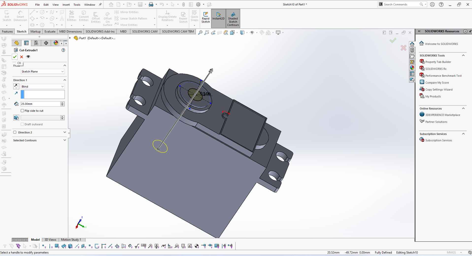
.
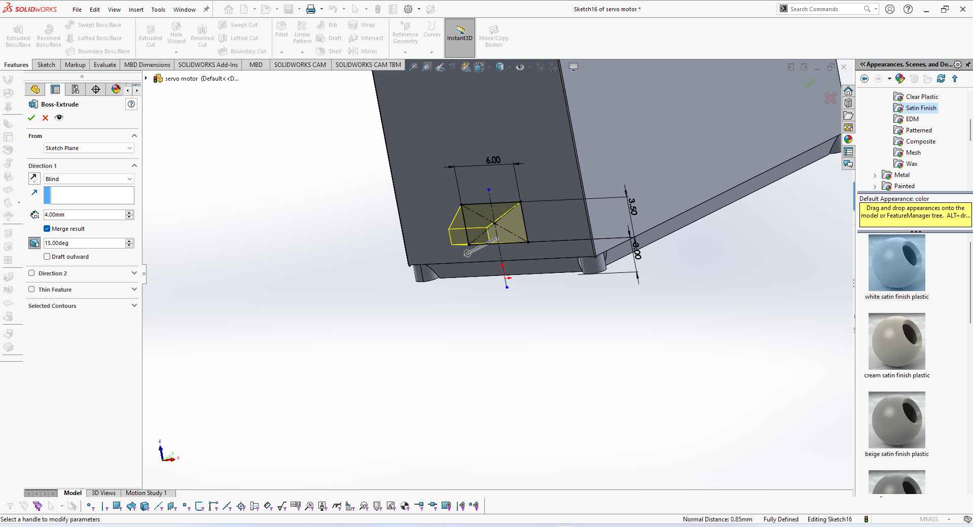
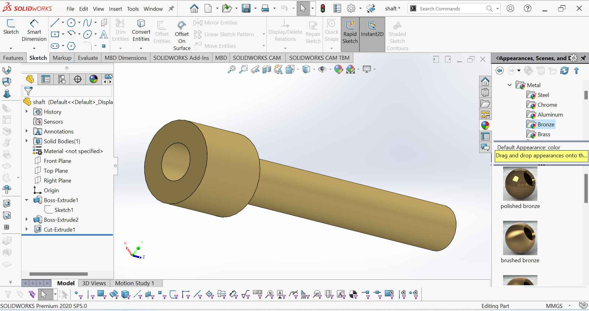
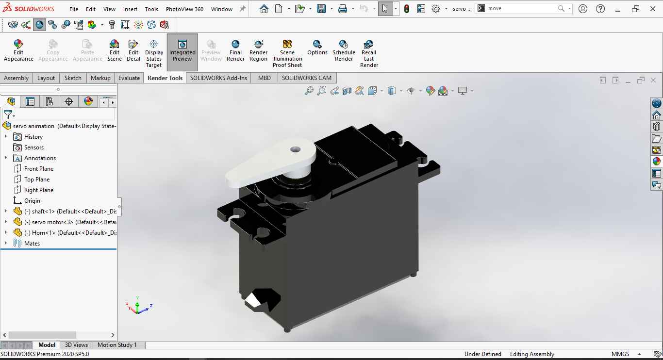
10.finally, I give the appearance to the servo body by assigning the material and colour.
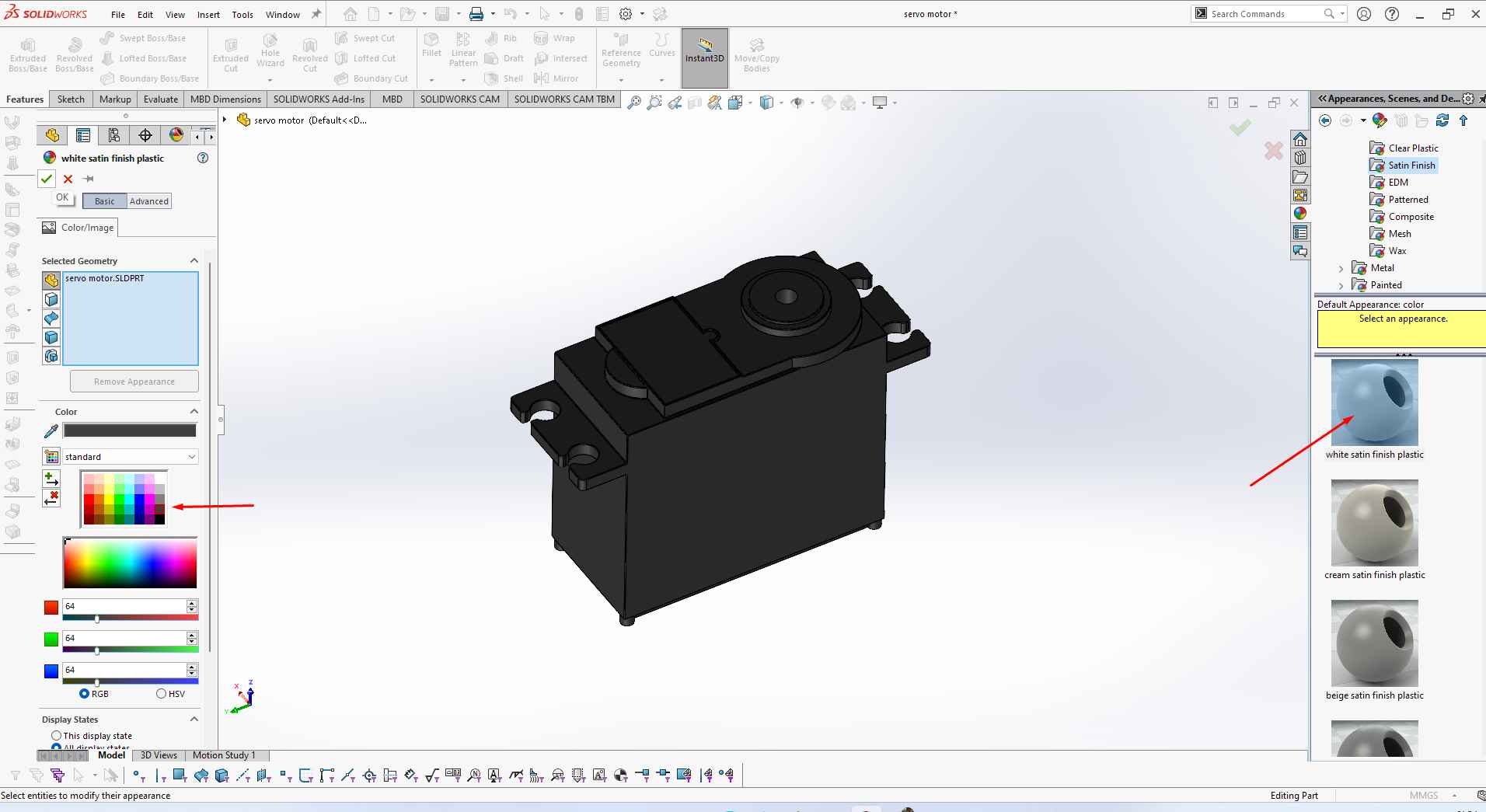
.
As I make the servo body. Similarly, I make other components I need to complete my servo motor.
Servo other components.
1. Servo Horn Sketch.
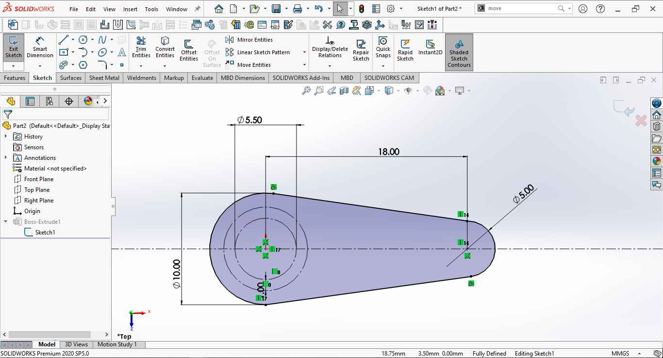
.
2. Exclude the sketch to make it 3D.
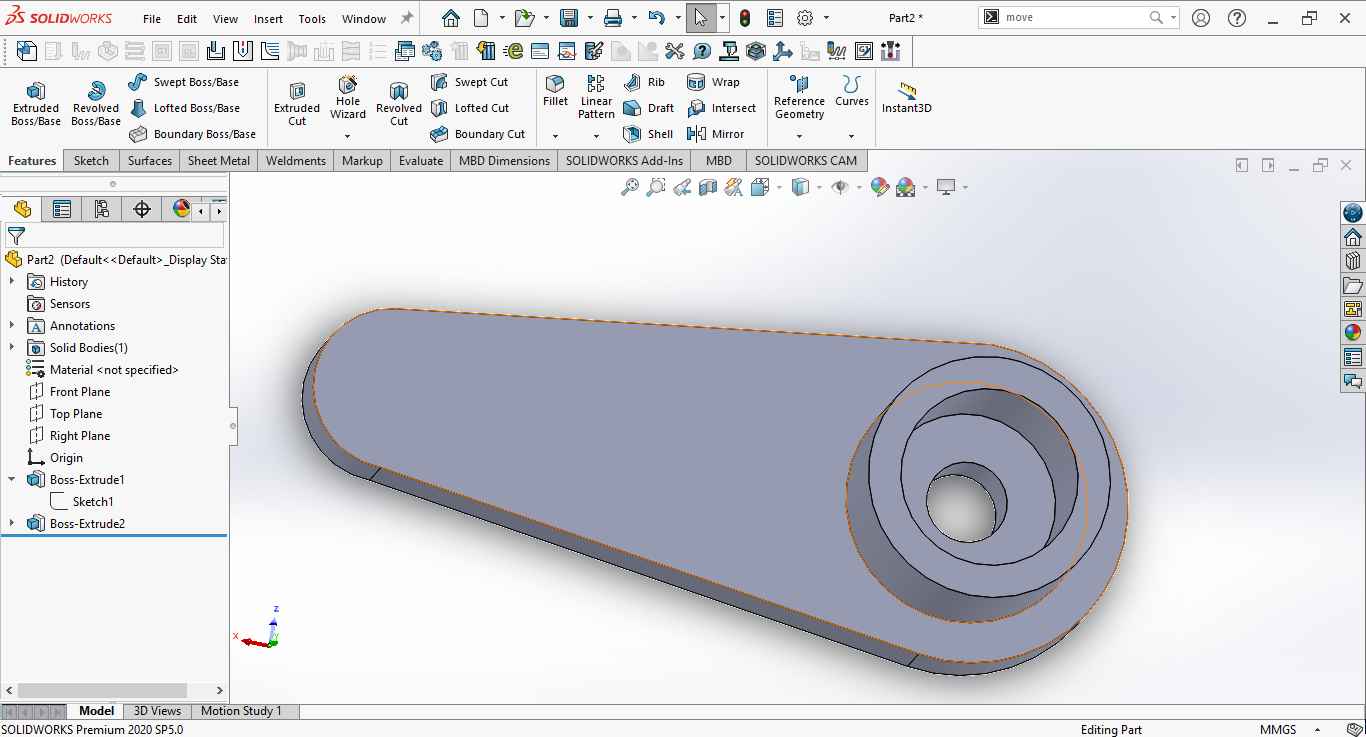
.
3. Similarly I draw the sketch of the shaft and then use Exclude command to make it 3D.
.
Assembly:
1. I use solid works part assembly to assemble the various servo motor parts as follows.
.
2. I use different types of mat commands to assemble the parts such as coincident, concentric, Lock etc.
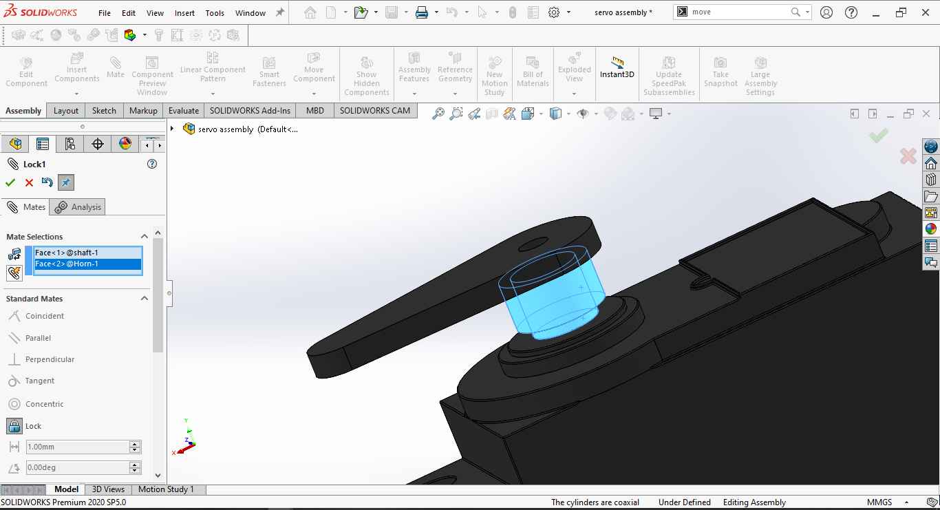
.
3. This is what the final Assembly look like.
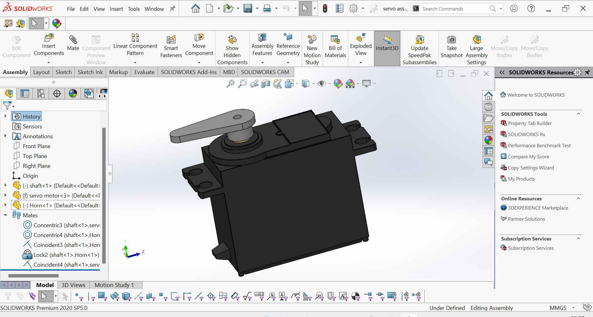
.
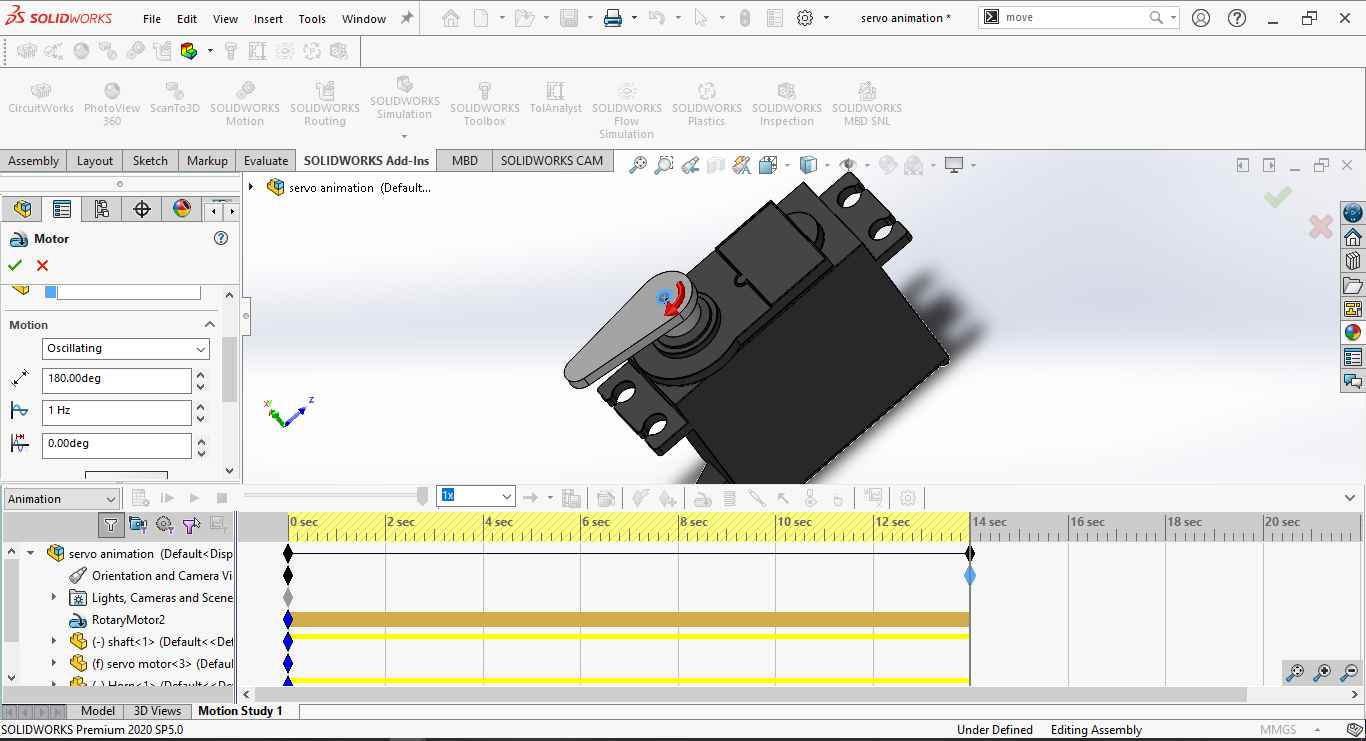
Animation:
For animating the servo motor I use SOLIDWORKS Add-In where I found the SOLIDWORKS Motion feature to animate the servo motor horn motion. Its window looks life follows.
.
I modify the motion to oscillatory motion and frequency to1 Hz and rotate the motor at 180 degrees. and set the timeline to 14 sec.
.
This is the video during the animation as you can see.
This is the final Animation video I served.
Rendering:
Photo View 360:
For rendering in solid works I use photo view 360 Initially . But I don't like it . I try some Initial rendering work Edite the image quality and type as you can see in the picture.
.
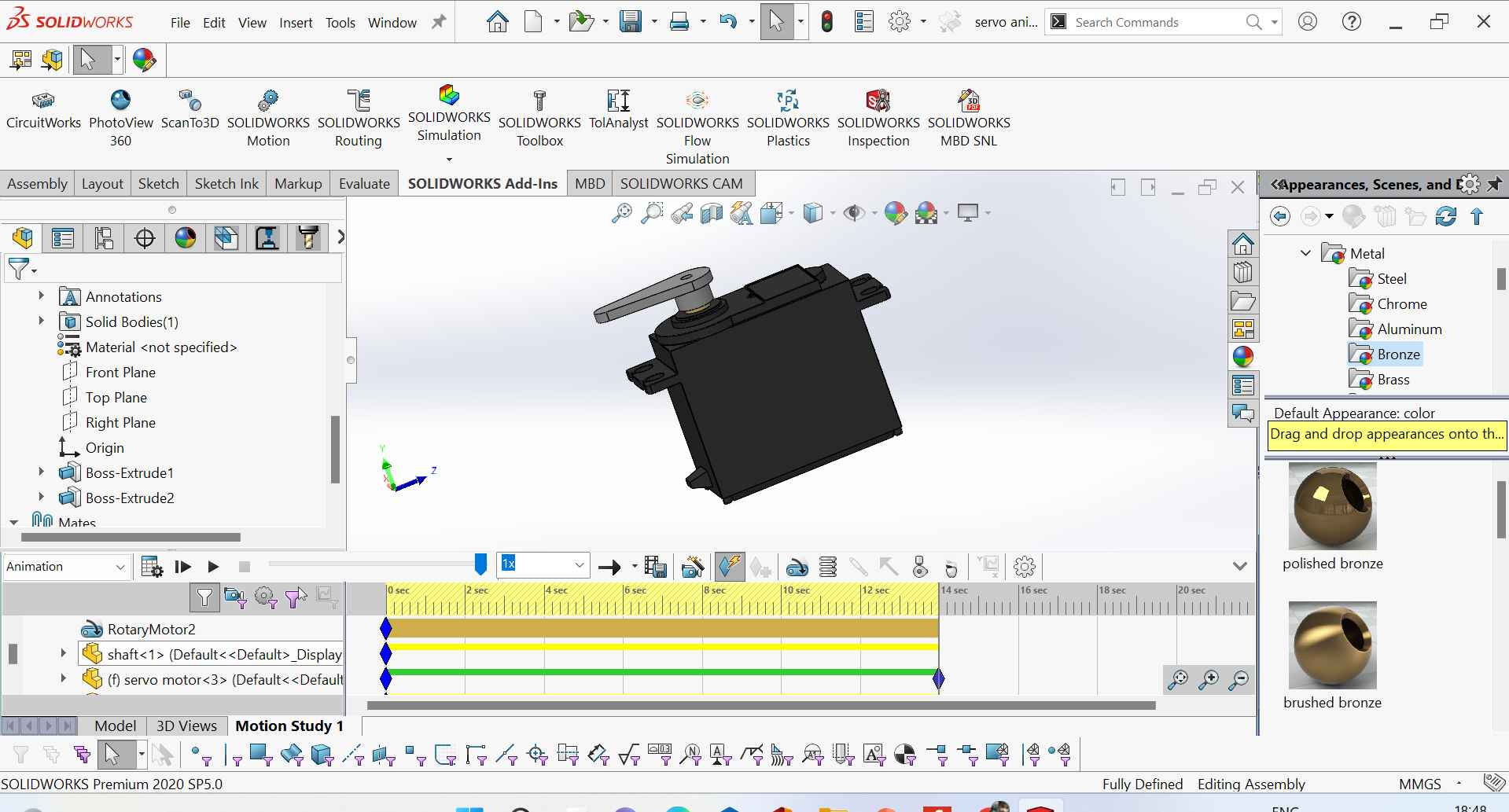
After that, I move to the SOLID WORKS Visualize.
.
I assign the material and colour appearance to Its as you can see in the below image.
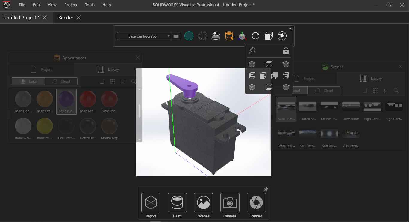
.
This is what the final rendered Image looks like.
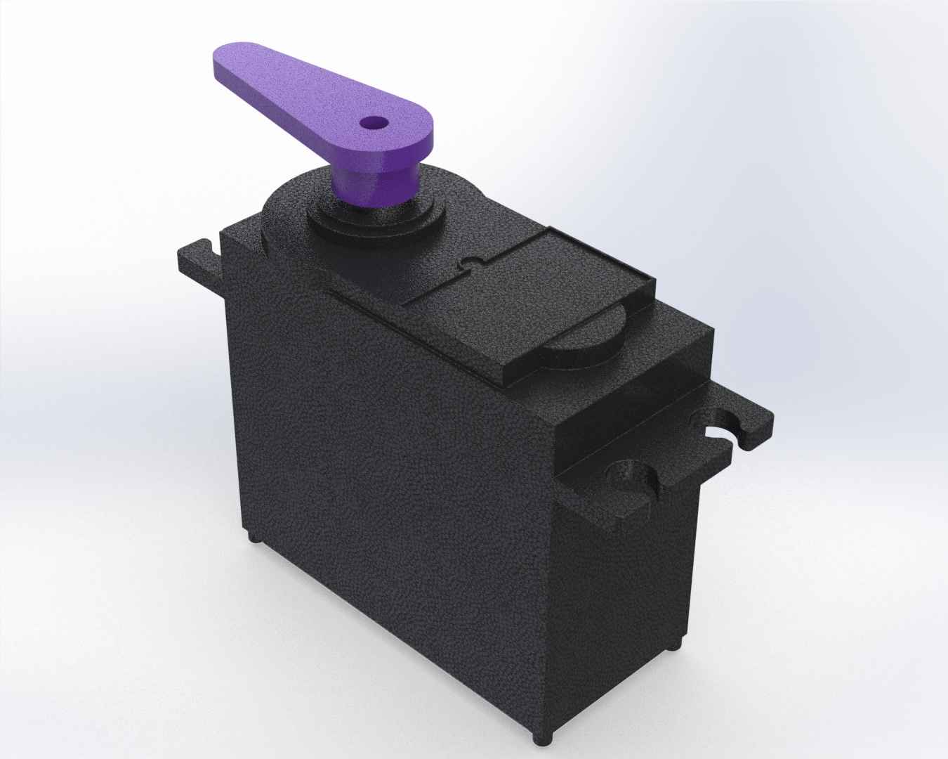
.