The task list for this week:
- Group assignment:
- Send a message between two projects.
- Individual assignments.
- design, build, and connect wired or wireless node(s) with network or bus addresses.
Group assignment:
Communication between project boards:
This Group assignment is about studying the various type of communication proto-call in Embedded systems. For this week's group assignment, we try to communicate between two of our project boards via wi-fi. we use two of our project boards from the lab having ESP32-Wroom microcontrollers to establish communication between them.
Check here to read more about our group assigment.
Individual assignments:
Introduction to Networking and communication:
In an Embedded system Communication is the receiving and transmitting of the data between two or more devices with the help of some formats as well as rules. Communication between electronic devices is like communication between humans. Both sides need to speak the same language.
Data communication:
There are two types of communication mediums:
- Wired
- Wireless
And two types of DATA communication type :
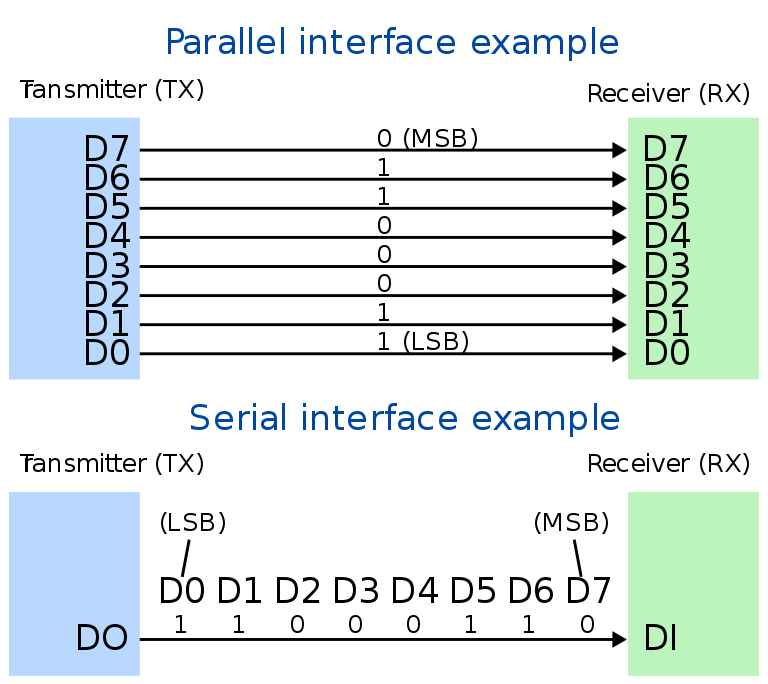
- Paraller communication
- Serial communication
(1) PARALLEL: In parallel communication, all the bits of data are transmitted simultaneously on separate communication lines.
- Used for shorter distance.
- In order to transmit n bit, n wires or lines are used.
- More costly.
- Faster than serial transmission.
- Data can be transmitted in less time.
- It requires only one communication line rather than n lines to transmit data from sender to receiver.
- Thus all the bits of data are transmitted on single lines in serial fashion.
- Less costly.
- Long distance transmission.
Serial communication uses two methods:
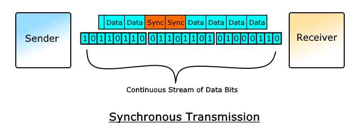
- Synchronous transmission :In this type of serial communication, the sender and receiver are synchronized using an external synchronization clock. Since the data being transmitted has no gaps between them, the receiver identifies the starting of character or data using a common clock pulse. This synchronous clock pulse provides a constant time interval between the data transmission which depends on the frequency of the clock pulse.. Examples of synchronous communication are: I2C, SPI etc.
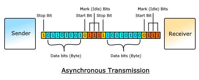
- Asynchronous transmission :In Asynchronous transmission is a type of serial transmission that follows a non-synchronized form of communication. Thus start and stop bits are required in order to intimate the receiver about the beginning and end of the data stream. Examples of asynchronous communication are Universal Asynchronous Receiver Transmitter (UART), CAN etc.
Data Transmission Modes in a network:
Data Transmission mode defines the direction of the flow of information between two communication devices. It is also called Data Communication or Directional Mode.
The data transmission modes can be characterized in the following three types based on the direction of exchange of information:
- Simplex
- Half-Duplex
- Full Duplex
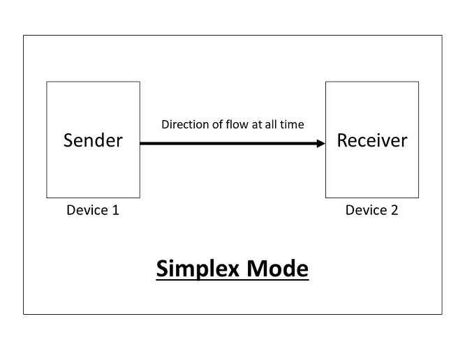
(1)Simplex:Simplex is the data transmission mode in which the data can flow only in one direction, i.e., the communication is unidirectional.
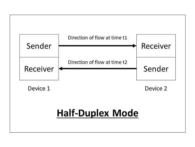
(2)Half-Duplex:Half-Duplex is the data transmission mode in which the data can flow in both directions but in one direction at a time. It is also referred to as Semi-Duplex.
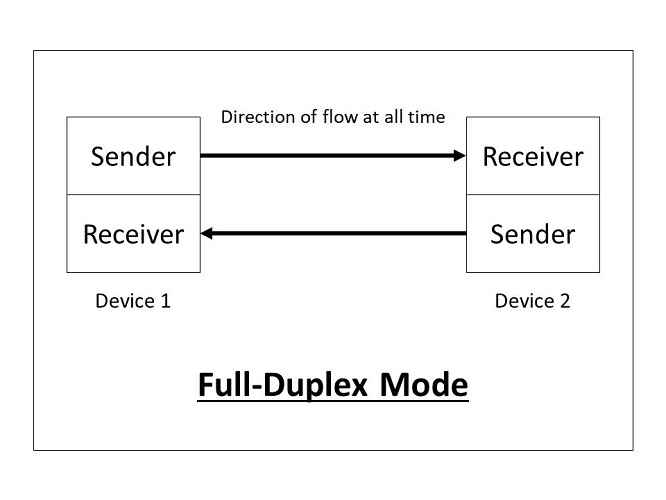
(3) Full-Duplex:Full-Duplex is the data transmission mode in which the data can flow in both directions at the same time. It is bi-directional in nature.
Bit rate & Baud Rate Concepts:
1. Bit rate :
Bit rate is the number of binary bits (1s or 0s) transmitted per second.
Bit rate = number of bits transmitted/ total time (in seconds)
The bit rate can also be defined in terms of baud rate:
Bit rate = Baud rate x bits per signal or symbol
2. Baud rate :
Baud rate is the rate at which the number of signal elements or changes to the signal occurs per second when it passes through a transmission medium. The higher a baud rate is the faster the data is sent/received
Baud rate = number of signal elements/total time (in seconds)
Example:
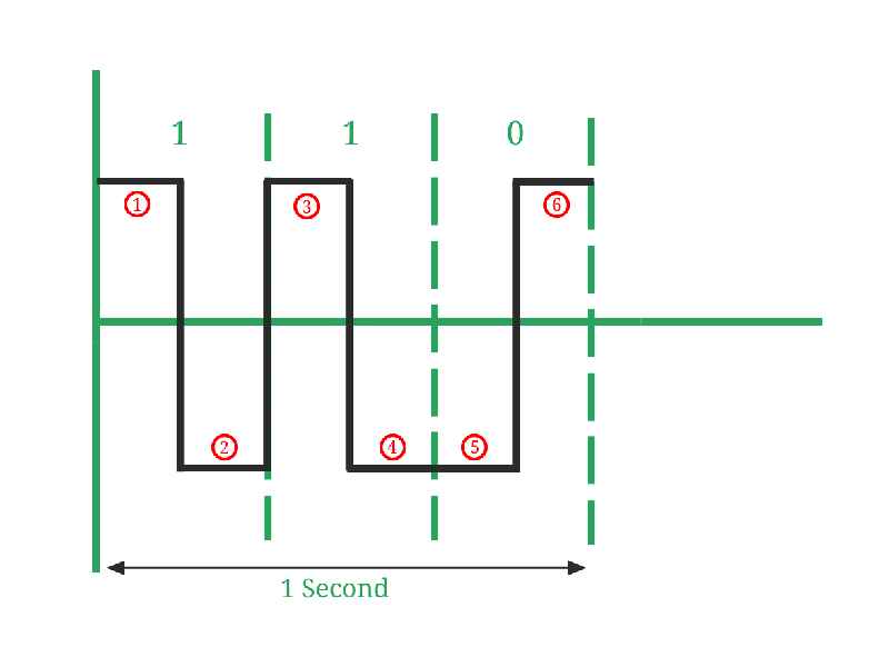
In Image , Number of signal elements (marked in red color) = 6, Number of bits transmitted (1, 1, 0) = 3. So, Here Bit rate = 3/1 = 3 bits per second. and, Baud rate = 6/1 = 6 baud per second.
Communication Protocall:
Communication Protocols are a set of rules that allow two or more communication systems to communicate data via any physical medium.In Embedded systems, communication protocols hold a special place as it opens up ways to efficiently exchange data between devices. A Communication protocol is a set of rules agreed upon by both the sender and receiver on the bases of data packed., bits constituting a character,data begins and ends.
Types of Communication Protocall:
There are two types of communication protocols :
- Inter System Protocol.
- Intra System Protocol
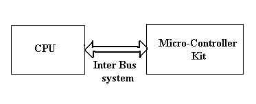
(1)Inter System Protocol:The inter-system protocol using to communicate the two different devices. Like communication between computer to microcontroller kit. The communication is done through an inter bus system.
The different categories of intersystem protocol mainly include the following.
- UART Protocol:UART stands for a universal asynchronous transmitter and receiver. UART Protocols is a serial communication with two wired protocols. The data cable signal lines are labeled as Rx and Tx. Serial communication is commonly used for transmitting and receiving the signal. It is transferred and receives the data serially bit by bit without class pulses. The UART takes bytes of data and sends the individual bits in a sequential manner.
- USART Protocol:USART stands for a universal synchronous and asynchronous transmitter and receiver. It is a serial communication of a two-wire protocol. The data cable signal lines are labeled as Rx and TX. This protocol is used to transmitting and receiving the data byte by byte along with the clock pulses. It is a full-duplex protocol that means transmitting and receiving data simultaneously to different board rates. Different devices communicate with microcontroller to this protocol.
- USB Protocol:USB stands for universal serial bus. Again it is a serial communication of two-wire protocol. The data cable signal lines are labeled D+ and D-. This protocol is used to communicate with the system peripherals.USB protocol is used to send and receive the data serially to the host and peripheral devices.USB communication requires driver software that is based on the functionality of the system.
Increase in components lead to circuit complexity and increase in power consumption. Intra system protocol promises secure access of data from the peripherals.
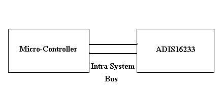
The different categories of intrasystem protocol mainly include the following.
- SPI Protocol:SPI stands for the serial peripheral interface. It is one of the serial communication protocol developed by Motorola. Sometimes SPI protocol is also called a 4-wire protocol. It requires four wires MOSI, MISO, SS, and SCLK.SPI protocol used to communicate the master and slave devices. The master first configures the clock using a frequency.
- CAN Protocol:CAN stands for the controller area network. It is a serial communication protocol. It requires two wires CAN High (H+) and CAN low (H-). It was developed by the Robert bosh company in 1985 for in-vehicle networks. It is based on a message-oriented transmission protocol.
- I2C Protocol:I2C stands for the inter-integrated circuit and it requires only two wires connecting all peripherals to the microcontroller. I2C requires two wires SDA (serial data line) and SCL (serial clock line) to carry information between devices. It is a master to a slave communication protocol. Each slave has a unique address. The master device sends the address of the target slave device and reads/writes the flag.
I2C Bus Communication:
What is I2C ?
Introduction to I2c communication .
I2C stand for Inter-Integrated circuit bus it is also called I2C, IIC as well, TWI ( Two-Wire Interface) is a subset of I2C protocol.I2C is a serial bidirectional Low speed 2 wire interface . Developed by Phillips in 1982 for the telephonic industry. but nowadays every semiconductor manufacturer is useless due to its low cost and less logic gate count and 2 wire requirement. It is suitable over short distances over 1meater.
I2c Interfaces
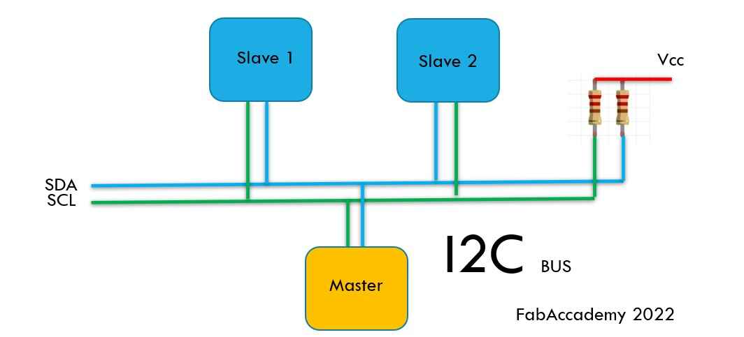
I2C protocall block digram.
I2C protocol uses two wires for data transfer between devices: Serial Data Line (SDA) and Serial Clock Line (SCL). Any device connected to the bus must act as a master or a slave. The master generates a clock signal and initiates a data transaction by addressing a slave on the bus and telling whether it wants to transmit or receive data. Each Slave has its own unique address starting with 7-bit and can attach up to 128 devices max for a 7-bit address also some new protocol fallows up to a 10-bit address which extends the device connectivity up to 1024 devices max.
Open-Drain Outputs: The two pull-up resistance are always connected to the SDA and SCK with VDD because SDL and SCL pins of the master device are designed with the transistors in the open state, so data transfer is possible only when these transistors are conducted.
I2C Waveform Characteristics:
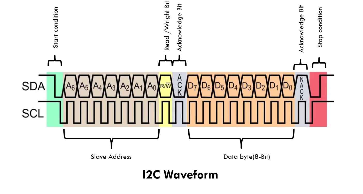
Bit transfer:No. of bits transfer per clock pulse is called bits transfer. One data bit is transferred during each clock pulse.
Start and Stop Bit Condition:All I2C transactions are initiated with the start condition. And end with a stop condition. when the master micro-control wants to talk to a slave it activates the start condition.
Start Condition:
- Master SDA=HIGH to LOW
- Master SCL=Hold HIGH
STOP Condition:
- Master SDA=LOW to HIGH
- Master SCL=Hold HIGH
- From Idle state (no clock)
- Master SCL=SDA=HIGH.
Read /Write Bit:R/W bit together with slave address forms control byte .This bit inform the slave a master wants to read or wright. .
- R/W:HIGH =Read data request.
- R/W:LOW =Data will be sent.
- ACK= =Acknowledge=LOW(zero)
- NACK =Acknowledge=HIGH(one)
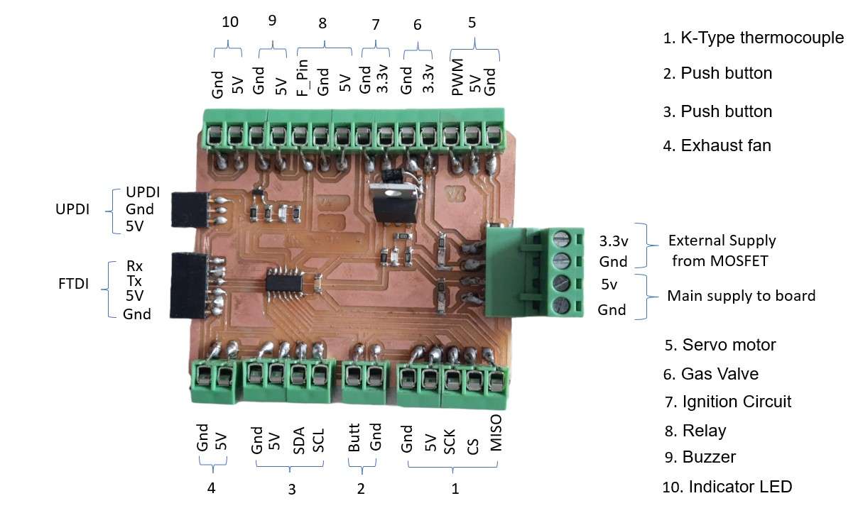
Board I am using this week:
For this week I am continuing with my final project bord. I make in my output devices assignment. I am using It as a master device to communicate with the LCD display with the I2c module. Following is the schematic and board design in the eagle of my final board from week 10.
Scametic Designe:
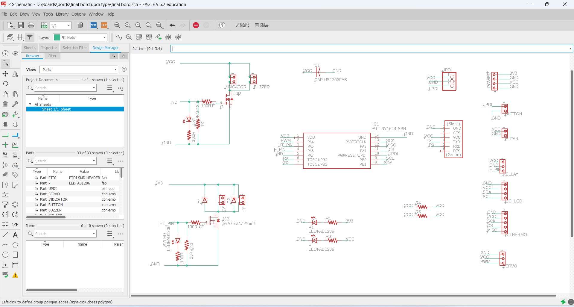
Final board piout and funcanality.
Board design:
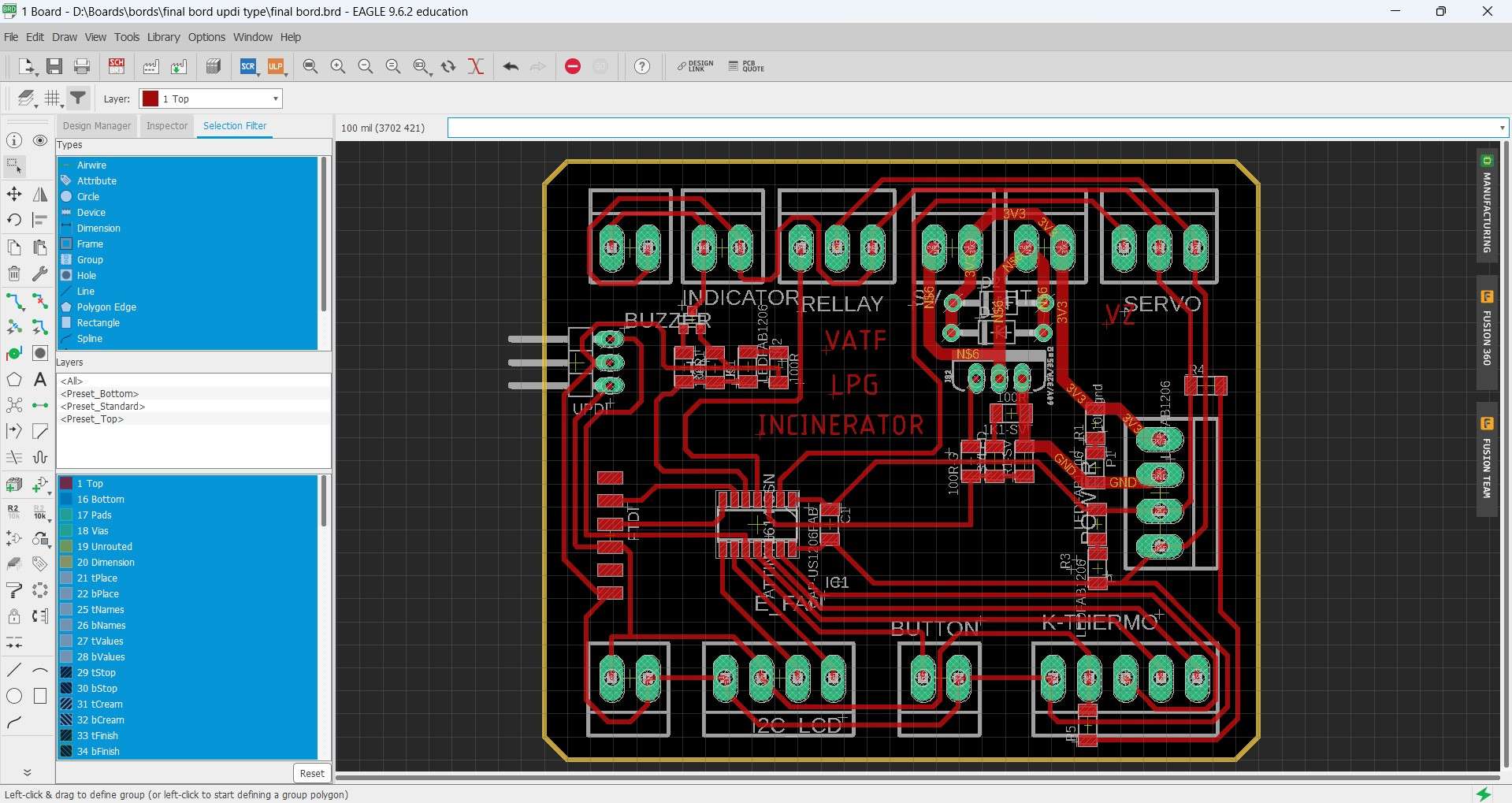
Final board piout and funcanality.
Final Board V1:
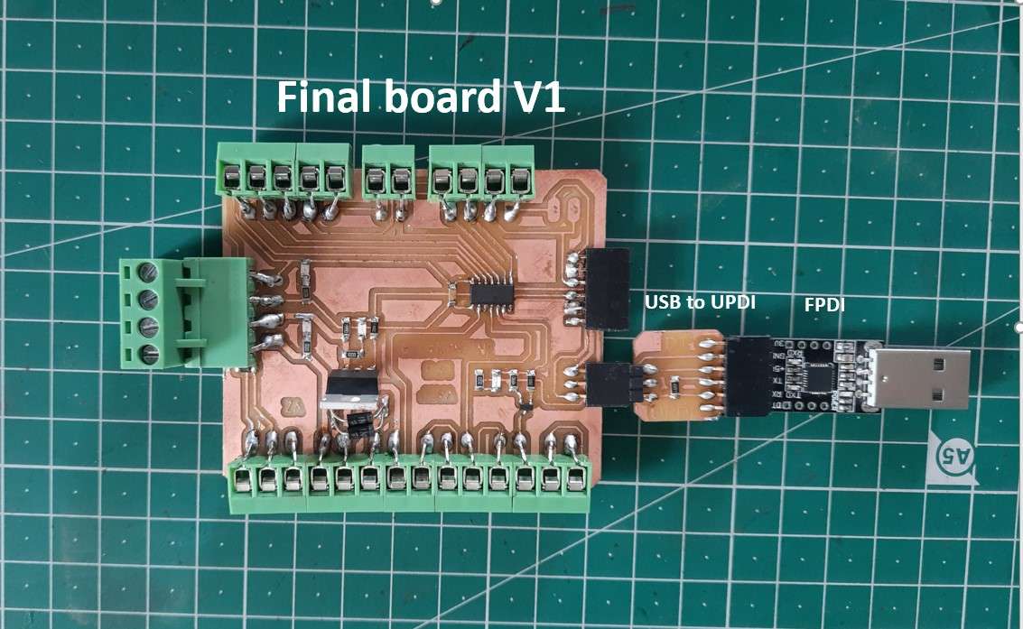
Final board piout and funcanality.
Final Board V1:
Final board piout and funcanality.
I2C bus with LCD display with I2c module (PCF8574 ) and my final bord. :
I2C bus in ATtiny1614. :
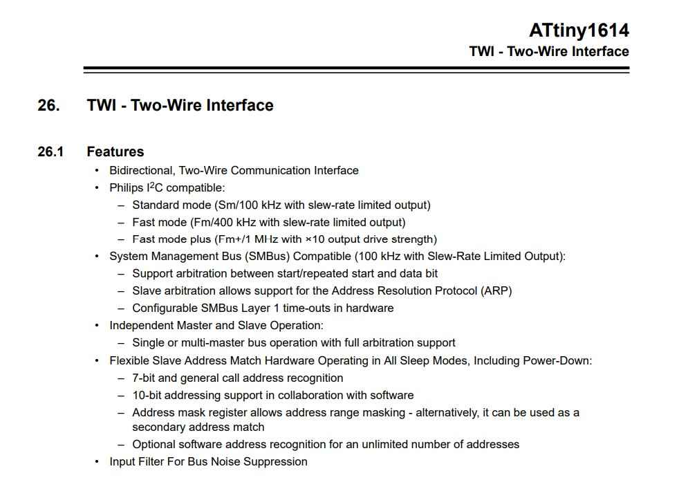
Attiny1614-TWI.
To demonstrate I2c communication .I decided to use my final project board(ATtiny1614).I started searching the I2c protocol in ATtiny 1614 IC .But it was not there with same name.
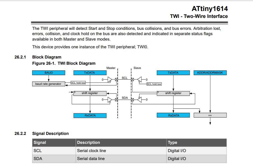
TWI-block digram.
I found TWI - Two-Wire Interface protocol which I then come to know is a subset of a I2C communication. I read a bit and ensure the I2C bus works and proceed forward.
I2C Interface Adapter Module.
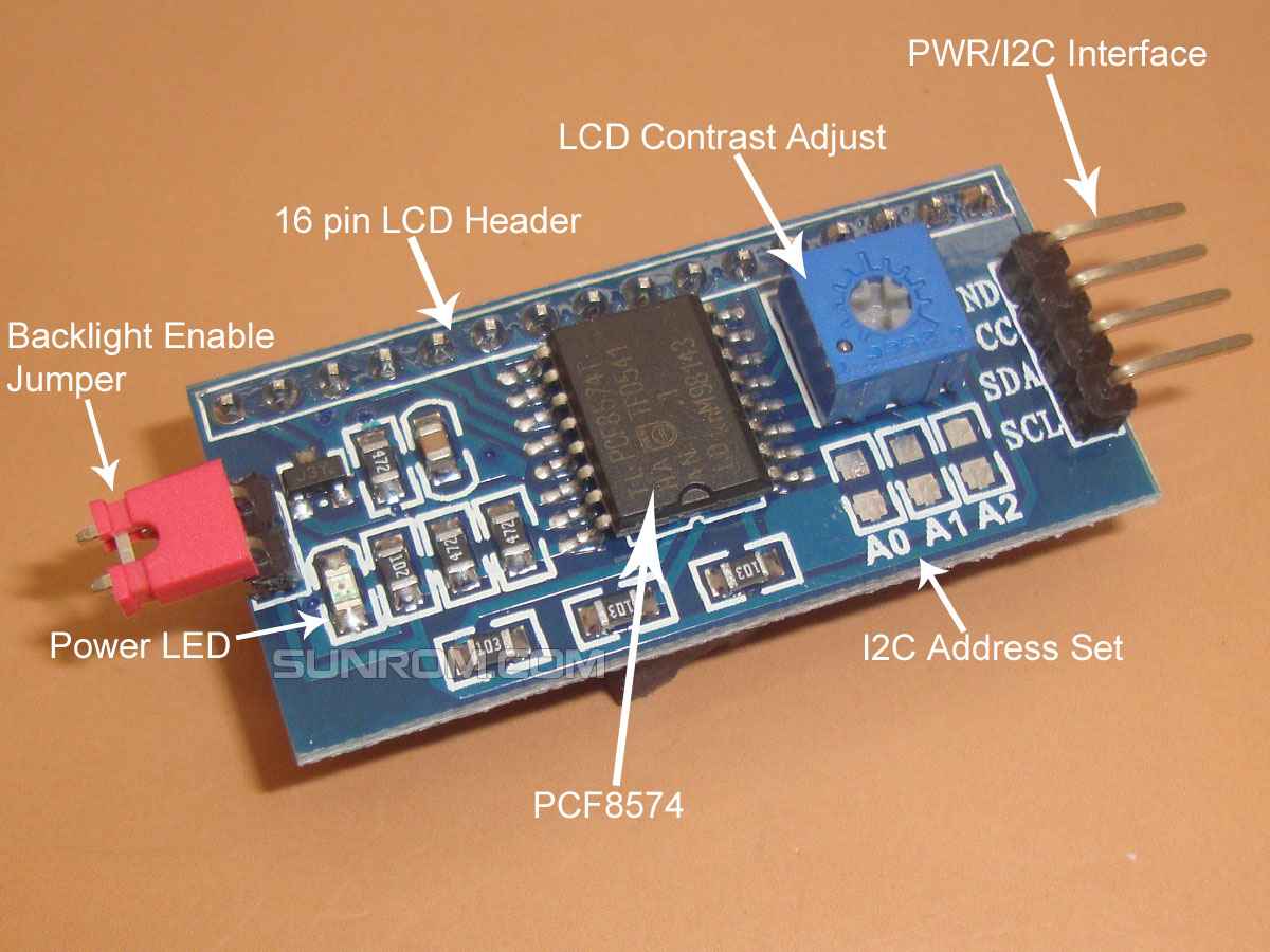
I2C Interface Adapter Module.
I2C Interface Adapter Module is used for 16x2 LCD Display.It uses the PCF8574T IC chip which converts I2C serial data to parallel data for the LCD display. Also this interface module simplifies 16 header pins out of 16x2 Liquid Crystal display into only 4 wires SDA, SCL, Vcc and Gnd.
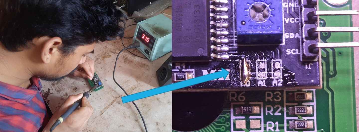
It also provides division where one can change the address of a module just by soldering one of the connections.
Chenging I2C address.
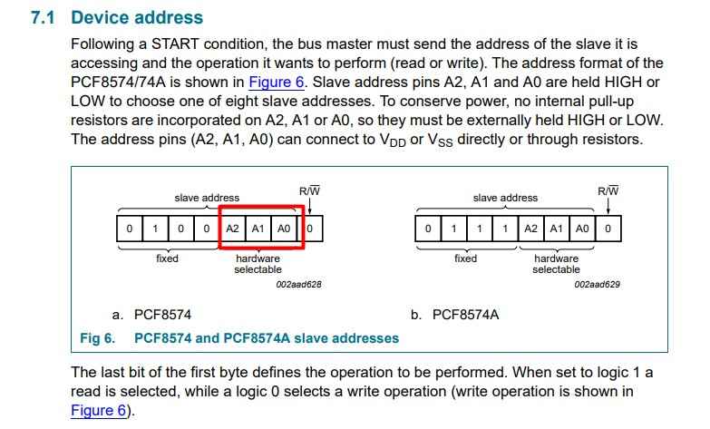
Device address.
To know about it further I read the data sheet of PCF8574T IC . where I come to know that the last 3 bits of the Slave address are hardware selectable. So I can change the Address of one of the modules externally by LOW down the one of address bit Bit among A0, A1, A2.
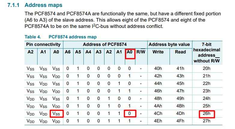
Address maps.
There are 8 address combinations that can be found among these 3 connections.I solder A0 bit of one of my modules to change its Address. According to the datasheet, the changed combination should give 26h as a 7-bit hexadecimal address.
Changing address of I2C module.
I2C Serial BUS connection .
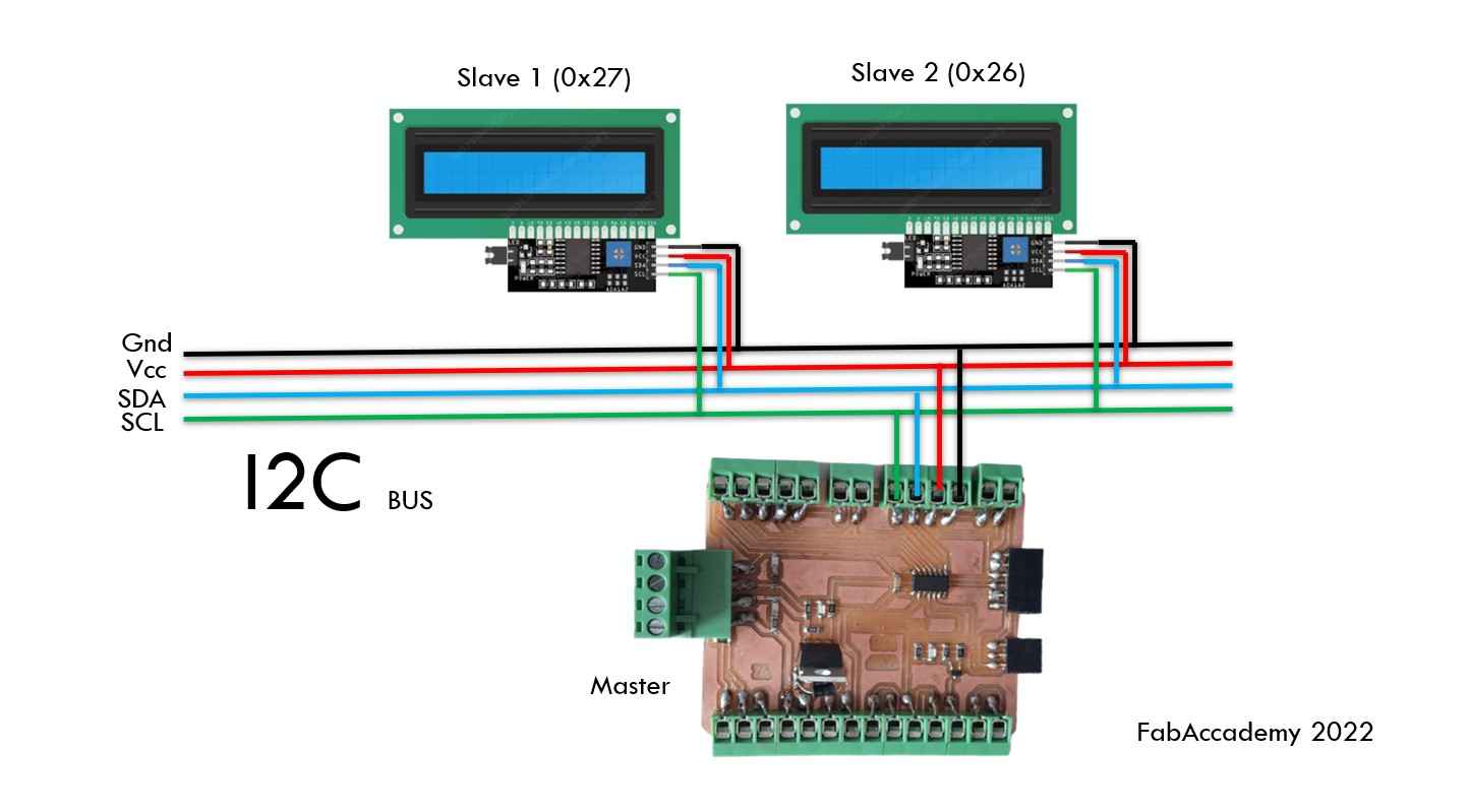
I2C Serial BUS connection.
Above I show how I connect I2C Interface Adapter Module as slave in the I2C Serial BUS connection with my board as master device.
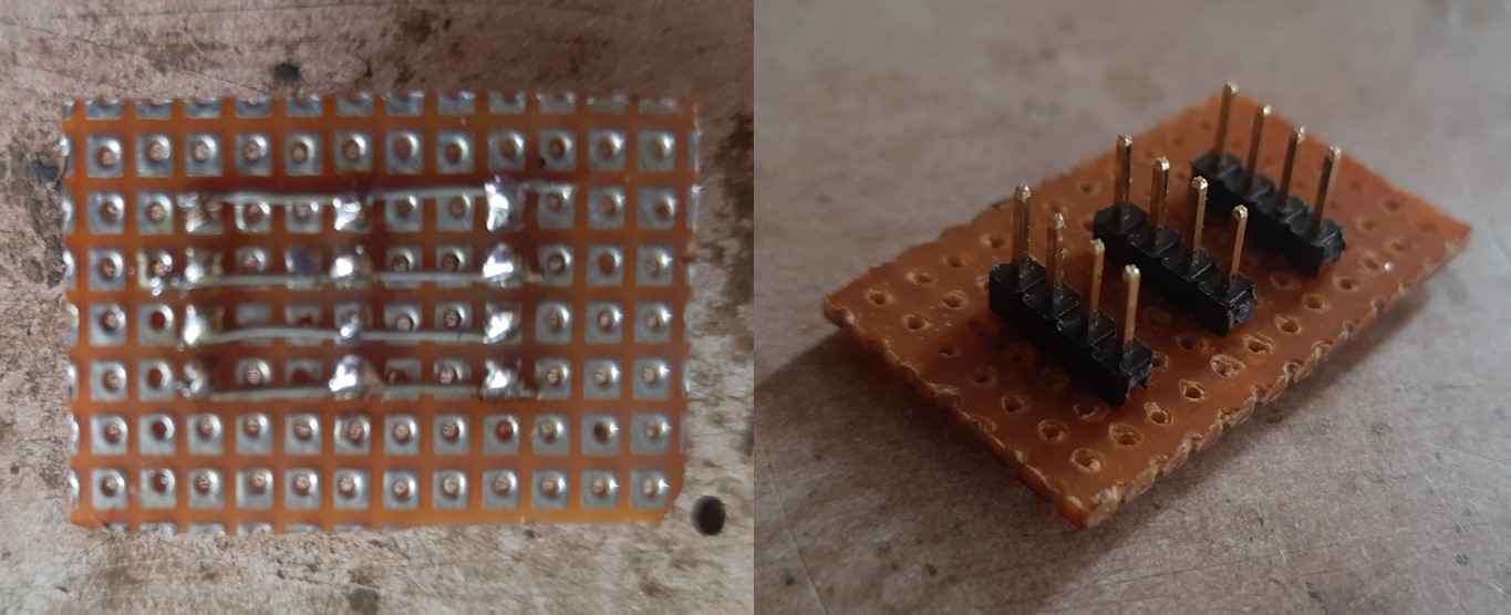
Parallel connector.
To connect this module physically.I make a small 4-pin header connector. Using a through-hole board and header pin connector and soldering them in parallel.
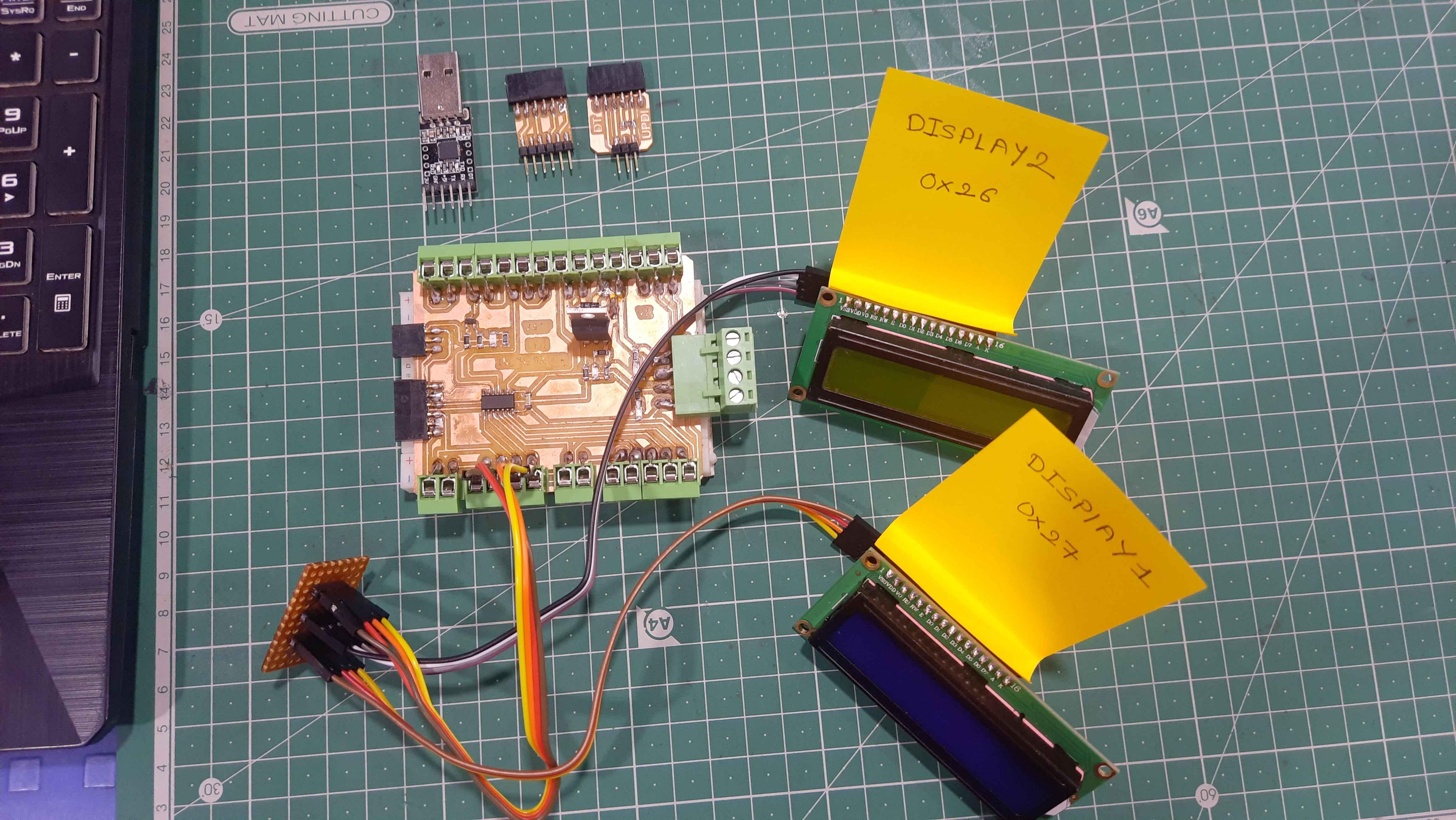
I2C Serial BUS connection setup.
Here is the setup ready for the I2C protocol between 2 I2C Interface Adapter Module with 16x2 LCD Display as Slave devise and my Board as Master devise.
Scanning I2C address.
For confirming the address once again I refer to this blog from last-minute engineers. Where I found this code for Determining the I2C Address.
I2C Address Scanning code.
Scanning I2C Address.
After scanning the Address of I2C Modules I found I scan two Devices of address as follows.
- Found address:38(0x26)
- Found address:39(0x27)
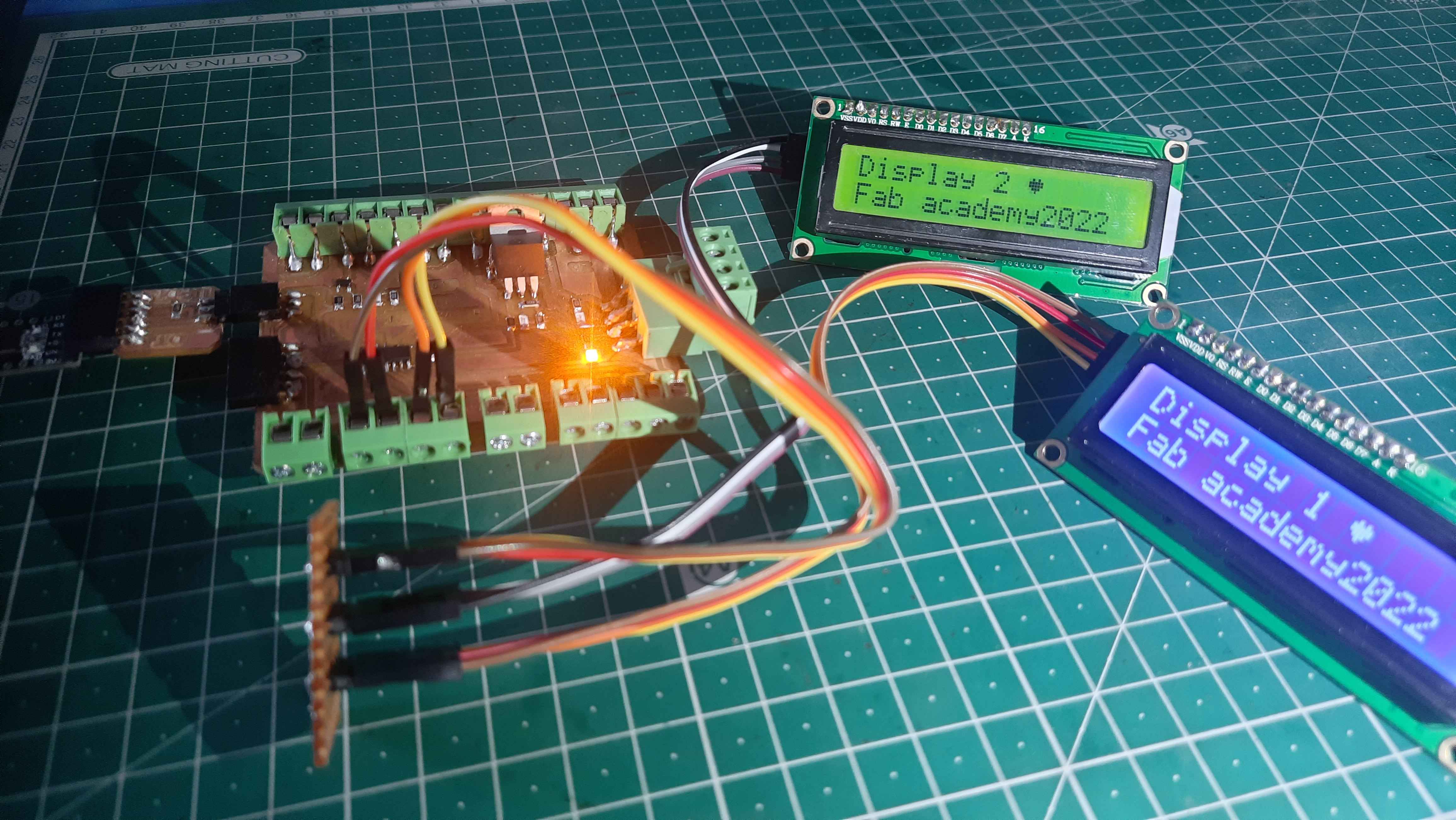
I2C Communication using 16x2 LCD Display.
Now for making I2C communication between the 16×2 LCD Display and my board. I use the same code from the Input devices assignment for the LCD display code. Customizing it for 2 Individual LCDs with two different addresses naming them LiquidCrystal_I2C lcd1 & LiquidCrystal_I2C lcd2 And define each lcd.print() function to display ,Display1 and Display 2 on LiquidCrystal_I2C lcd1 and LiquidCrystal_I2C lcd2 respectively.
Code I use to display the display no.of individual display.
display the display no. of individual display.
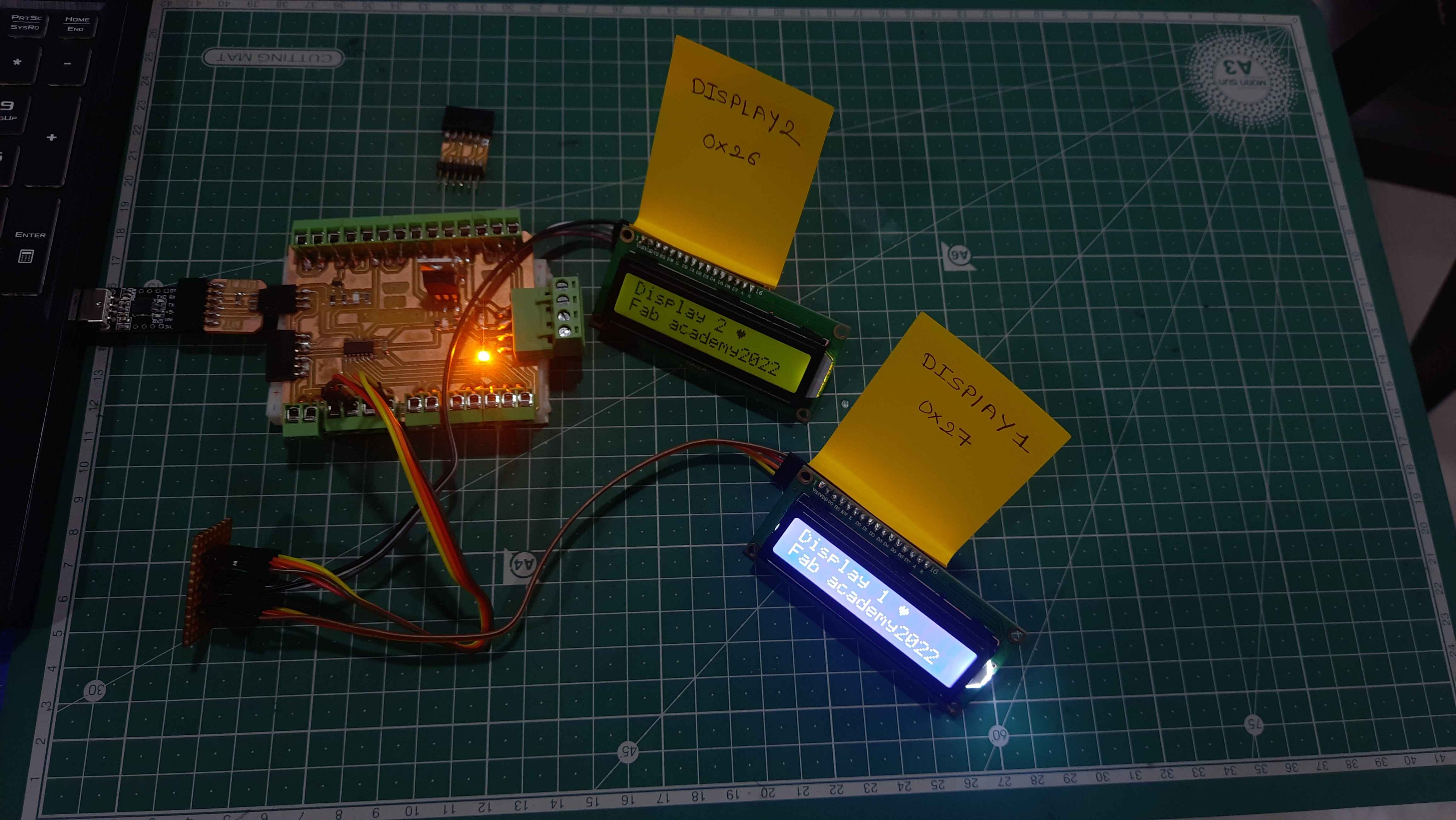
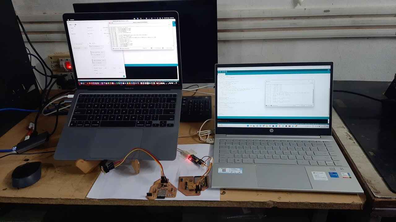
Output.
After establishing the I2C communication between two LCDs display successfully and confirm the display address with display no. ( luckily it was the same) . I decided to try to print the temperature on each Display using the K-type thermocouple.So I custom the code to print degree celsius on Display 1 and Fahrenheit on Display 2.
Code I use to Display temprature in degree celsius and fahrenheit on display1 & display2 respectively.
Display temprature in degree celsius and fahrenheit on display1 & display2 respectively.
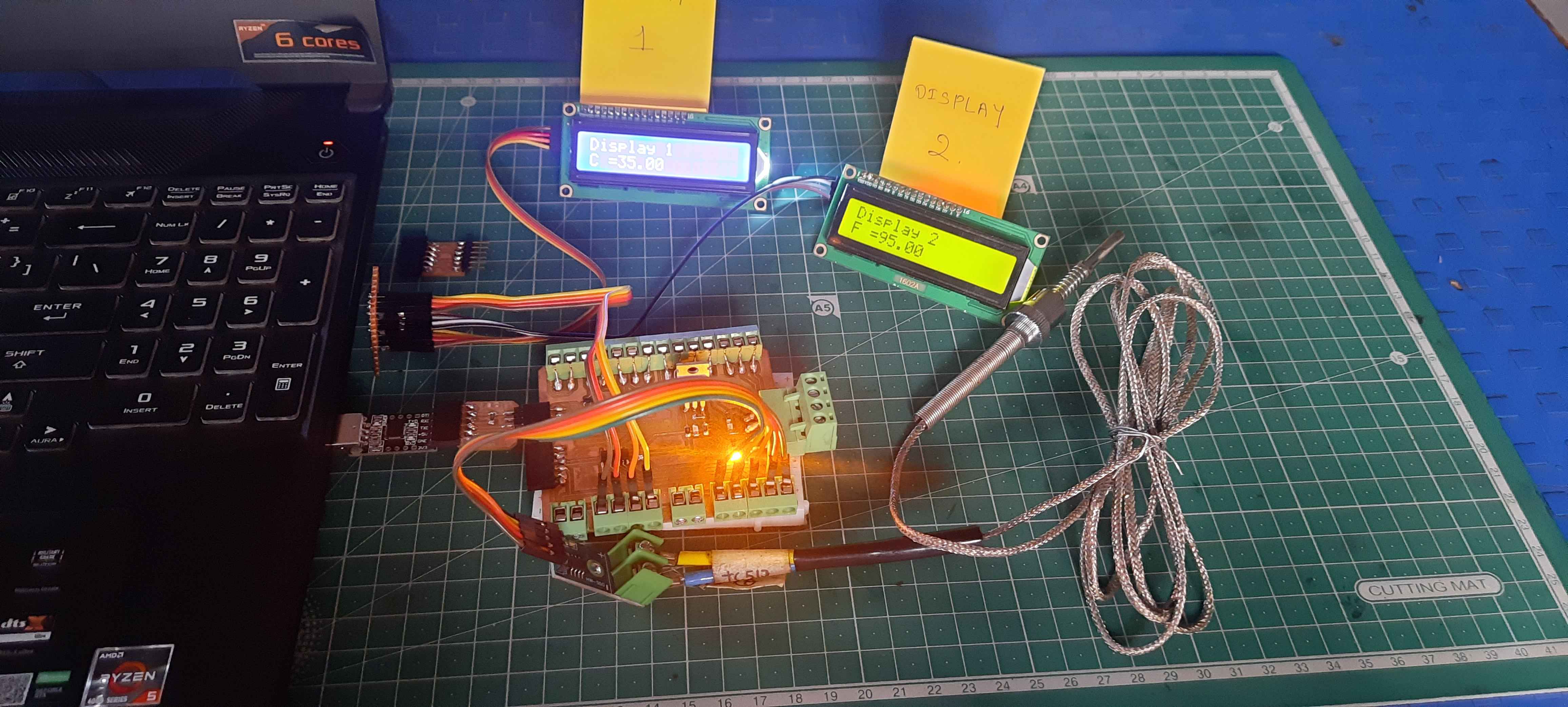
Output.