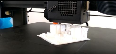
COMPLEMENTING THE DESIGN TESTS
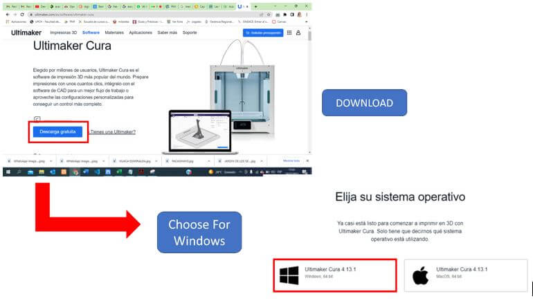
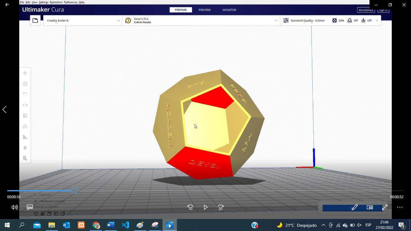
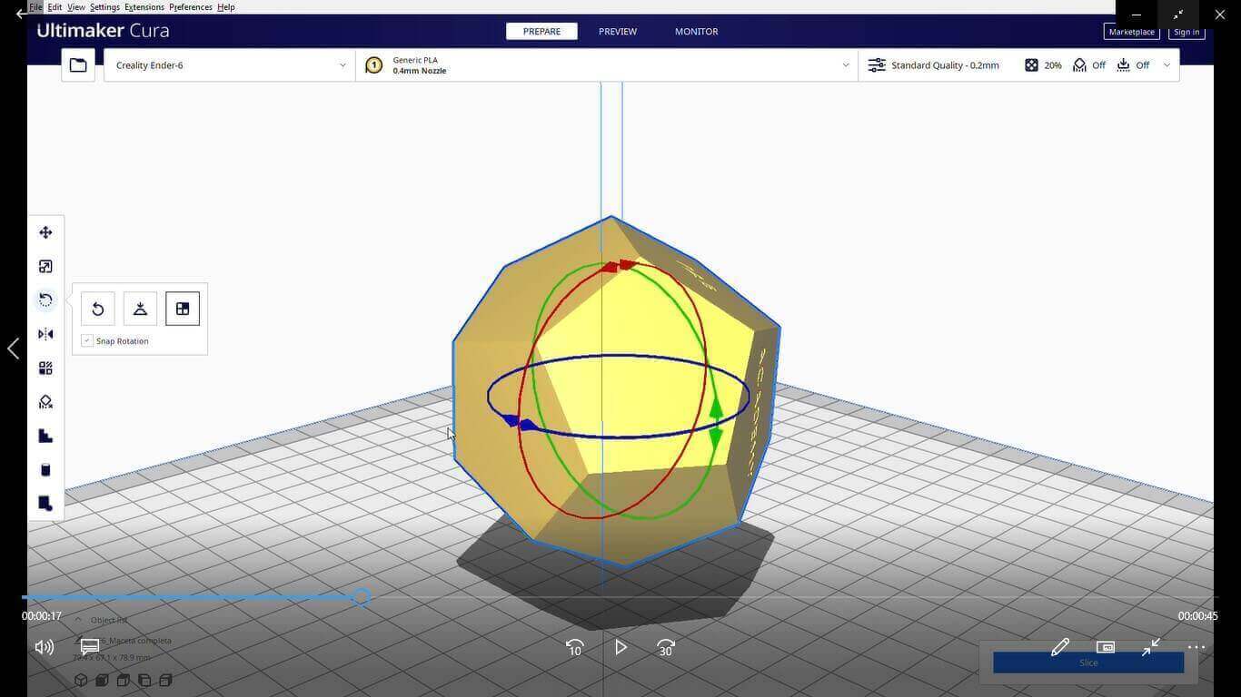
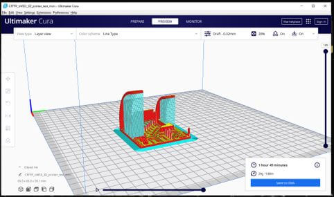
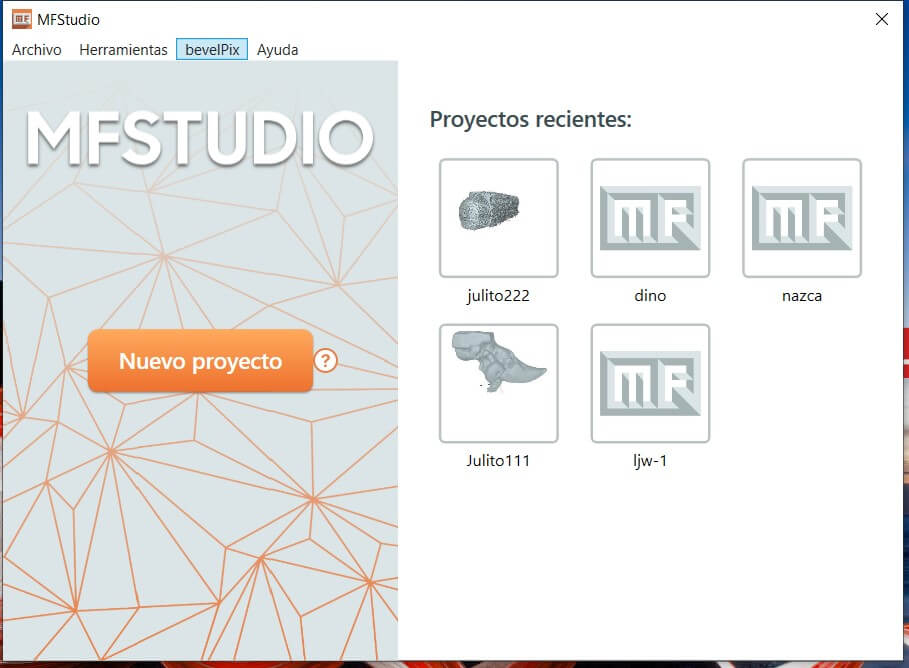
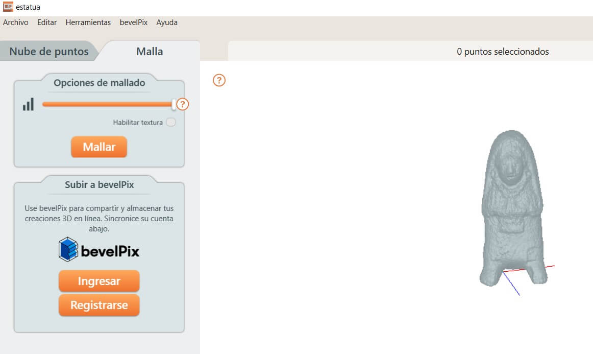
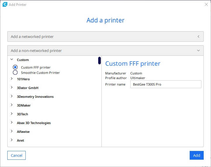
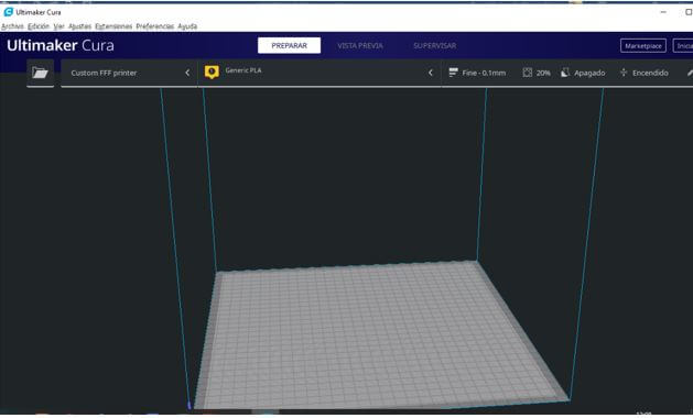
We open the image to work with in Ultimaker CURA, which is a
program that allows us to do slicing (convert a 3D object to a printable object
by transforming it into layers, that is, in GCODE code). When entering CURA for
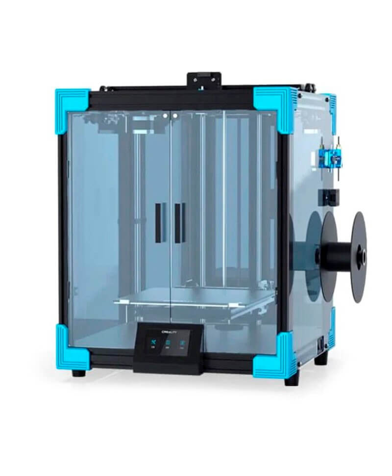
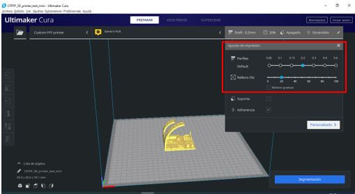
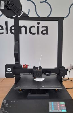
the first time, it asks us to choose a printer. In our case, it is the 3D
BESTGEE T300S PRO, but since we entered it for the first time, we chose the
CUSTOM option.
We open the image to work with in Ultimaker CURA, which is a
program that allows us to do slicing (convert a 3D object to a printable object
by transforming it into layers, that is, in GCODE code). When entering CURA for
the first time, it asks us to choose a printer. In our case, it is the 3D
BESTGEE T300S PRO, but since we entered it for the first time, we chose the
CUSTOM option.
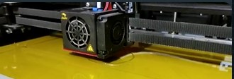
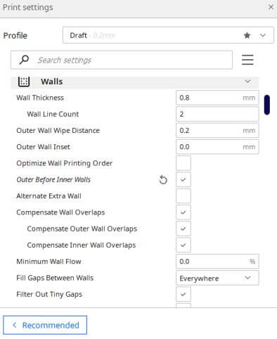
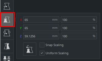
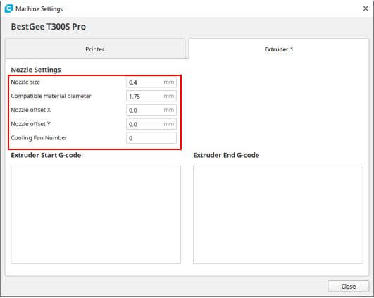
We configure the extruder with the following values where
the first value corresponds to the size of the nozzle and the second the
diameter of the material to be used (PLA) that we can find in the printer
specifications:
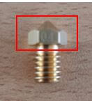
The same mouthpiece also tells you the size:
The same mouthpiece also tells you the size:
NOTE: The Ultimaker Cura software allows you to later add
another printer via the menu SETTINGS - PRINTER - ADD PRINTER.
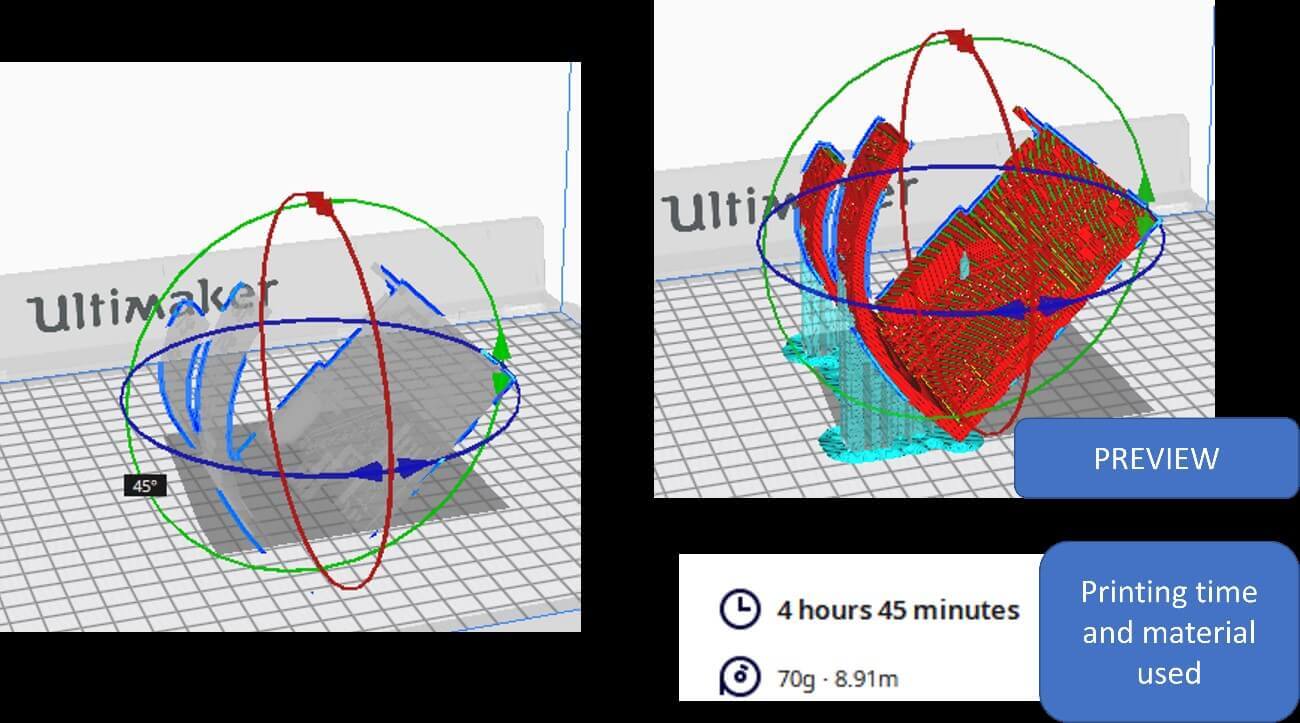
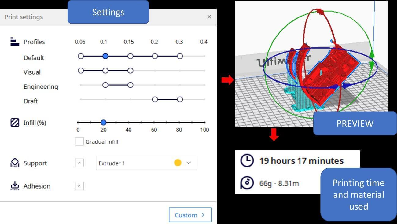
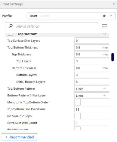
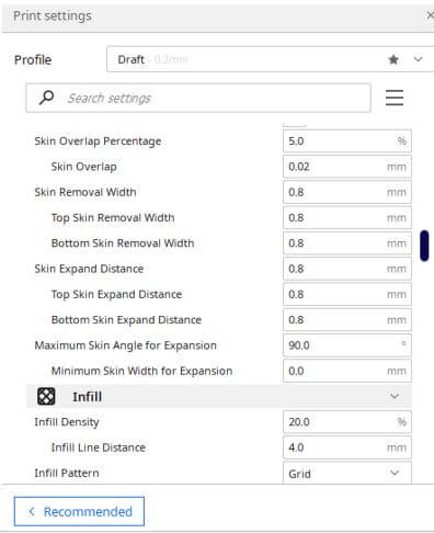
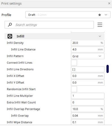
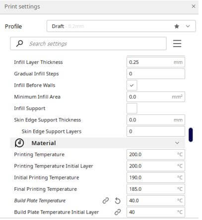
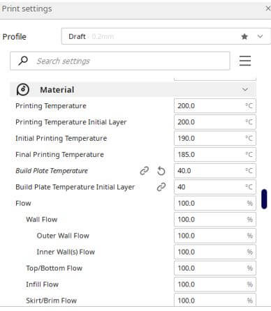
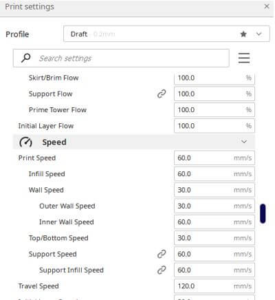
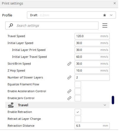
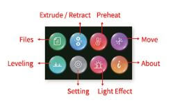
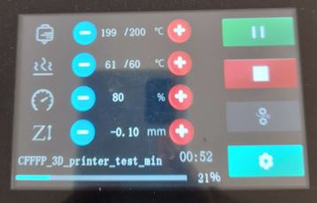
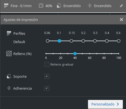
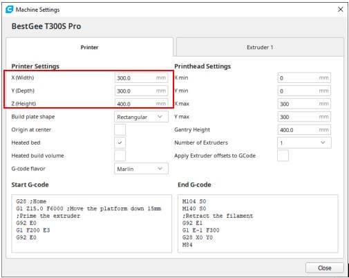
Before printing we must set all the printer values:
 t
t