Computer Design Aided
2D MODELING
Logo Design
To design my logo I used INKSCAPE which is a free and open source vector graphics editor. Install and run Inkscape and I open a new document in inkscape.

To design my logo I used INKSCAPE which is a free and open source vector graphics editor. Install and run Inkscape and I open a new document in inkscape.
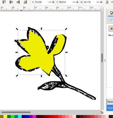
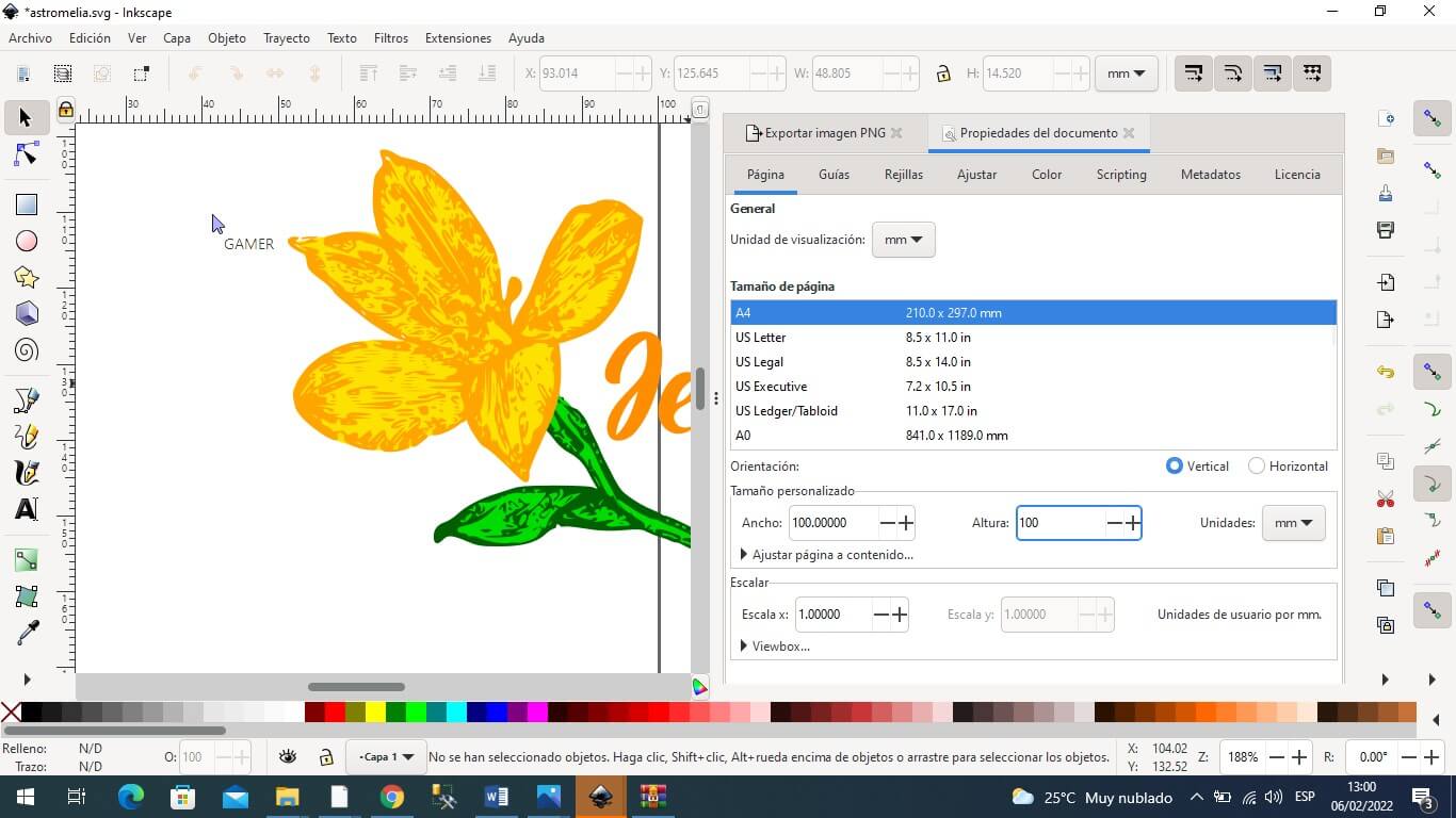
After having vectorized it, I delete the original image and select the vectorized image where you can see the nodes that compose it. I start to erase the nodes to be left with only the flower petals.

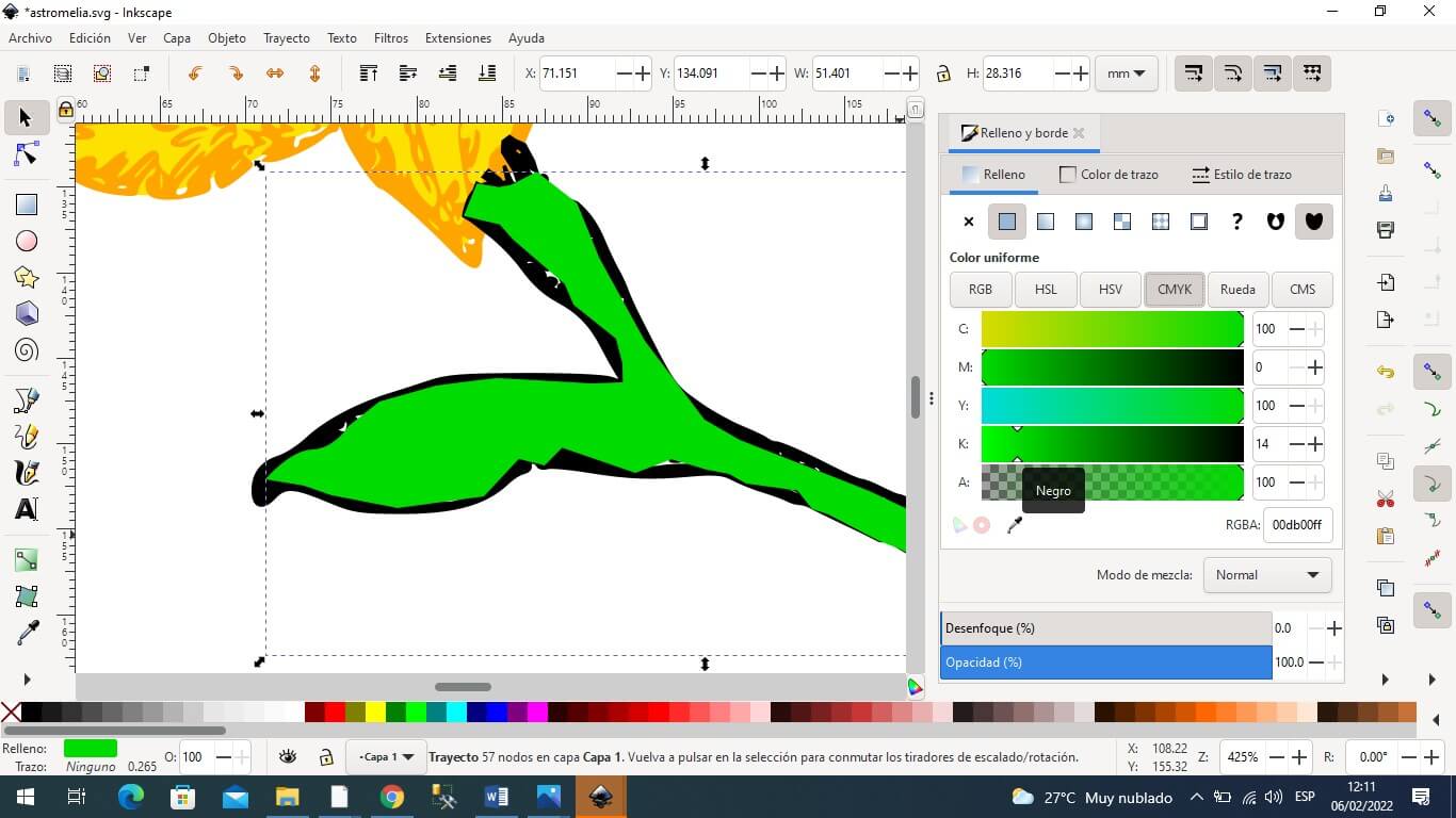
I draw an area using the Bezier tool and give it a green fill color and then send it to the background.
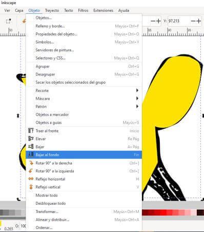
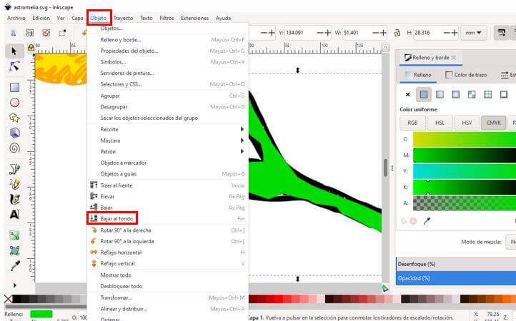
I use from the object menu the command lower to the bottom and thus the stem can have a fill color.
To download typography enter the following address:
https://www.dafont.com/es/theme.php?cat=601&text=JewNel
and then click install.
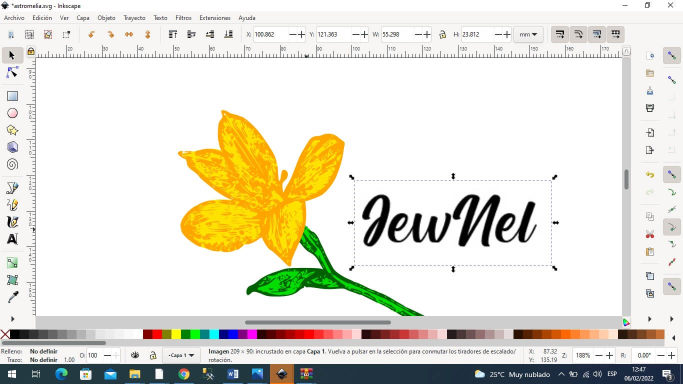

I also vectorized the text and gave it a fill color and remove the border color.

Finally the image I group it and export it as PNG.

I have used COREL DRAW as a design program and here you can download my worked files. Download here.
Some photos that show the process carried out can be viewed here.
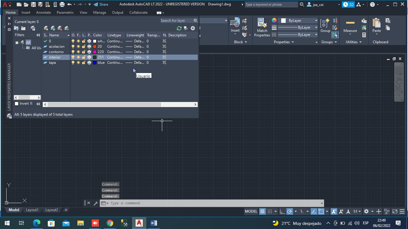
To model the jewelry box in 2D use Autocad. Create layers to work with the lid, interior, outline, and more. I create layers with LAYER PROPERTIES giving them a name and a color.
We are going to save the file in Autocad 2D.

I have used AUTOCAD as a computer aided design program to model in 2D the jewelry box to be made. Here you can download the worked file (diseño_de_cofre.dwg and diseño_de_cofre.bak).
I save the file as jeweler-main.
Check units in centimeters
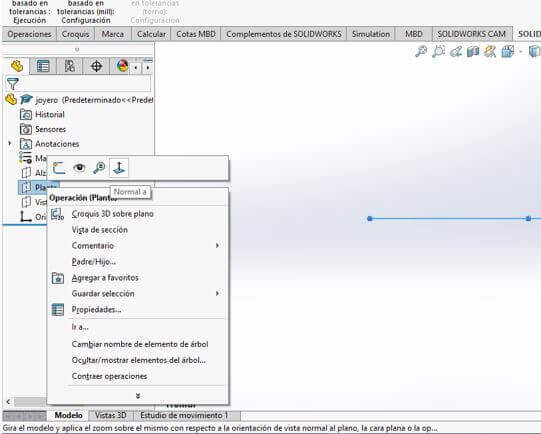
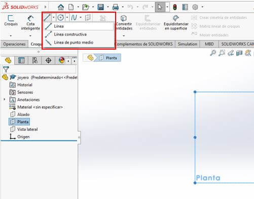
I right click on plant to choose NORMAL A to work on the front side.
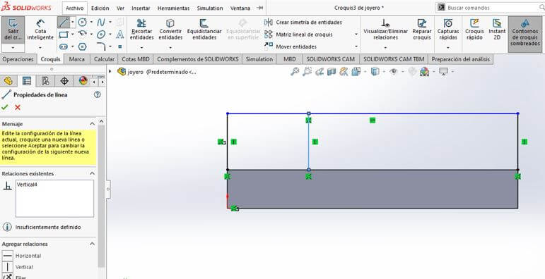
I choose the line command in the sketch tab.
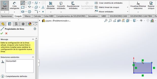
Draw a rectangle by clicking inside the indicated area not taking the measurements into account yet.
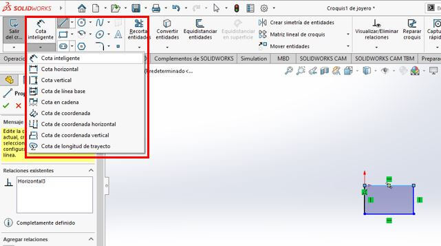
I click on smart dimension to give them the necessary measurements.
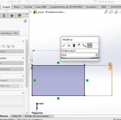
I select the line and move to the left and then release the line and a window appears where I indicate 15 cm as the measurement. Then I click on the green check.

Then I select the upper line and apply the previous procedure and give it the measurement of 20 cms.
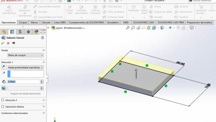
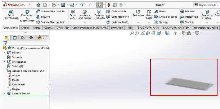
To build upwards, I first build the 2 cm area by choosing the extrude boss/base command from the operations tab.


Here we have the lid of the jewelry box in acrylic material
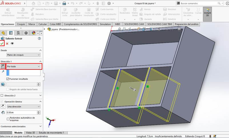
Finally we have the piece that goes inside the jewelry box

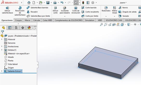
I have used SOLIDWORKS as a computer-aided design program to
model the jewelry box to be made in 3D. Here you can download the worked file (joyero_PIEZA.SLDPRT , joyero_principal.SLDPRT and
joyero_TAPA.SLDPRT).
To perform 3D animation in Solidwors, an exploded view of the designed object is created; then enter the Motion Study tab and use the animation assistant to indicate the corresponding animation. The following series of animations was chosen: rotate – explode – collapse – rotate, as shown in the following video:
Jeweler's assembly
Here you can see a video of how the procedure is performed and finally the video that is generated from the simulation. Click here.
created with
HTML Designer .