4) PCB fabrication workshop
Using the PCB pictures from this reference to create process file .rmlUsed Files
| Files | Link |
|---|---|
| Traces | Download |
| Outline | Download |
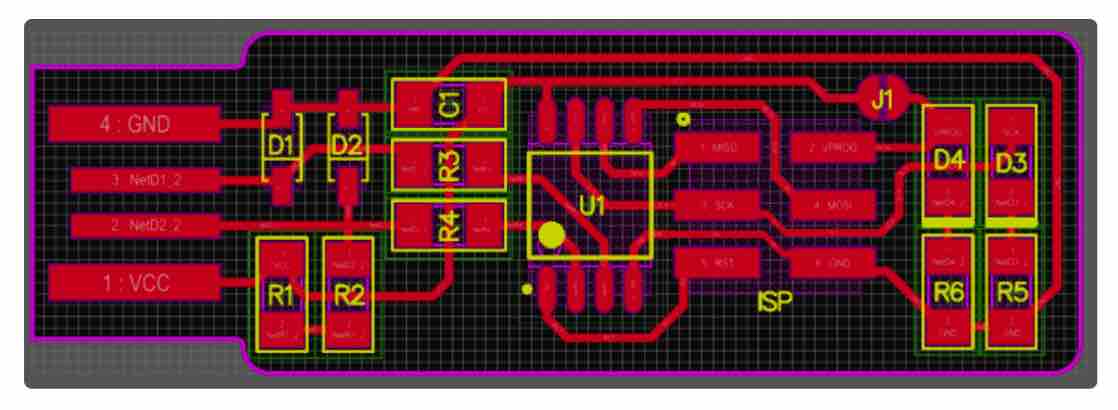
4.1) PCB Design and preparing
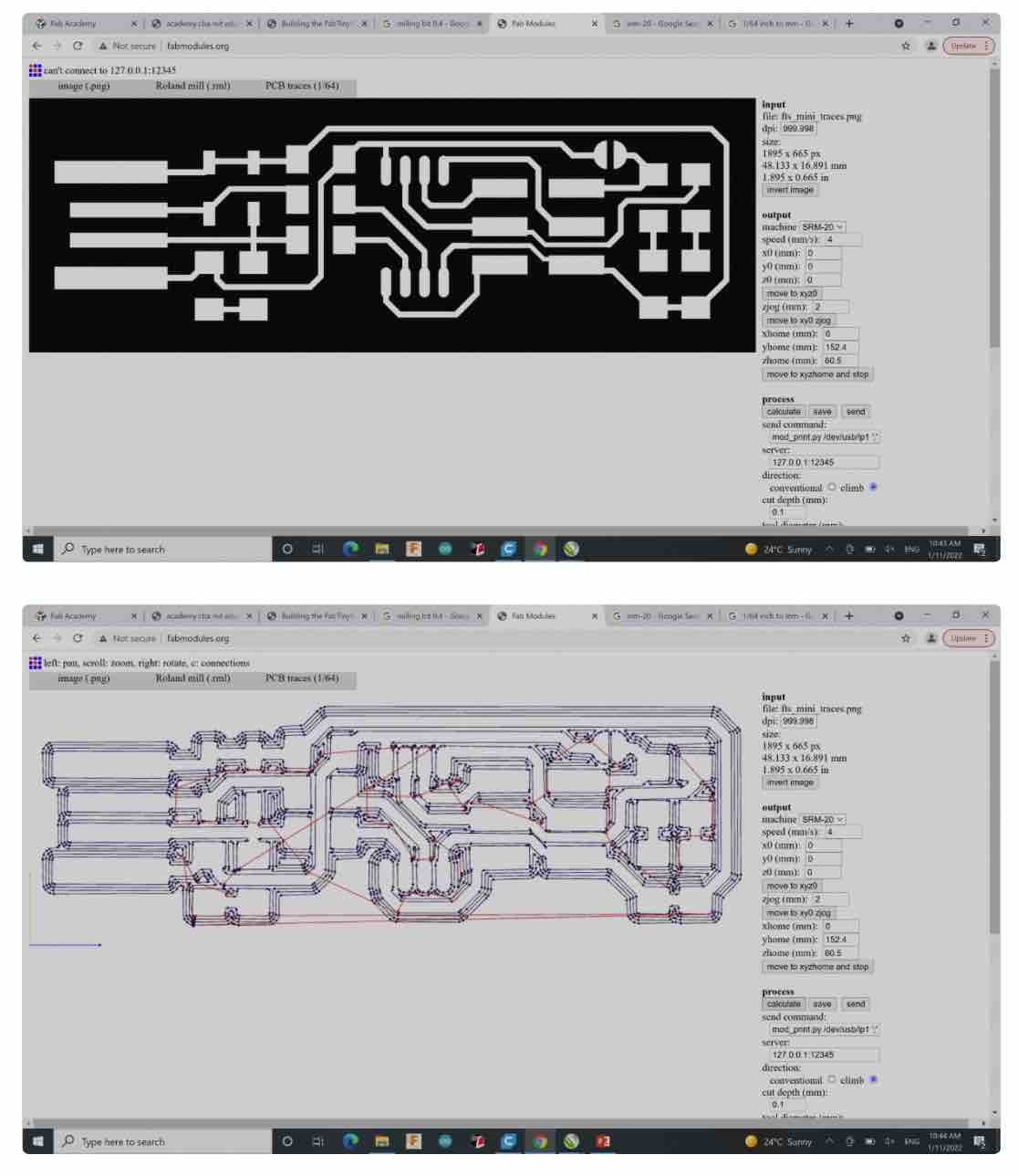
Using the Fabmodules to convert image to G-code for the milling process.Steps:
**Traces**
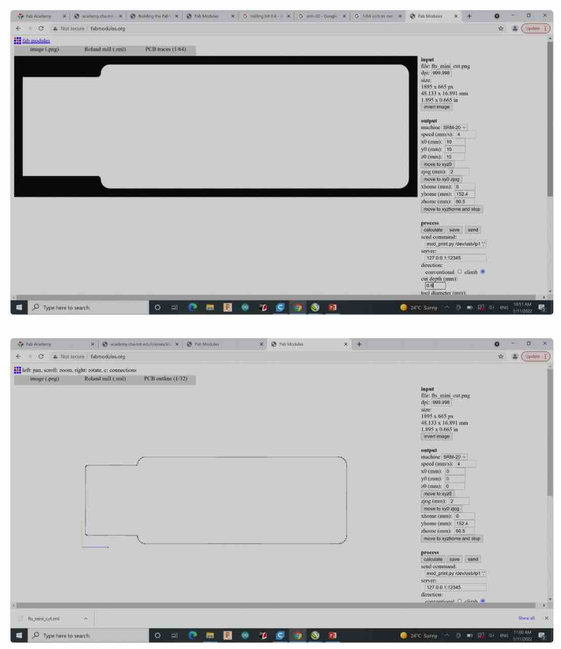
**Outline**
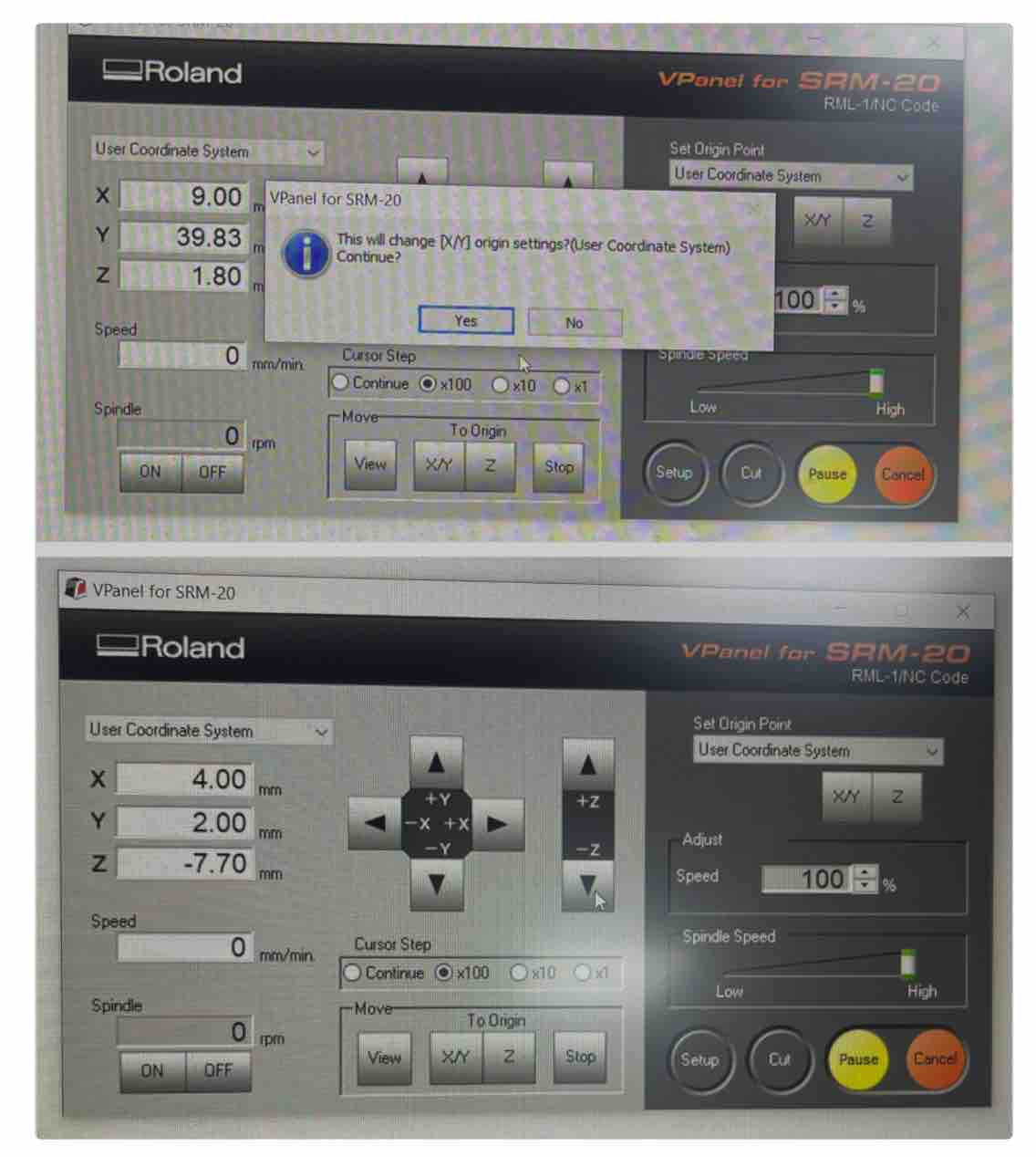
4.2) PCB fabrication
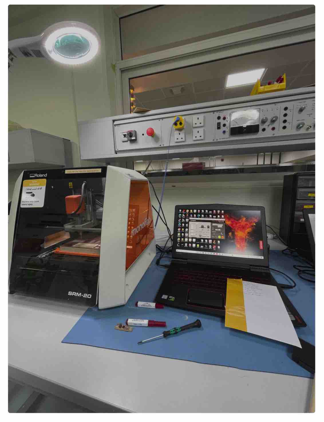
Used machine: monoFabUsed software: VPanel
Process: Milling
Mill bit used: 1/64 for traces; 1/32 for outline
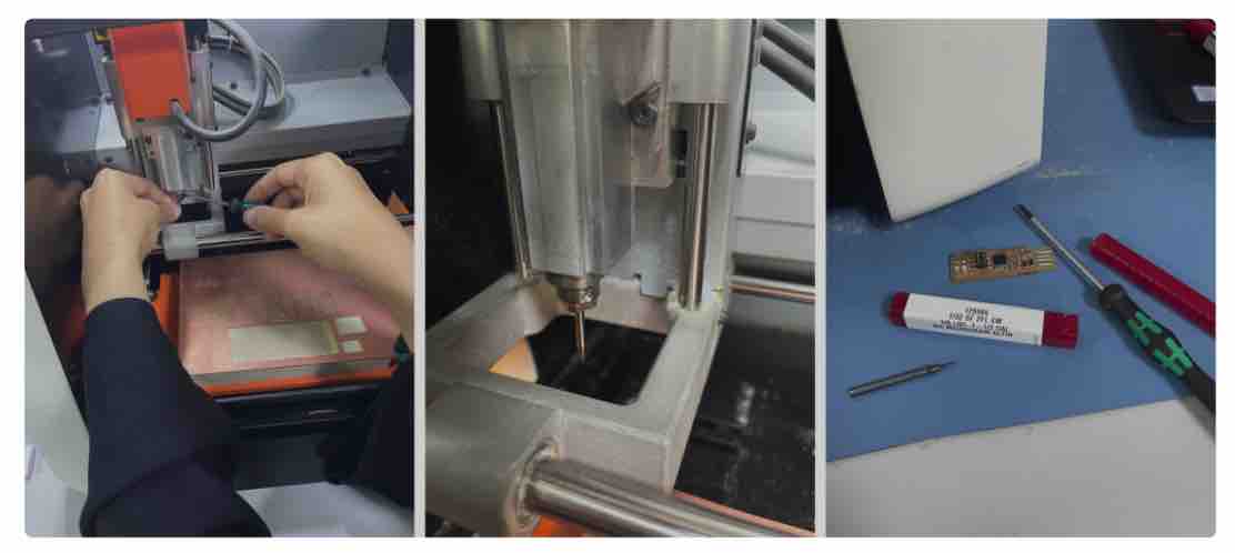
**Workplace**
**Setup - Leveling**
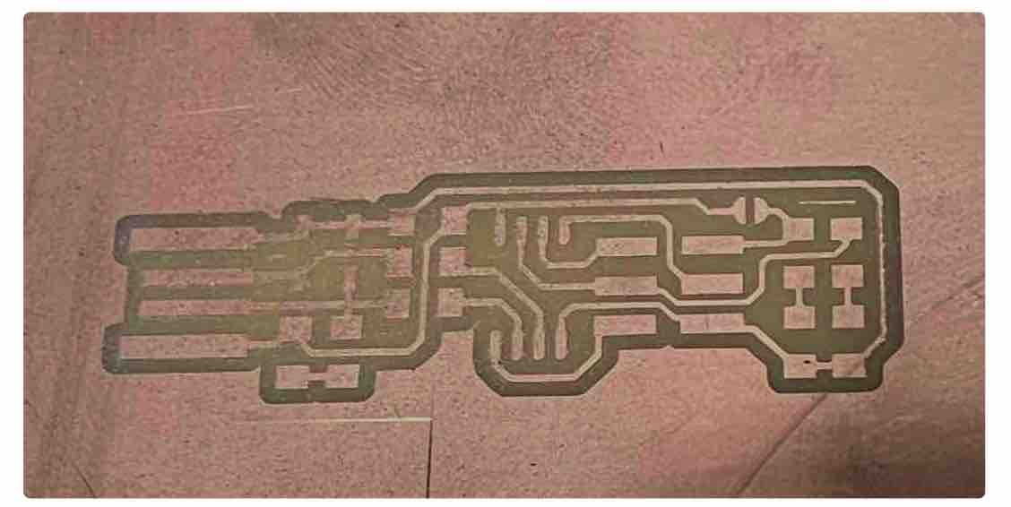
**Milled PCB traces**
**Attach and Replace Mill bit**
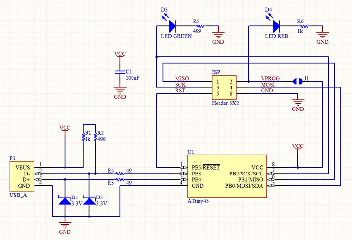
4.3) PCB Assembly
**Components**
2x 1kΩ resistors
2x 499Ω resistors
2x 49Ω resistors
2x 3.3v zener diodes
1x red LED
1x green LED
1x 100nF capacitor
1x 2x3 pin header
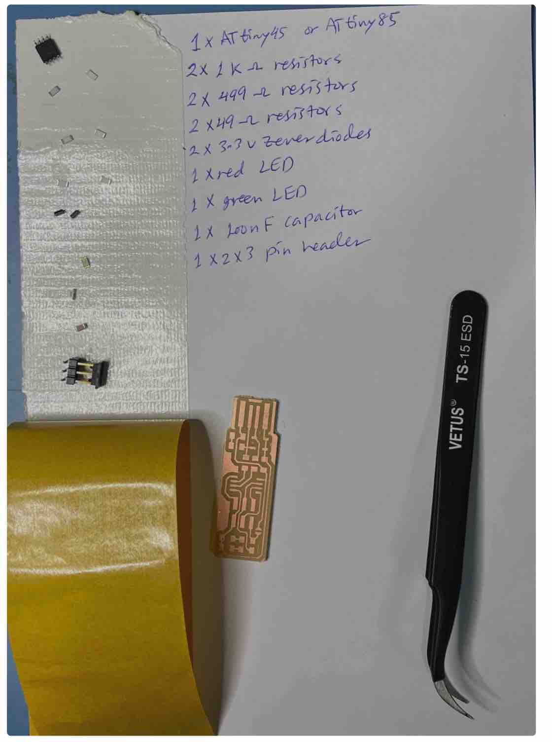
**Soldering area**
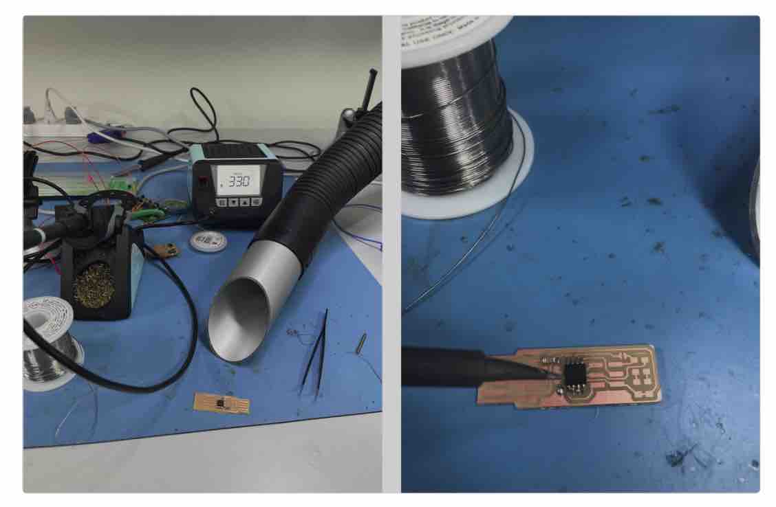
**PCB board**
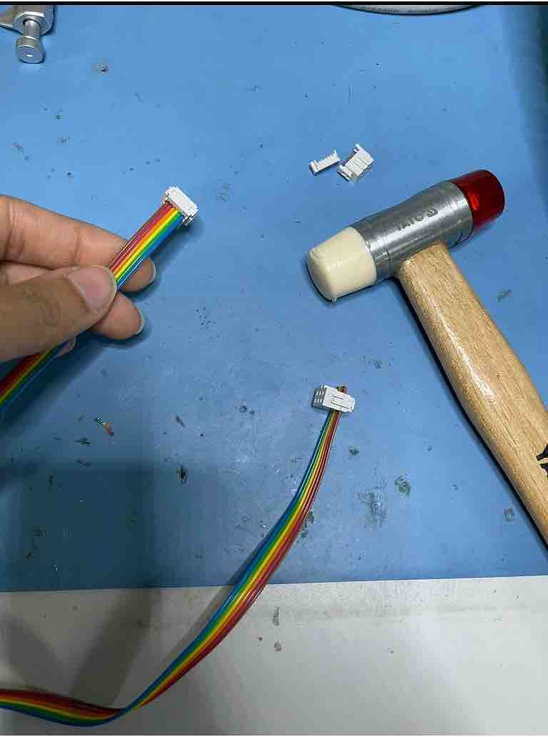
Update 21/01/2022:
Ribbon wire:
Update 06/02/2022
Programming:
Steps:
1) Open terminal and past the following command to install Homebrew:
ruby -e "$(curl -fsSL https://raw.githubusercontent.com/Homebrew/install/master/install)" 2) Install avr-gcc toolchain
brew tap osx-cross/avr brew install avr-libc brew install avro-c brew install gcc 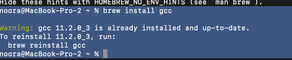
brew install binutils brew install avrdude 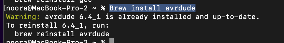 Last step is checking avr-gcc version; by typing the following command:
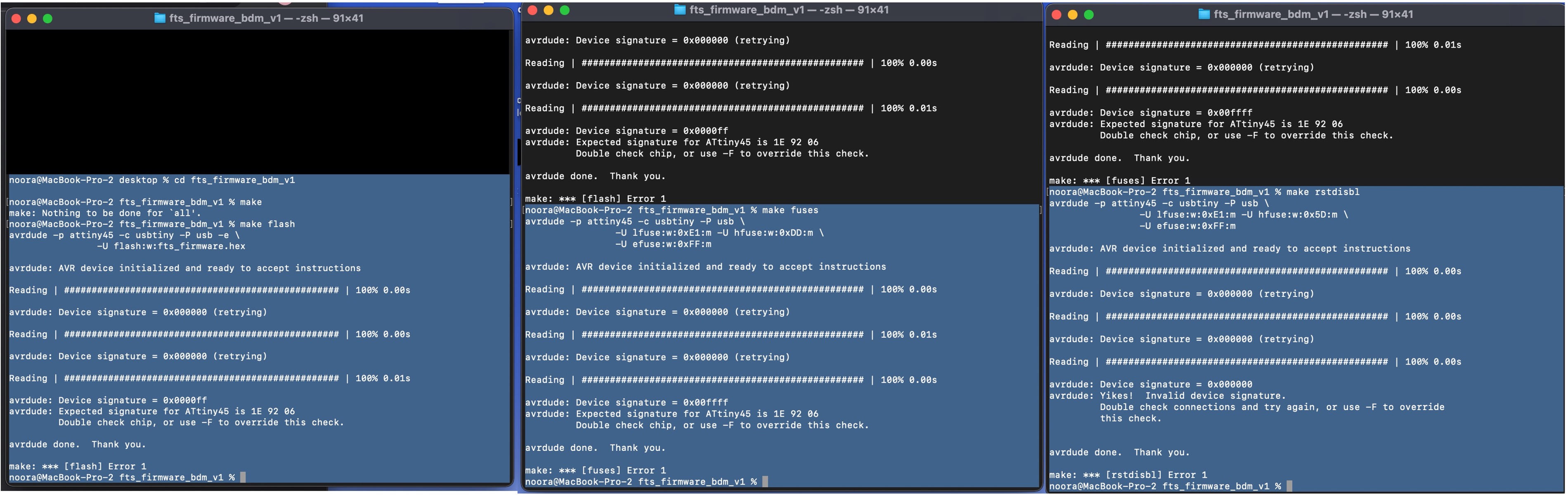
 avr-gcc –version 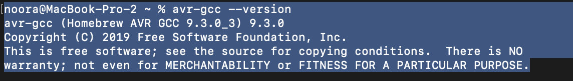 3) firmware
Using terminal to navigate the fts_firmware_bdm_v1 folder, and run
make In order to create this file (fts_firmware.hex)
4) Using USBTiny to program my PCB: