Computer controlled machining
Group Assignment
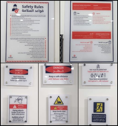
safety first: when you deal with any machine in the lab make sure that you take the safety instruction in considering especially the CNC machine because it's a large scale machine and any mistake could make large damage.
CNC setup
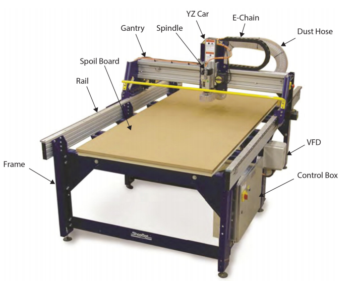
in TechWorks we use ShopBot PRSalpha ATC 96-60-8 this CNC has 2440mm x 1220mm bed size and has a rapid transit speed of 1800 inches per minute and cutting speeds of up to 600 inches per minute.
Tooling Details:
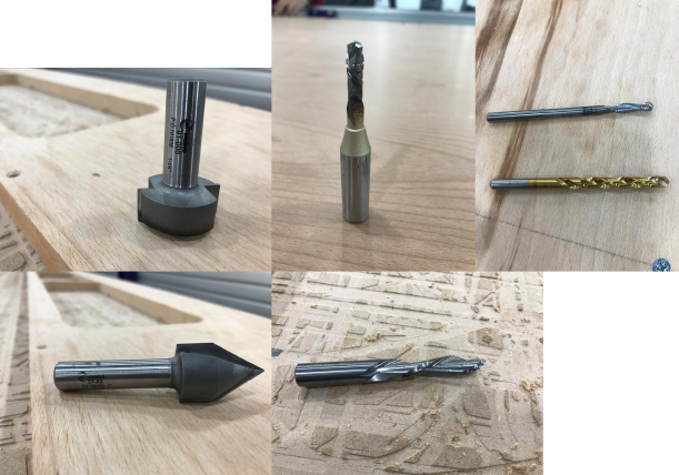
this week we learn about Carbide Tipped - Spoilboard Surfacing, V-Carve, End Mills, etc. Each has been designed for a specific purpose and all can be used in a CNC router but I will talk more about v-carve and end mill in details because I make my assignment using this tools
- 91-000 Carbide Tipped - Spoilboard Surfacing
- Solid Carbide router, 2 flute, downcut
- 60-100PLR Solid Carbide - Polaris Compression
- Carbide Tipped router, 2 flute, V Bottom
- Solid Carbide drill, 2 flute, 8 facet
individual assignment
Design
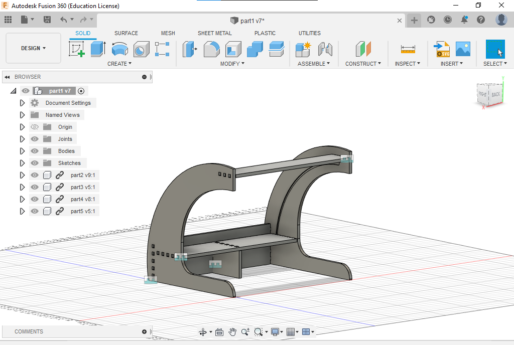
this week the assignment was to make something big using a CNC machine, so I decided to make something useful too, my project was soldering both that contain led strips to make SMD components soldering easier .
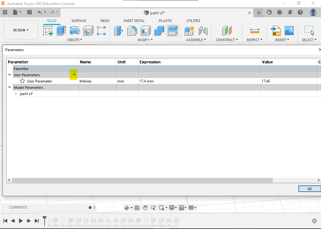
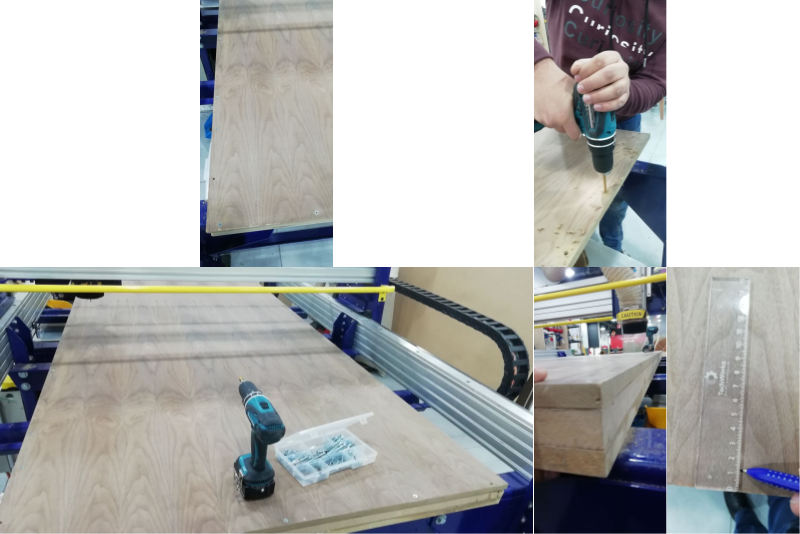
before started designing the measure the board thickness was 17.4mm it was a super important step to take the thickness into consideration when I design because the design was based on press-fit joint .
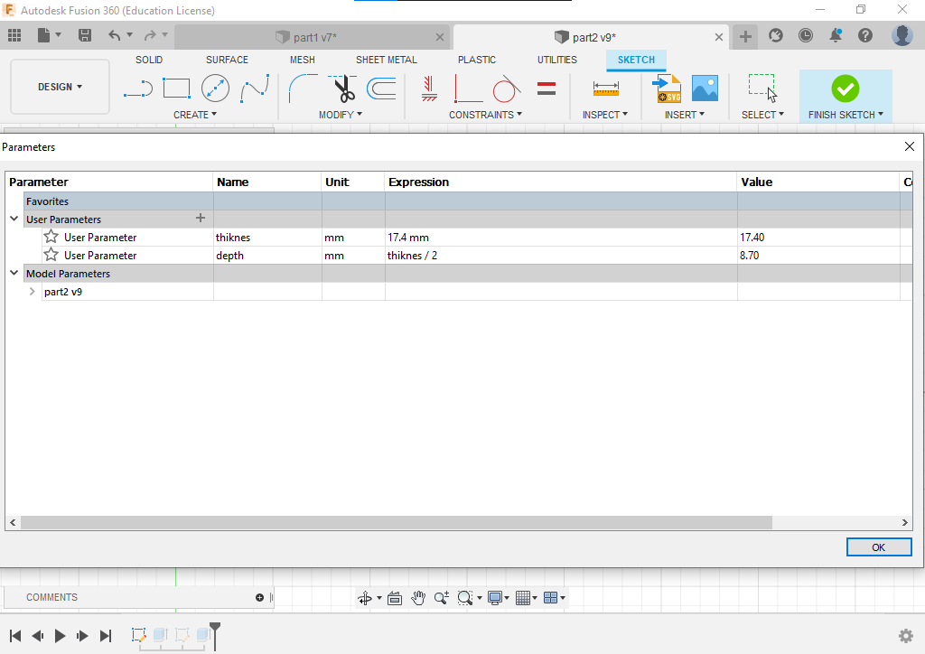
another important rule when you make the design be fabricated using CNC is to make the design parametric to change the joint dimensions if the material thickness was changed, so I start with material thickness and set the thickness parameter to 17.4mm .
now I start my design with a 2D sketch
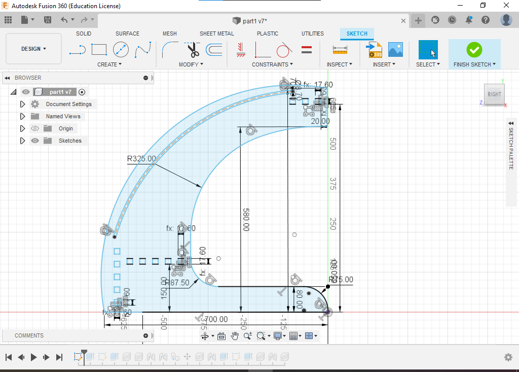
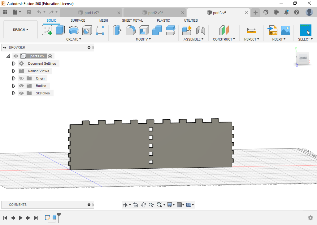
then extrude it
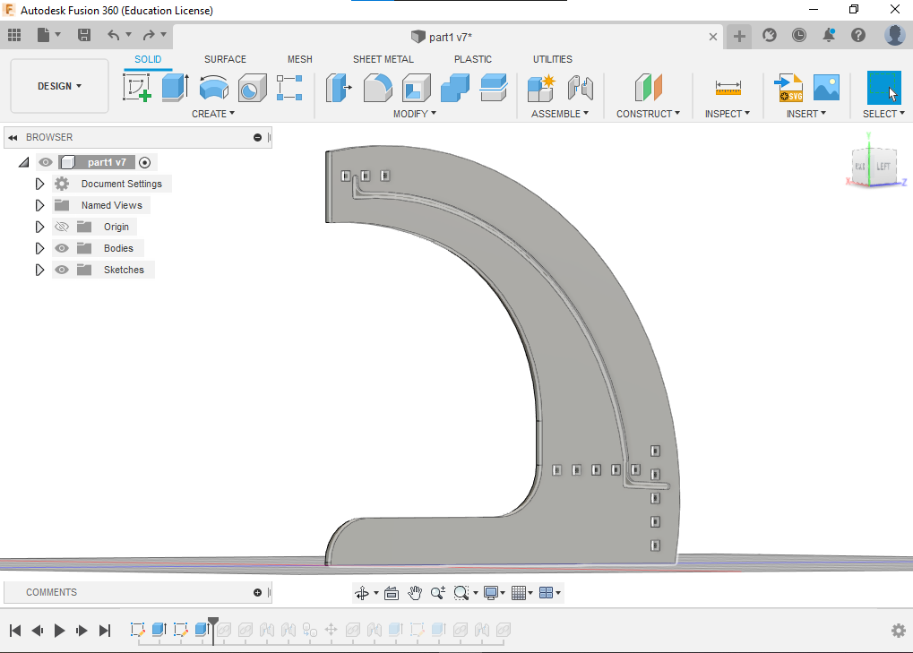
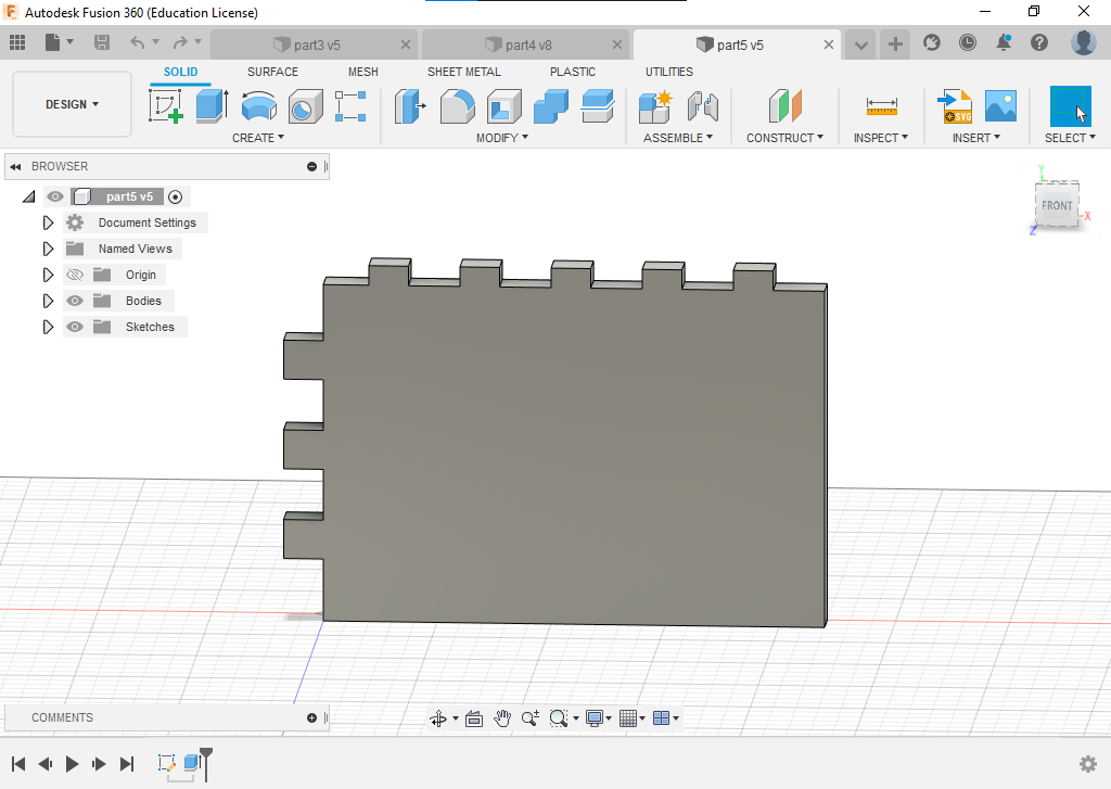
then I design the second part and set the fingers dimension to be half the board thickness just to make it better look and the female part will be cut as bucket not through for better look as I mentioned.
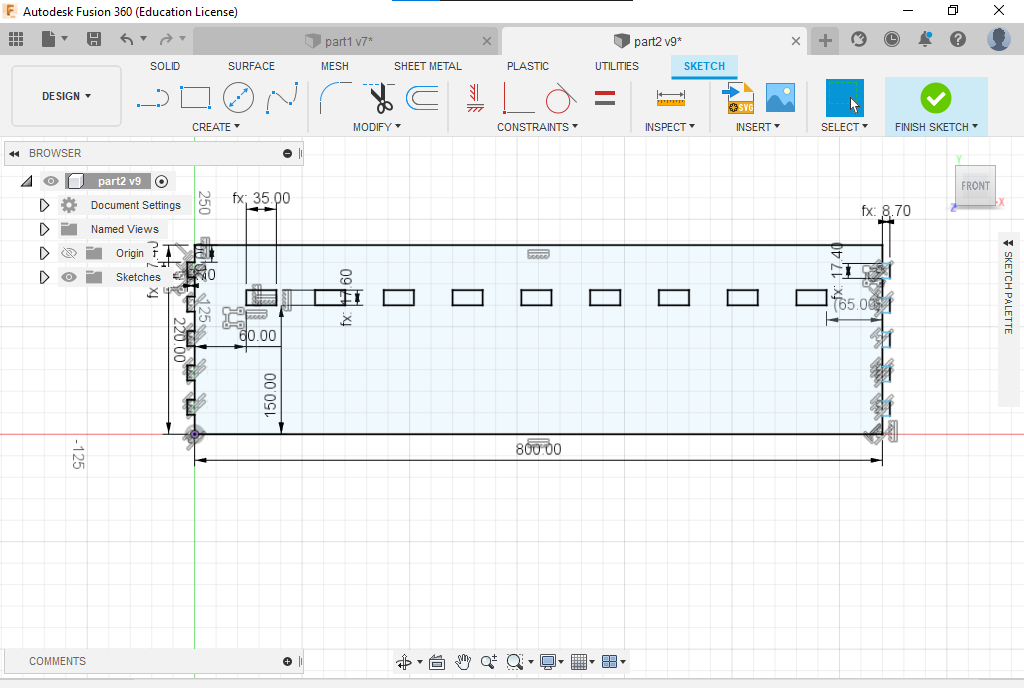
to hold the LED strip I make a slot with 11mm width and depth of 5mm because the LED strip dimension is 10mm width and 2.5 mm depth.
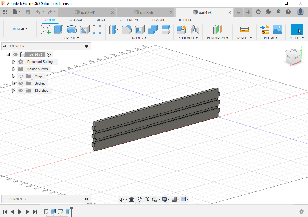
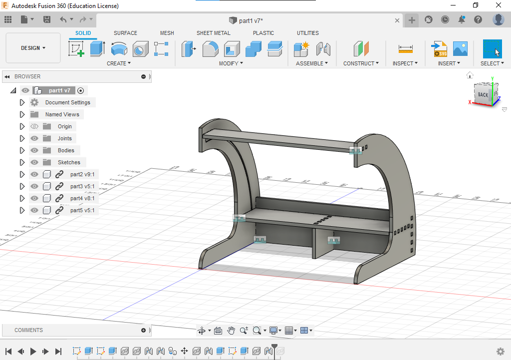
now every thing is ready to assembly
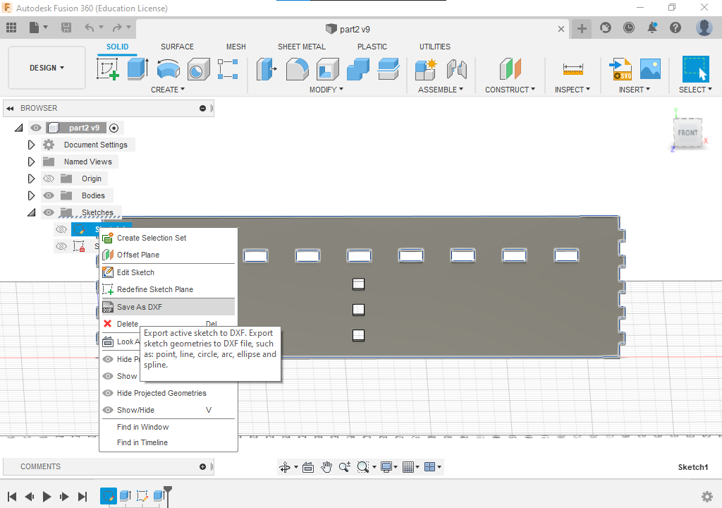
now before going to v carve we have to export each part as DXF file which will be accepted as a 2D design with the same dimensions in design .
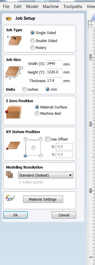
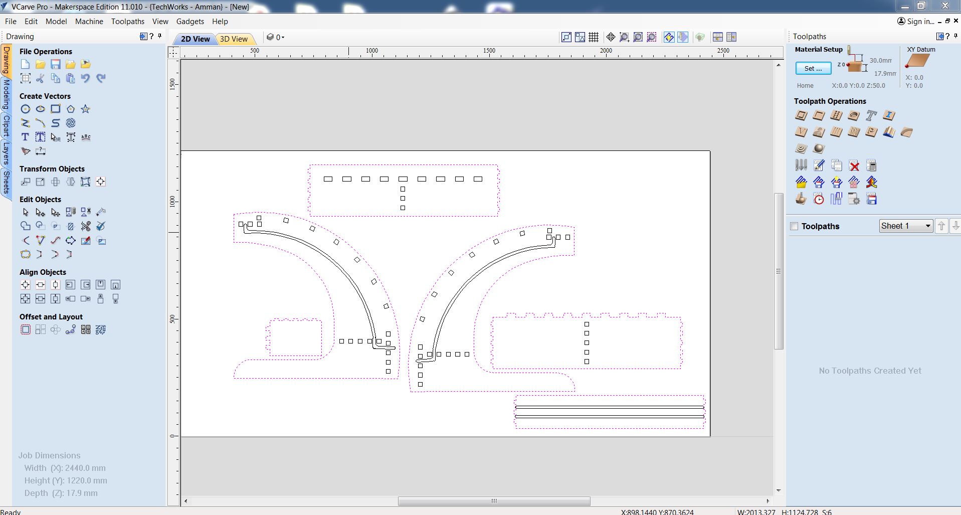
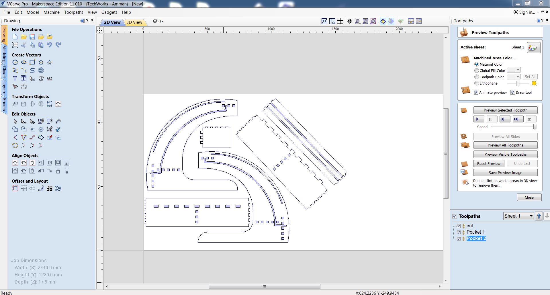
It's time to go to v carve , if look at the photo down below you will see the main screen for the v carve .
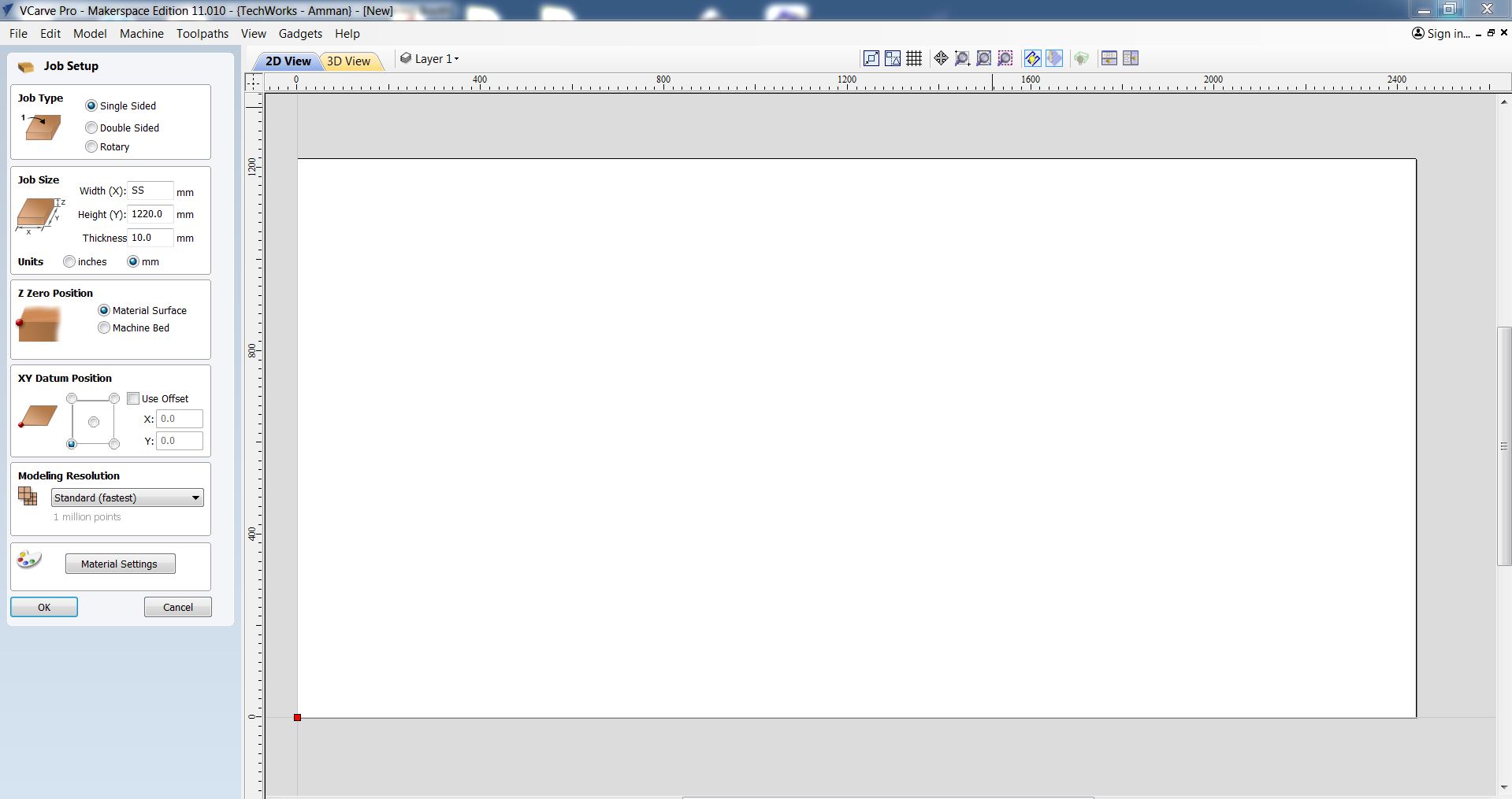
here you can set up your job in my case I use a one-sided board with dimensions of 2440mm *1220mm with 17.4mm of thickness but I add a 0.5 mm just to make sure that the cut will be done perfectly, after that you have to set the Z-axis zero point by material surface or machine bed I choose the material surface because it's easier to celebrate on the smooth surface rather than machine surface which is full of holes and cuts.
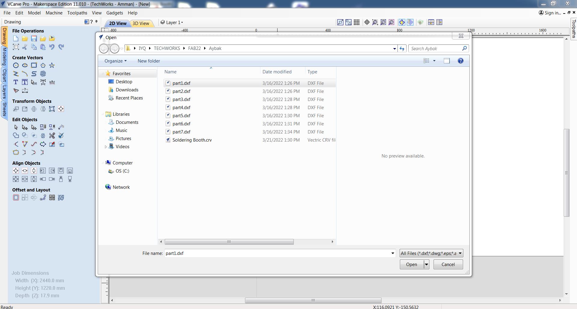
after pressing ok, it's time to import our DXF files, go to file>>import>> import vector, then select DXF files that we have already prepared one by one .
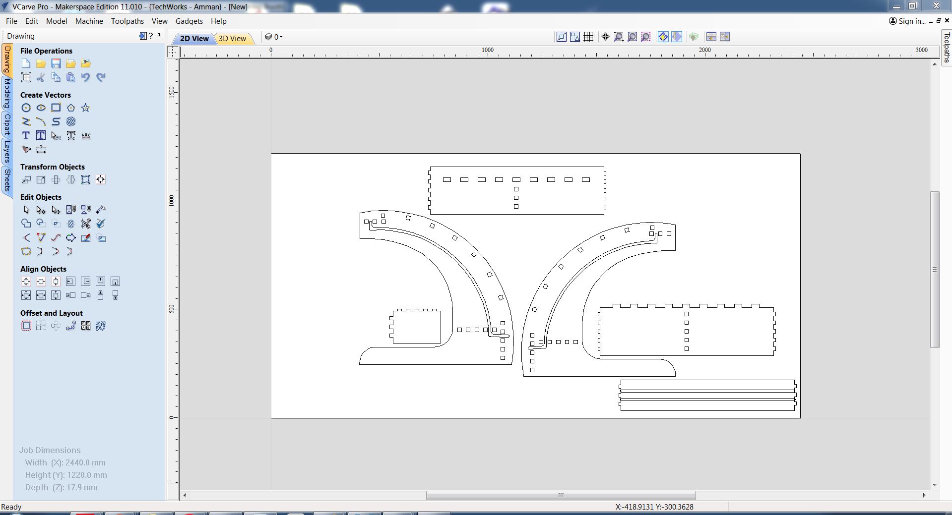
now let's set up the machine toolpath, press on toolpath ons the right top of the screen then select the parts that you want to cut, I want to begin with cutting parts so I select the outline by holding the Shift key then select all the outlines, after that press on 2D profile toolpath .
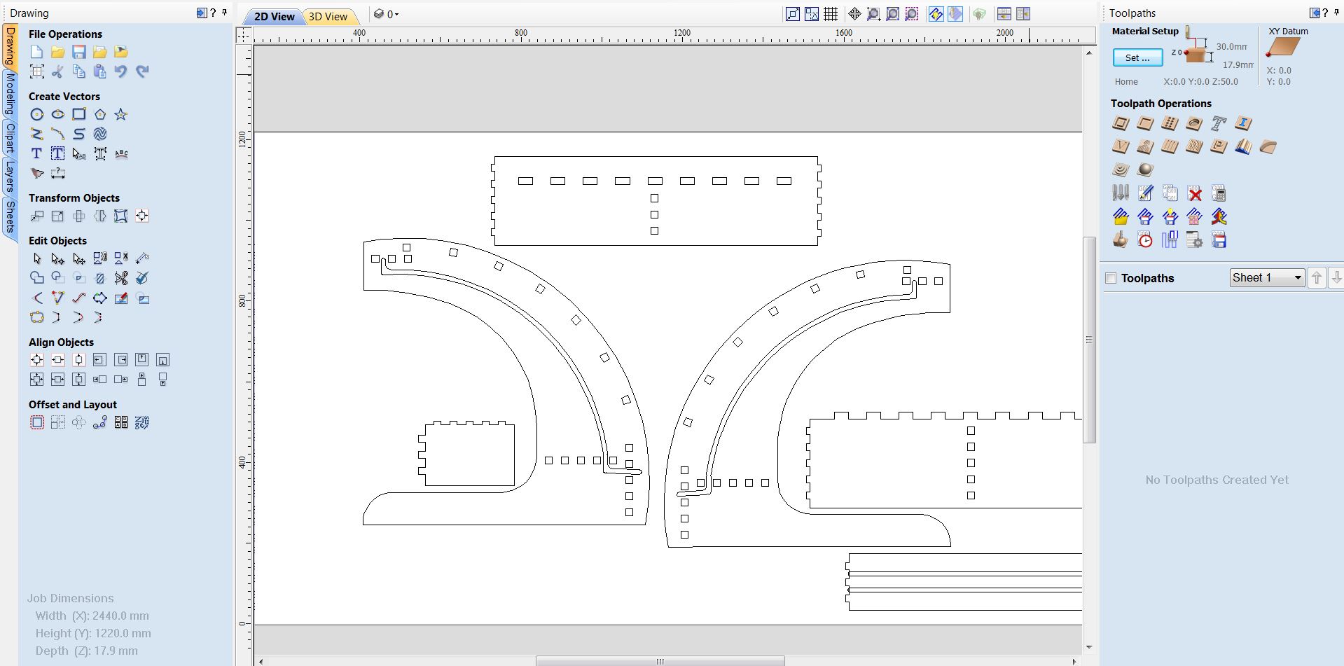
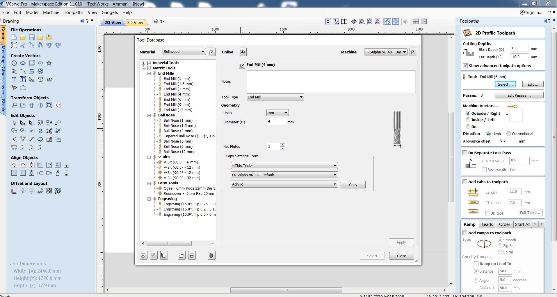
set the starting depth to 0mm and the cutting depth to 17.9mm then select the tool, here we select Endmill with 4mm tool diameter and two flutes then click apply .
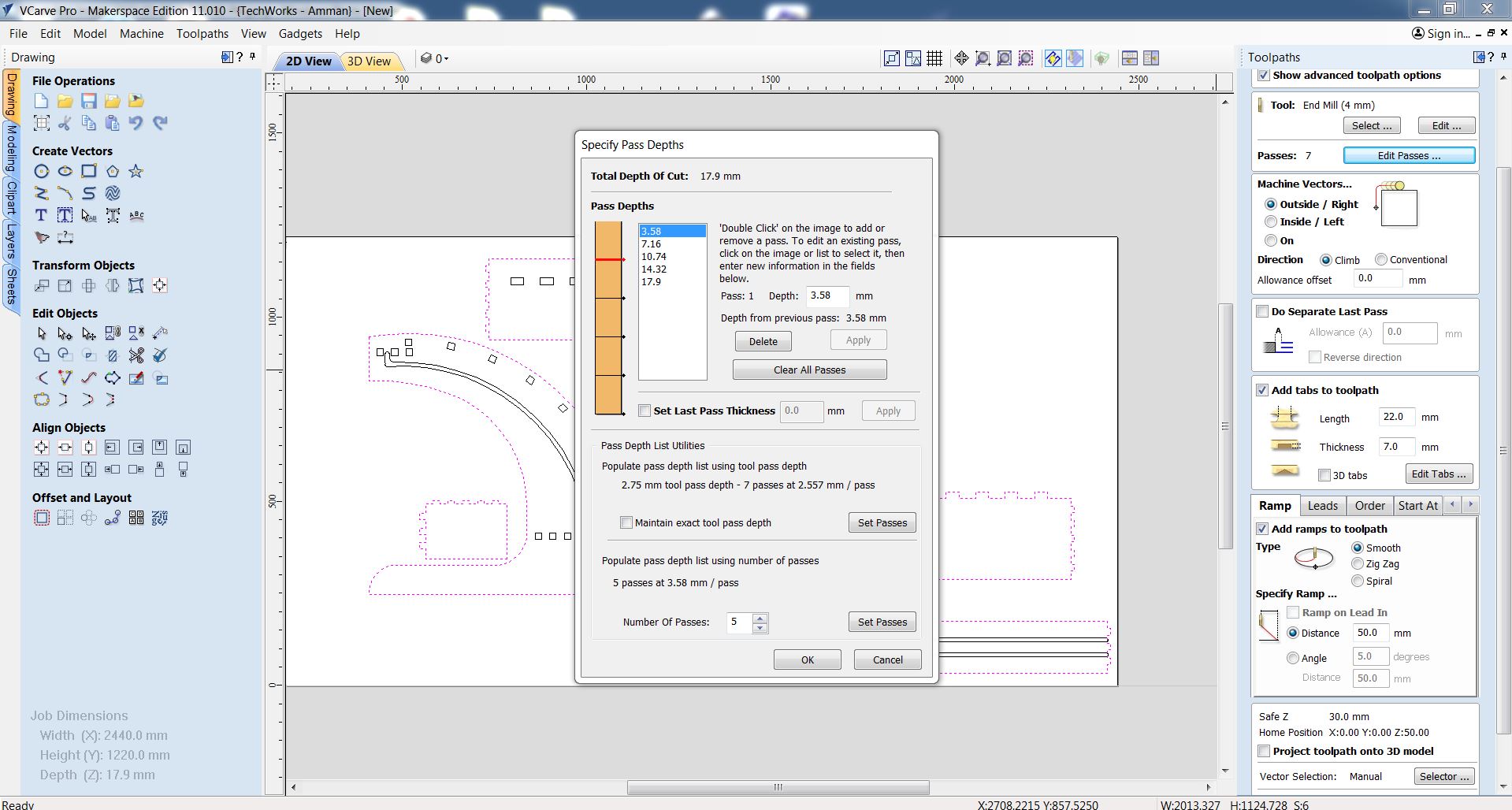
after that, we can edit the number of passes, here is a simple equation if you decrease the number of passes you will decrease the time but you will add more load on the spindle and on the tool, and because by decreasing the number of passes you will increase the depth of cut each time, but if you do the opposite thing you will increase the time and decrease the load, so you have to make a balance between these two options. here I select 5 passes with 3.58mm for each of them and after testing its work perfectly .
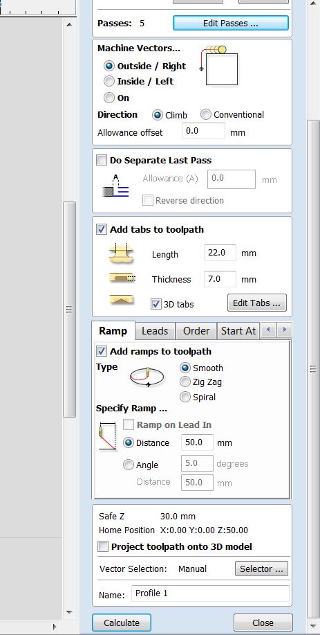
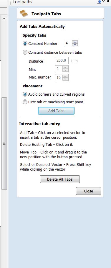
In “Machine Vectors” menu, choose “On”. check the "add taps to toolpath" then check the 3D tap box that will be easier for the machine to make taps rather than rectangular taps. For direction click “Conventional”. Enable “Ramp Plunge Moves” and set direction to 50.0mm. This will make endmill plunge gradually in X or Y direction. Rename the toolpath to “cut”. Shift and select engraving paths and click “Calculate”. A preview toolpaths opens where you can simulate the engraving operation. Click on “Close”.
here I select 4 taps for each part and I arranged the taps to make sure that don't effect the joints .
now let's make a pocket toolpath profile. with 8.9 depth of cut for the fingers joint we make a pocket with half of the board thickness, this will make the joints strong and have a better look. not that I use the same 4mm Endmill that we use to cut the outlines it's perfect for the pocket too .
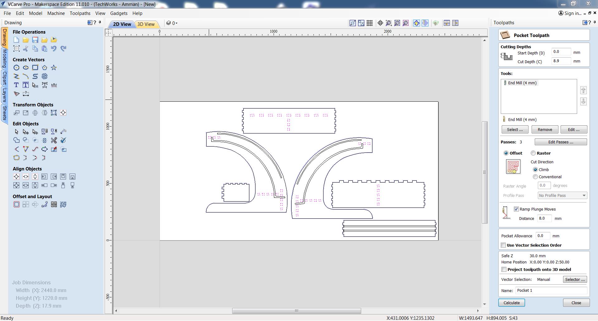
I make another pocket profile for the slots with depth of 5mm using the 4mm Endmill .
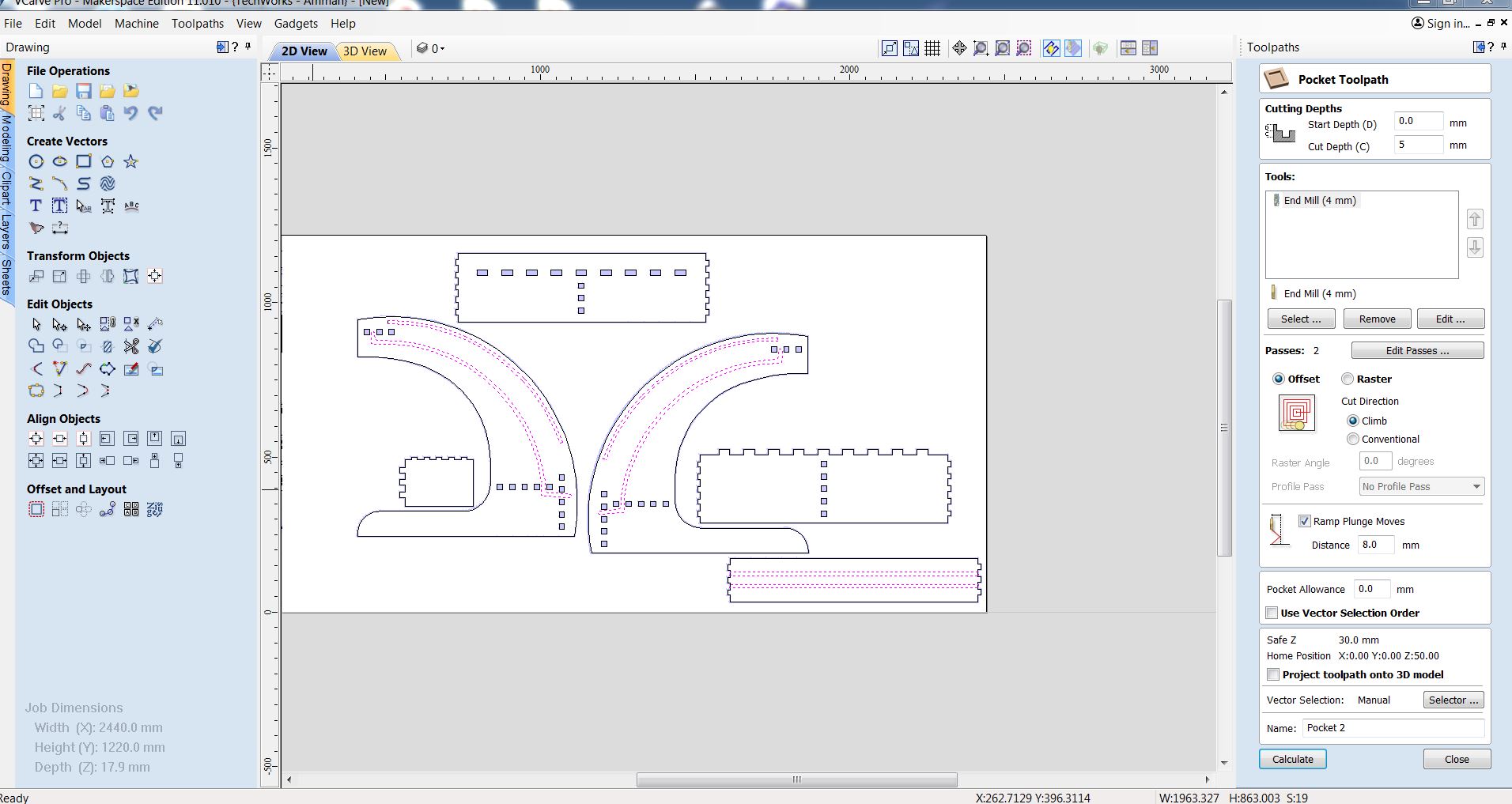
after doing the profile setting I arranged all the parts in a way that saves as much as possible of the board. and after a done form nesting process I recalculate all the profiles in the new place .
now before start cutting we have to fix the board on the bed and this step is so important because the spindle will move the board easily without board fixing. to do this we have to clean the bead then start fixing by using drill to drill the board then but screws on its blace, but you have to make sure that the screw isnt offset more than one cm form the eadge of the board so it will not break the tool .
Then i zero the 3 axis (x,y,z) and save the program in order to send it the ShopBot. to setup the machine x and y zero we have to move the machine to the edges , then we zero the 2 axis x,y whoever for the z axis we start move the axis down with small steps and in the same time shake a small sheet under the tool and when the sheet stuck under the tool that will be the zero for the z axis .

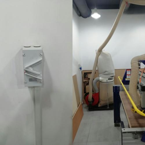
before start milling we must turn the vacuum suker on to keep the board clean while milling and to have a good finishing .
preparing the program

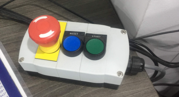
now press the green button to turn the spindle on and start the job
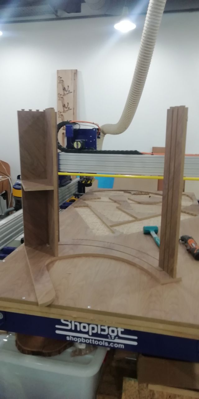
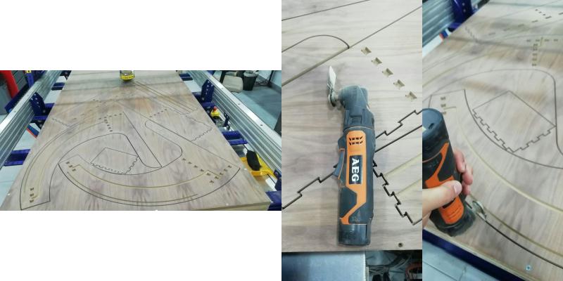
after the job is done its time to de-install the parts from the bord using a proper tool
Assemble