Computer controlled cutting
in this week i learn to use laser cutter and vinyl cutter it was an awesome knowledge in the beginning you must learn how to design then how to cut this design with cnc laser cutter machine later on i will explane these steps in detelse .
Group Assignment
CNC laser cutter
This part of the group assignment was about the trotec speedy 400 . We worked on all steps from starting the machine to engraving and cutting a sample on cardboard, MDF, plywood, and acrylic. then we make the kerf test on MDF wood and all of these tests explained on details down below

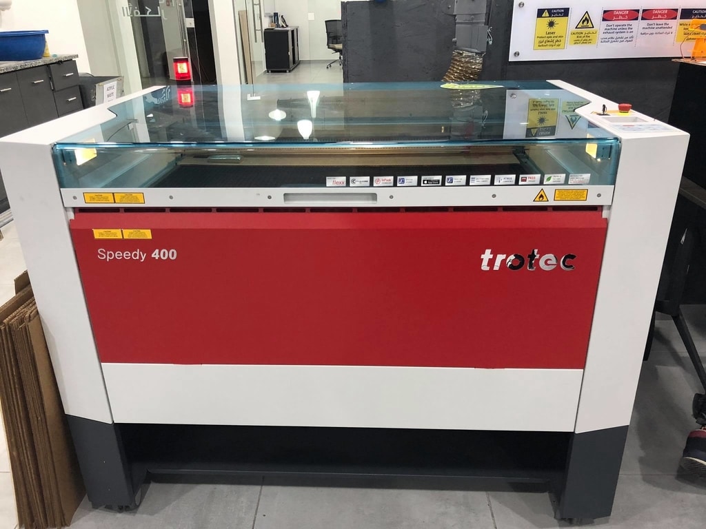
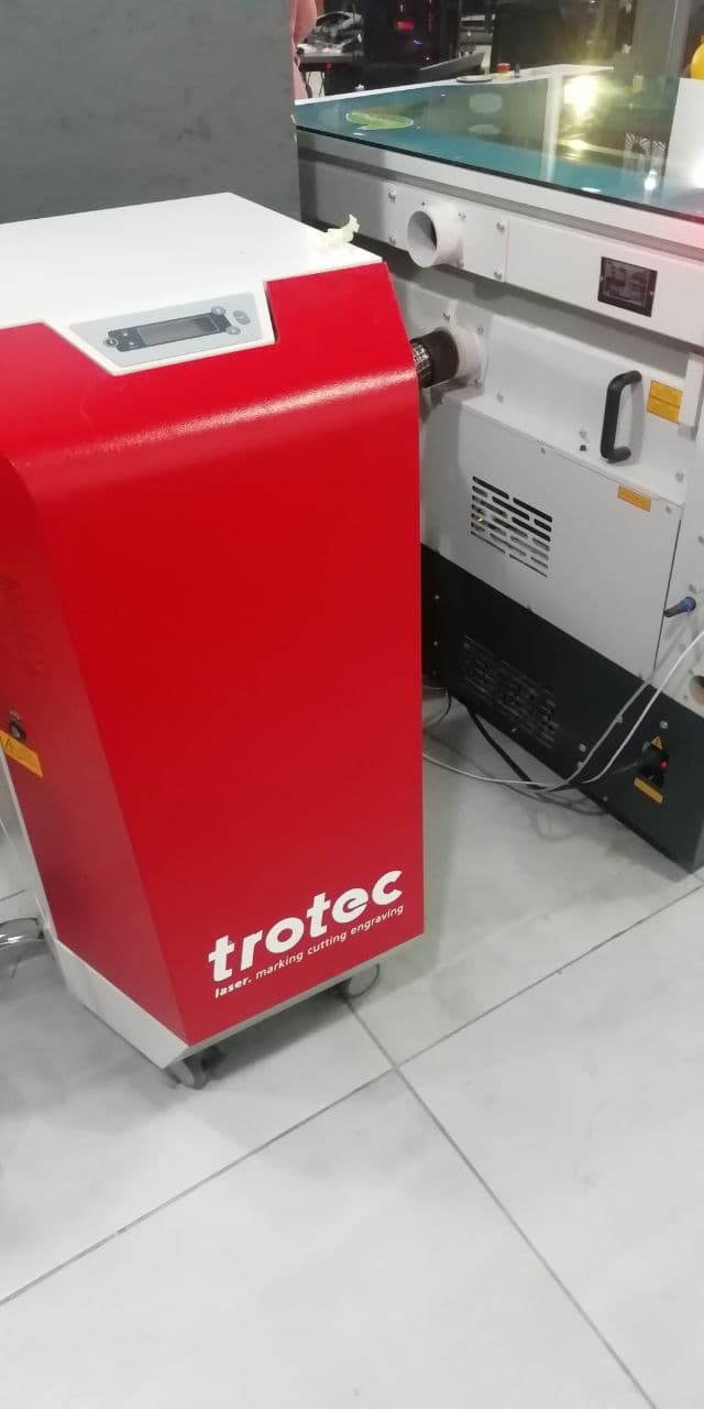
in TechWorks we use Speedy 400 trotec laser cutter
and because safety is first let's take a look at the safety instruction manual
- Only operate the machine while an instructor is in the room.
- Never leave the laser cutter unattended.
- Identify the fire extinguisher and fire blanket.

then we have to prepare the machine before cutting so important to see the control panel and recognize it
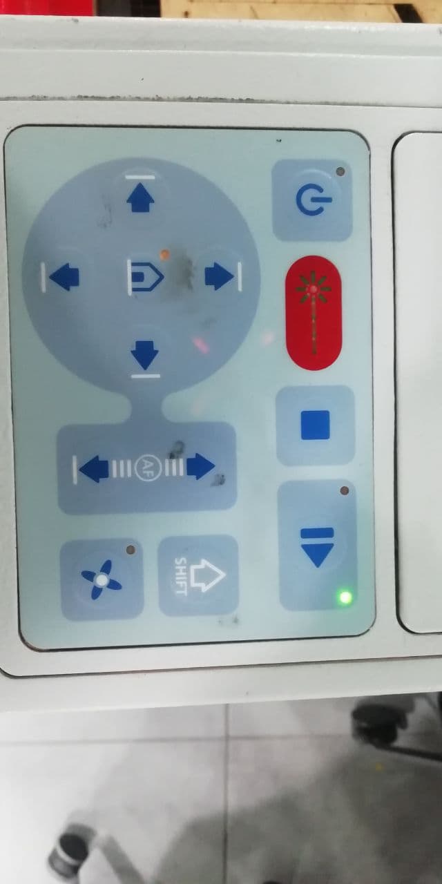
- 4 arrows to move the laser head
- home button to specify a reference for the laser head
- ON/OFF ,play and stop buttons
- shift button to speed the laser head up when its move
- fan button to turn on the fan for smoke suction
- up/ down buttons to move the bed vertically and focus the laser on the material
cleaning the laser lens
before starting cutting and machine testing, we have to make sure that the lens is clean and this is really important because of the lens is not clean you will not get the real laser performance.the main reason that the laser got dirty is long cutting jobs or bad using of the machine
the first step is to unscrew the lens by rotating it counterclockwise then bring it out carefully
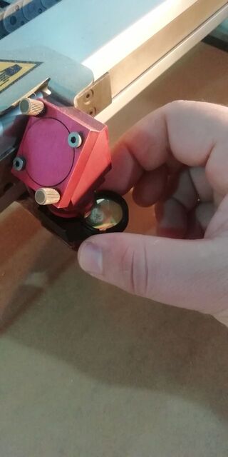
then use special wipes to clean it up and get it back to its place
Characterising the Power and Speed and Rate
We tested on:
- MDF: 4.75mm
- Transparent Acrylic: 5mm
- CardBoard: 5mm
- Phum : 3.5mm
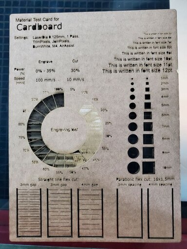
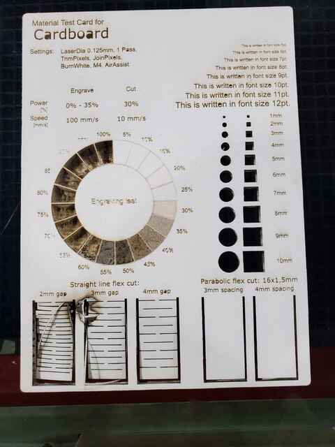
We started work with cardboard and select the following setting
| process | power | speed | PPI/HZ | PPI/HZ |
|---|---|---|---|---|
| engrave | 40 | 100 | 1000 | PPI |
| cut | 75 | 1 | 1000 | HZ |
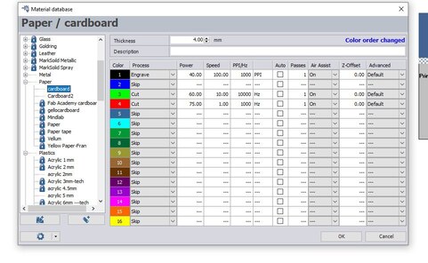
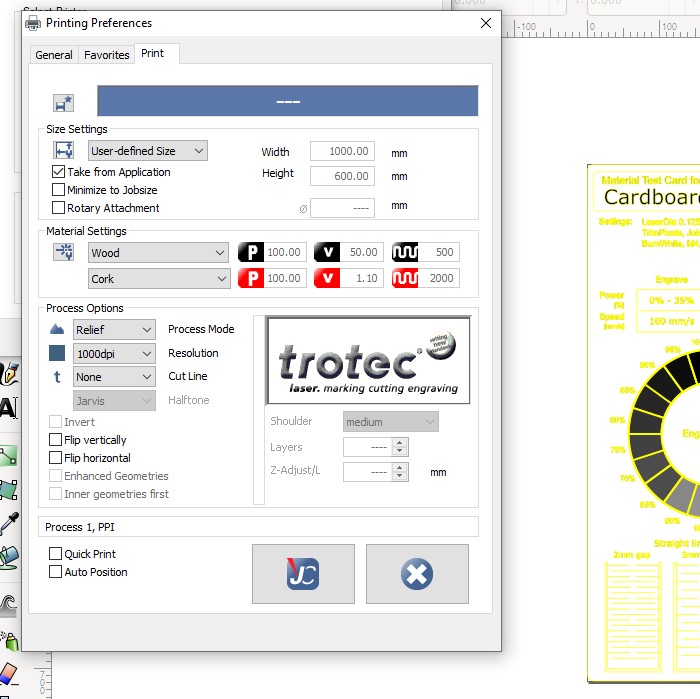
the first time we export this file to trotec software we got cutting lines without engraving job and after some tests, we find a solution. the solution was to make the cutting liens first then export the same file but with a different setting, now you have to specify the engraving area by gradual the white and black color only then press ctrl+p go to preferences>> print tap and in-process mode section select "relief" then press on the print button, if you don't see the engraving area that you specify before that will be a good indicator, now start the machine and everything will work perfectly
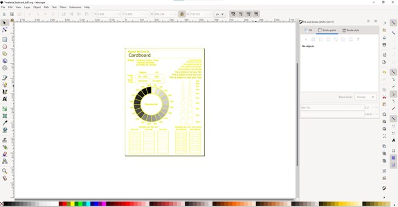
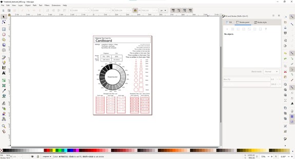
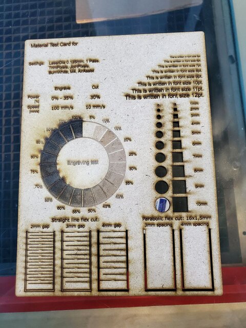
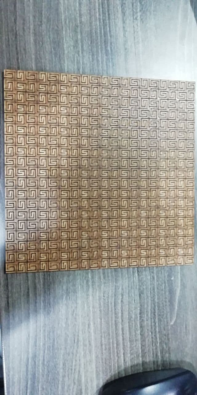
its work perfectly and the result was as shown done below
MDF 4.75mm
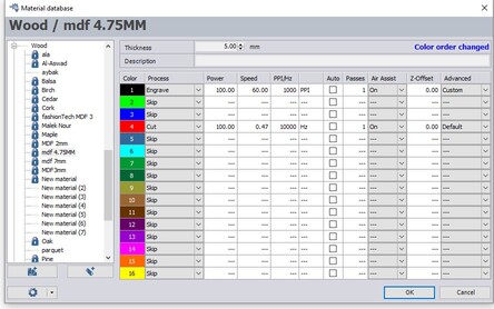
| process | power | speed | PPI/HZ | PPI/HZ |
|---|---|---|---|---|
| engrave | 100 | 60 | 1000 | PPI |
| cut | 100 | 0.47 | 10000 | HZ |
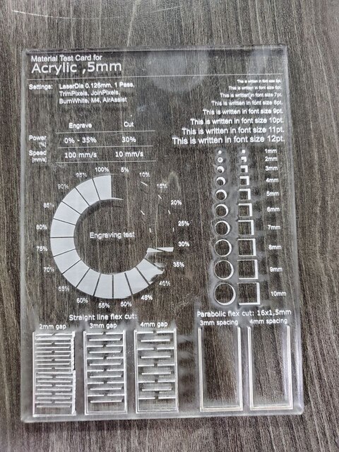
Transparent Acrylic 5mm
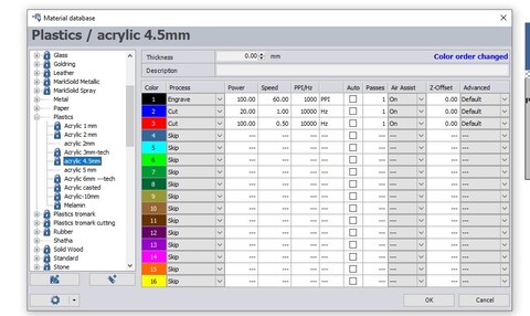
| process | power | speed | PPI/HZ | PPI/HZ |
|---|---|---|---|---|
| engrave | 100 | 60 | 1000 | PPI |
| cut | 100 | 0.5 | 10000 | HZ |
Phum 3.5mm after many tests, we use the same settings that we used on MDF wood and it works perfectly
kerf test
Here we come to the important part of the assignments. Kerf is defined as the width of material that is removed by the cutting process. It was originally used to describe how much wood was removed by a saw, because the teeth on a saw are bent to the side, so that they remove more material than the width of the saw blade it self, preventing the blade from getting stuck in the wood.
in the beginning, we made a simple design that contains 9 rectangles side by side with total length 100mm and cut them on a laser cutter, then we muser the total length of the 9 rectangels and it was 98.59mm
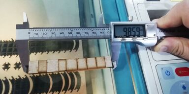
Kerf's equation is : Kerf = (Designed Length - Actual Length)/number of cuts
that's mean that the kerf is (100-98.59)/9=0.1555555 so kerf is 0.15555mm
Characterising the Focus
we have to putt the material then we have to focus the laser head using the focusing tool and you have to know that every lens has its own focusing tool which have defrent dimention
let's take look at the trotec software, I download a design just for testing on inkspace then i send it to the trotec software using CTRL+p
after that go the trotec software and the design will be there
laser cutter software is a color-sensitive that's mean you can cut type by coloring the design, here red color is for cutting and usually we use black color for greaving and so on, later on, I will talk more about settings and how to change it for different material and different purposes
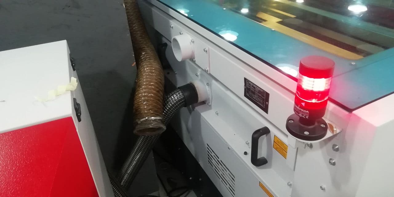
let's see how to set up the trotec. after taking the safety procedures we have to make sure that the suction tube is connected to the machine tightly and the other side is connected to a suction machine
after uploading the design and preparing the machine now we can cut the design
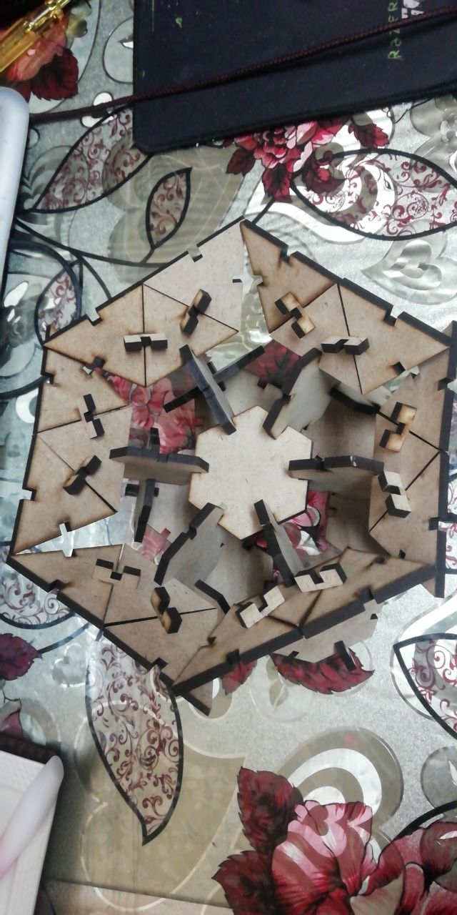
now let's go back to the beginning and explain each step with my design as example
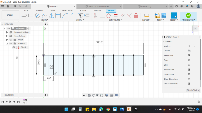
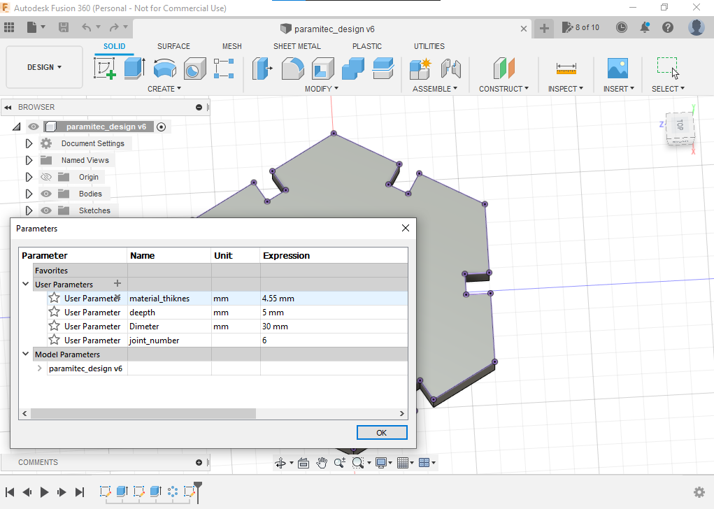
to make a parametric design in fusion 360 you have to go to Modify>>parameters then you can specify some variables (set names and values ) to use later. this step will allow you to change all the design dimensions by changing just one value, so its an awesome feature.
I made a parametric design on fusion 360 this is such a nice feature so you can make one design for different materials and thickness
to design my model parametrically I set 4 variables which are:
| variable | Description |
|---|---|
| material_thiknes | material thiknes |
| deepth | depth of finger joints |
| dimeter | diameter of the polygon |
| joint_number | joint finger number around the polygon |
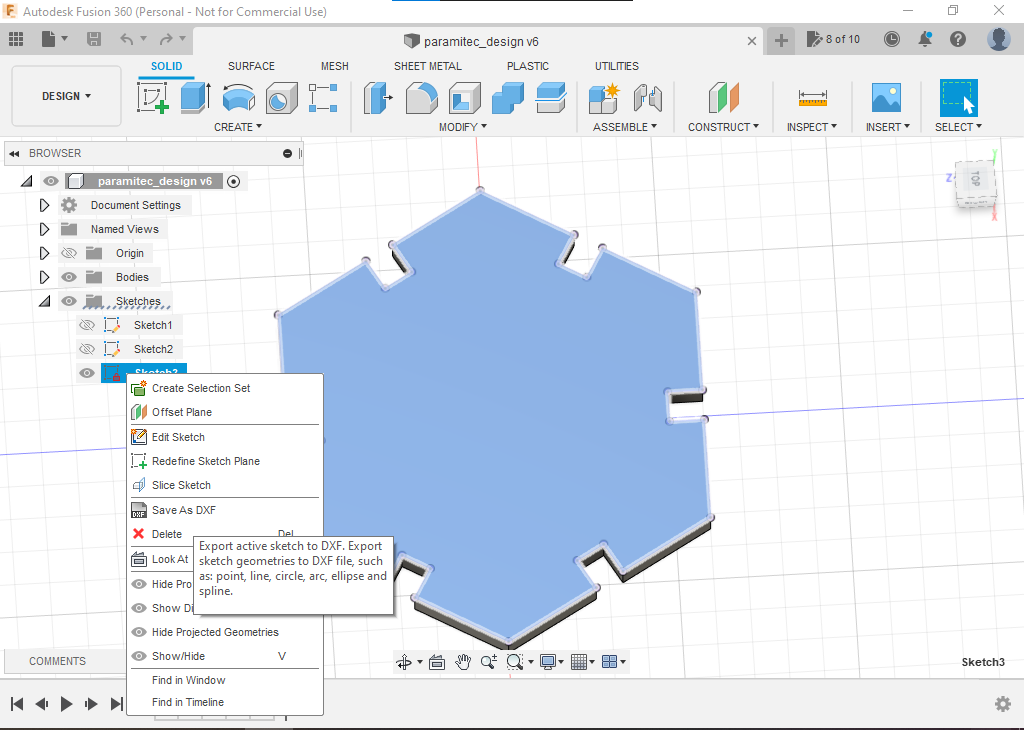
then I export the sketch design as dxf file to edit it and cut it
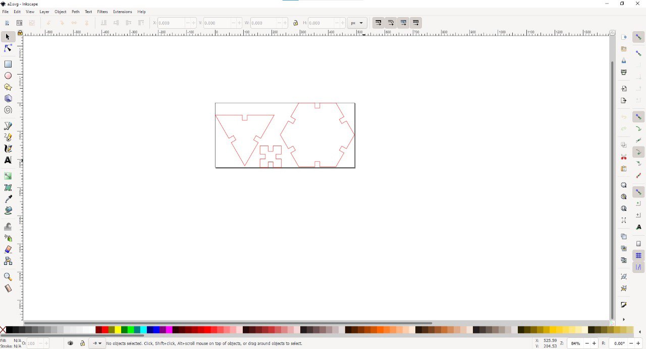
after open dxf file on inkspace we have so specified the exact color that we used on trotec software setting here I used red color to cut
press CTRL+p to upload the design to the cutter

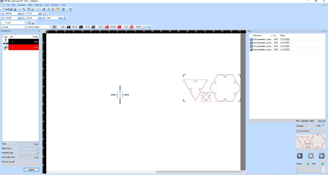
before cutting we have to check settings on trotec software and specify red color for cutting as in my example (of course you can make the red color for graving or make another color for cutting )
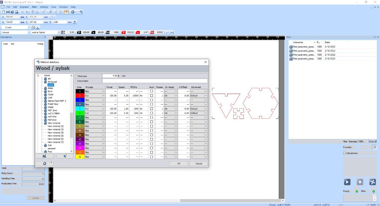
make sure that you chose the correct material and right color that you has specified before to get the result that you want here I cut on MDF wood so I choose wood and specify the power and speed of cutting by expermnt
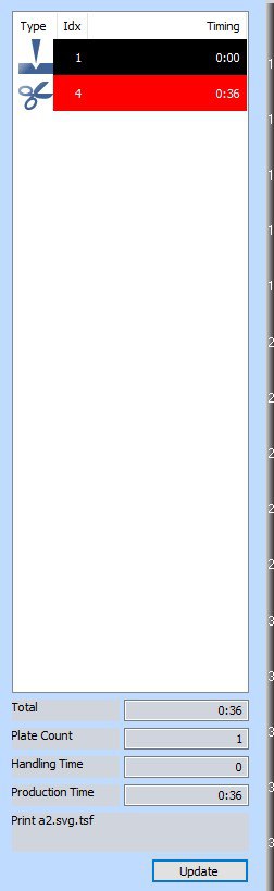
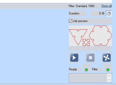
after that, you will see the estimated time to finish the job on the left side of the screen
and on the other side press play button to start the job and don't forget safety procedures
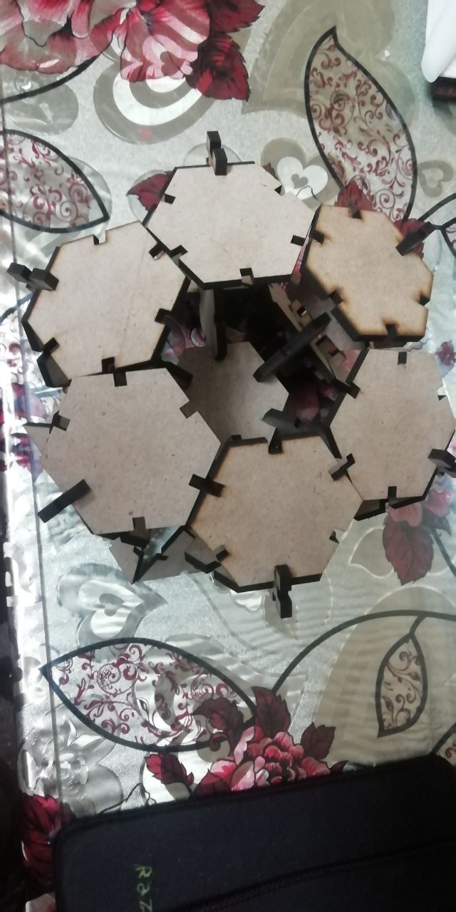
cutting process is in progress
Vinyl cutter
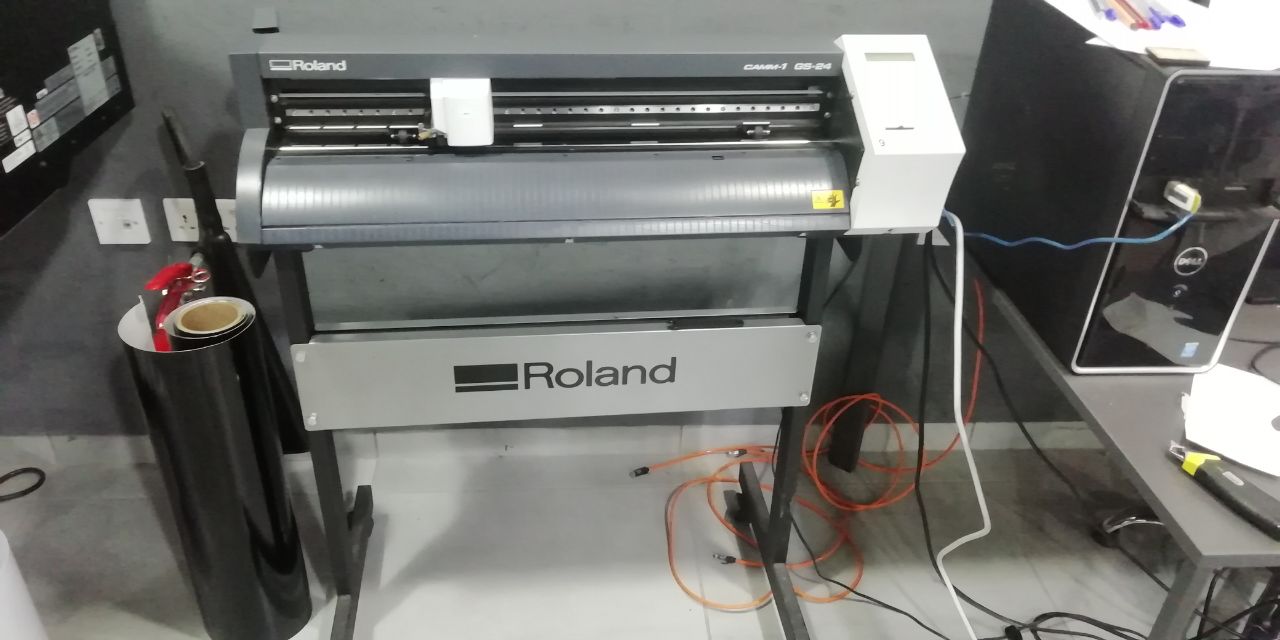
at TechWorks we have The Roland CAMM-1 GS-24 vinyl cutter
machine parts
the cutter head is mounted on the linear rail which is driven by digital controlled stepper motors for X-axis
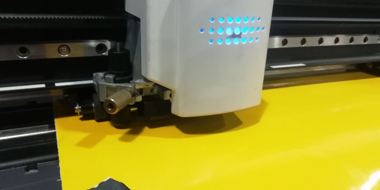
Y-axis is controlled by rolls which is adjustable to change the cutting space

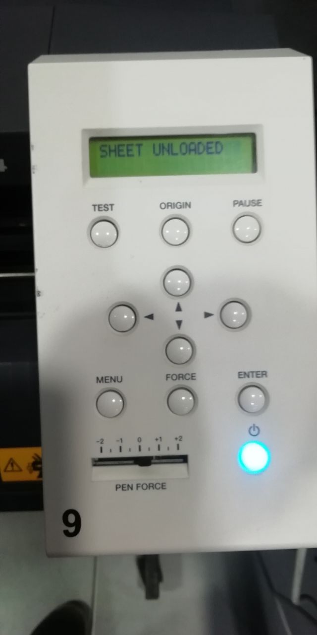
- in the control panel there is position control buttons that move the head left and right and the roll forward and backward manually
- test button for make small test for cutting settings
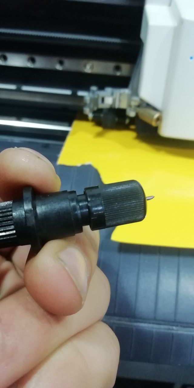
- PEN force slider to adjust head push force
this lock is for vinyl roll installation
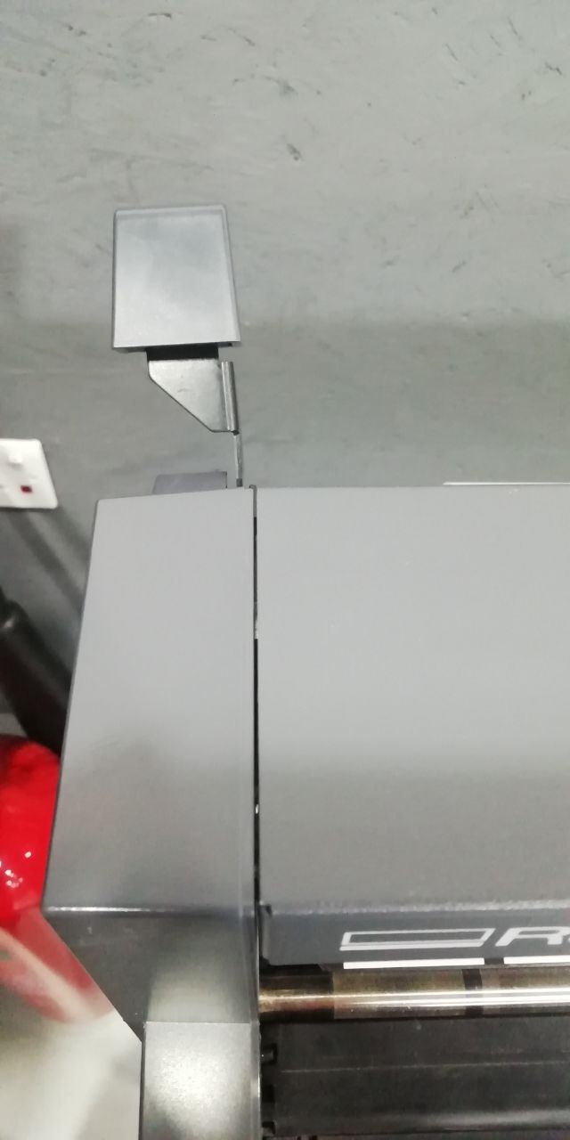
to supply the machien first of all you have to unlock the installation stick but the roll on its stand
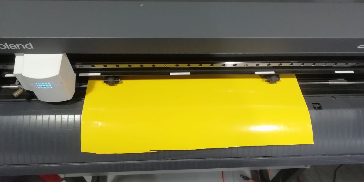
then make sure that the rollers is below the white bar to achieve the maximum friction and hold the vinyl while cutting
Let's cut a logo, i install a logo then convert it to SVG file using inkspace
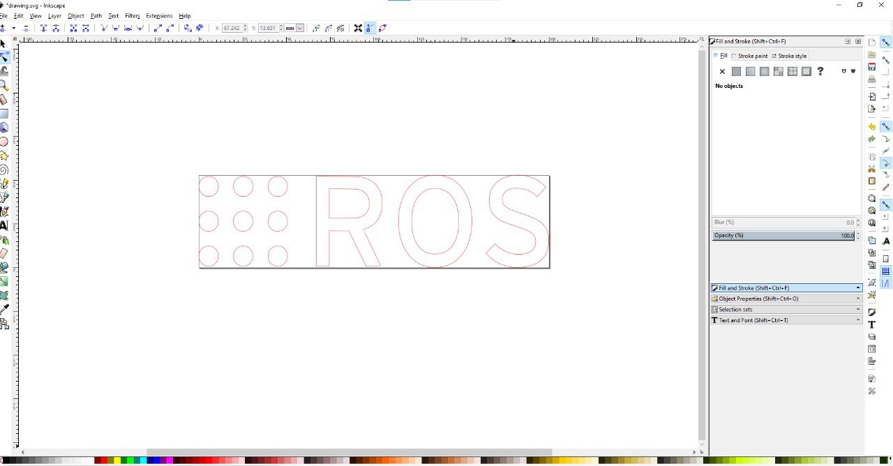
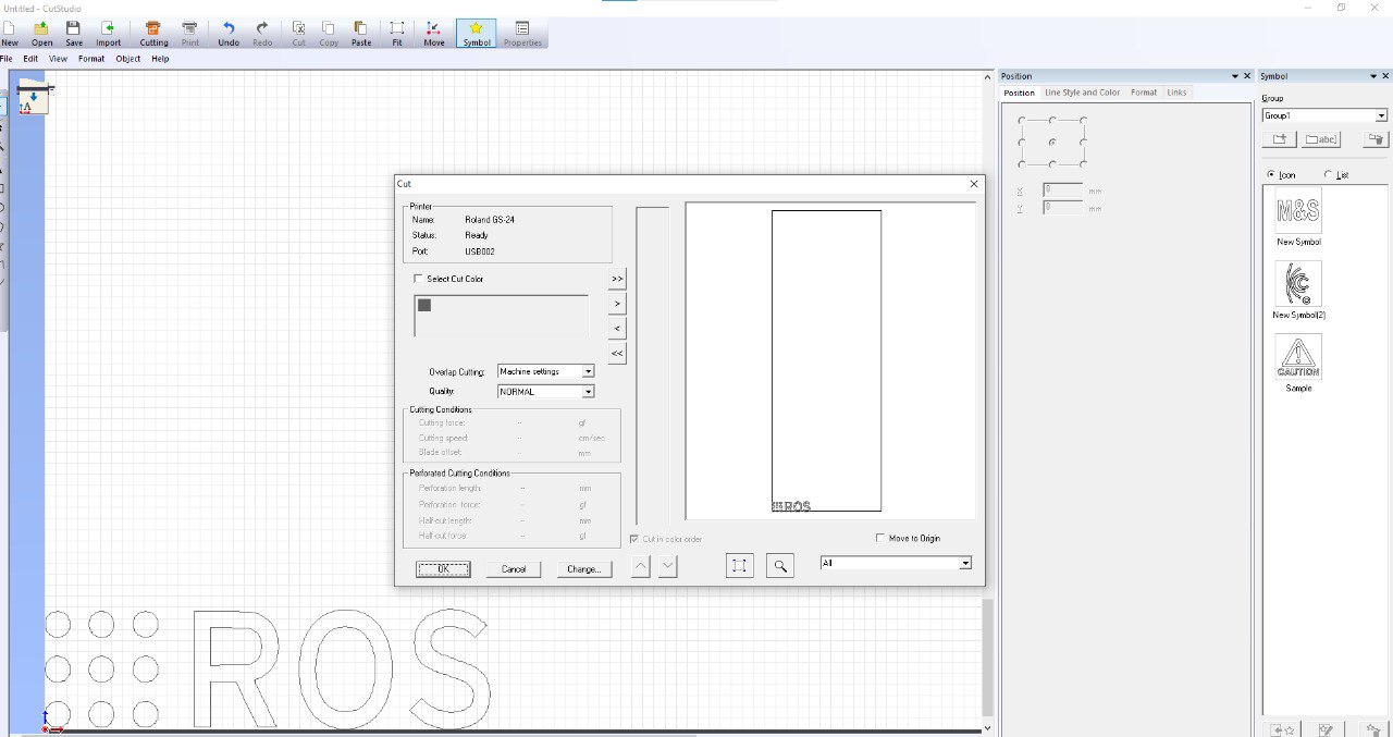
after that i take this file to cutsudio to prepare the design and upload it into Roland cutter
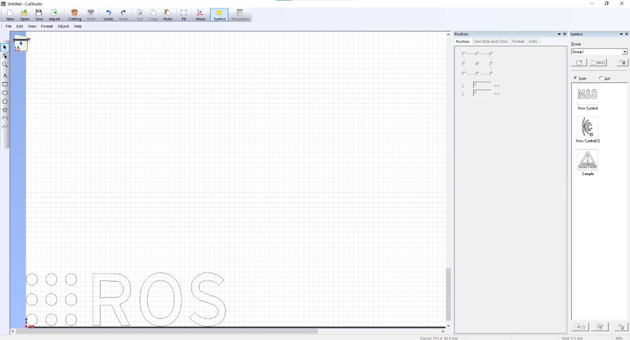
then press CTRL+P,ok to start cutting
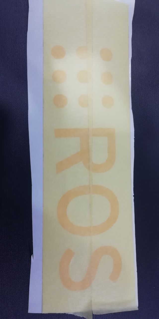
after the Roland cutter finish the job cut around the logo
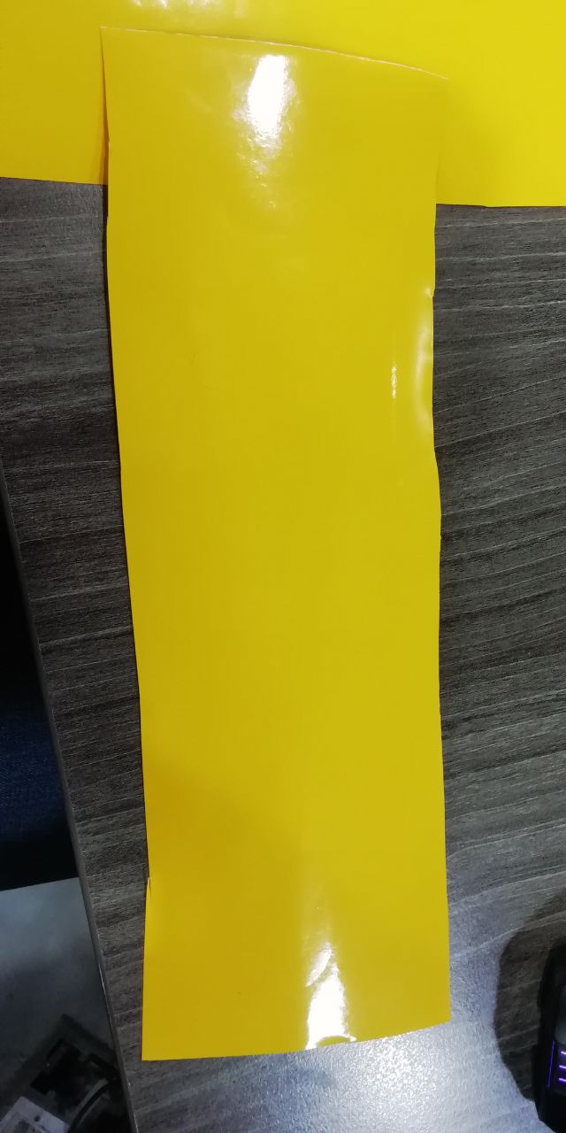
unload unwanted area
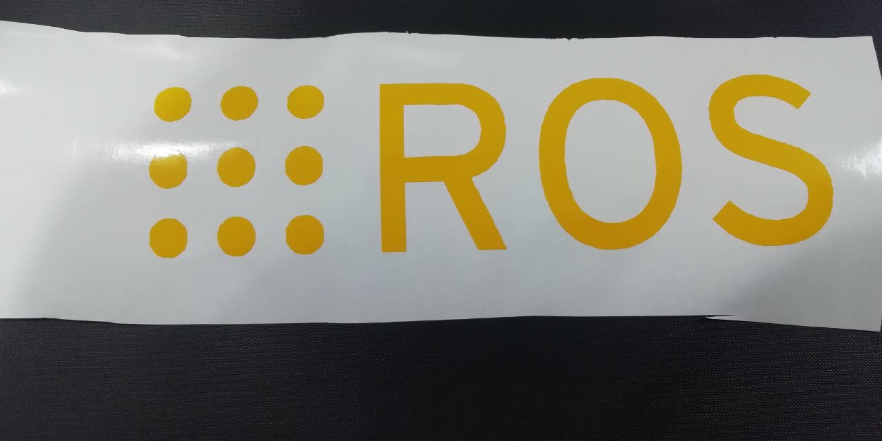
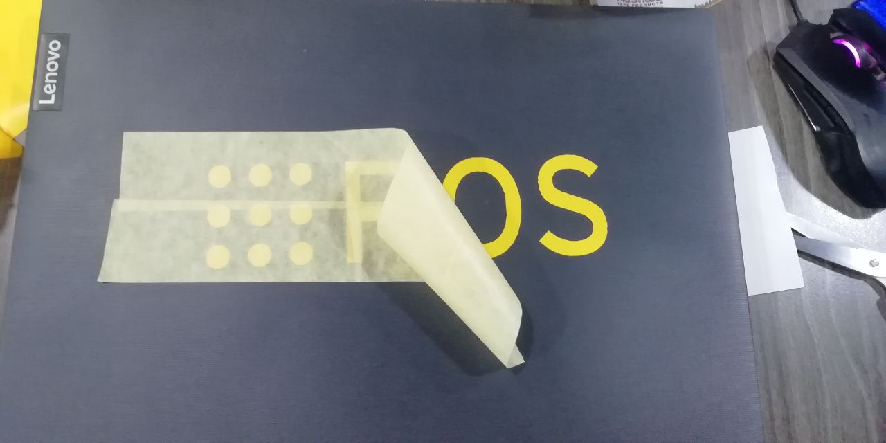
use transfer sticky to move the sticker to the place that you want
 s
s
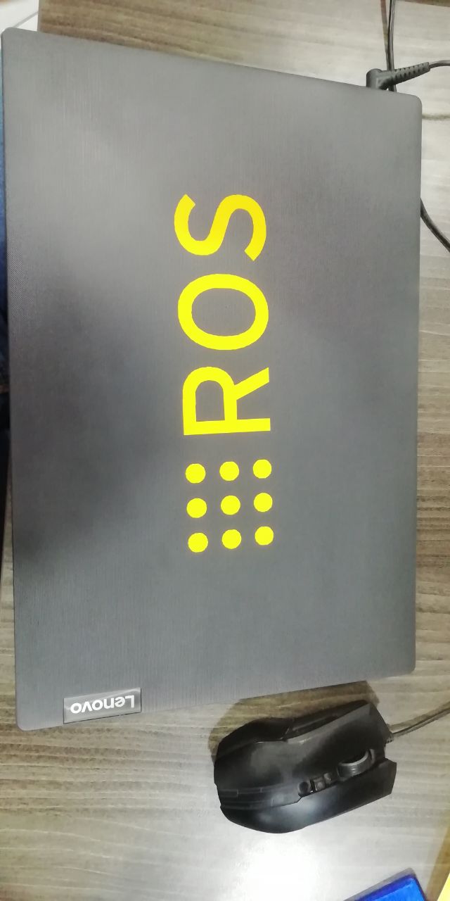
Hero shot
files to download
Google Drive
direct link