5. Electronics production
This week assignment is to characterise the design rulrs of PCB production process in relation with your PCB machine(s). Note the necessary settings such as feed rate speed, plunge rate speed, depth of cut for tracing as well as outline cut.
Individual assignment
The individual assignment is to make an in-circuit programmer that includes a microcontroller by milling the PCB, add the components and test if it works afterwards.
First step is to get the files. I used one of the class recommendation that can be found here
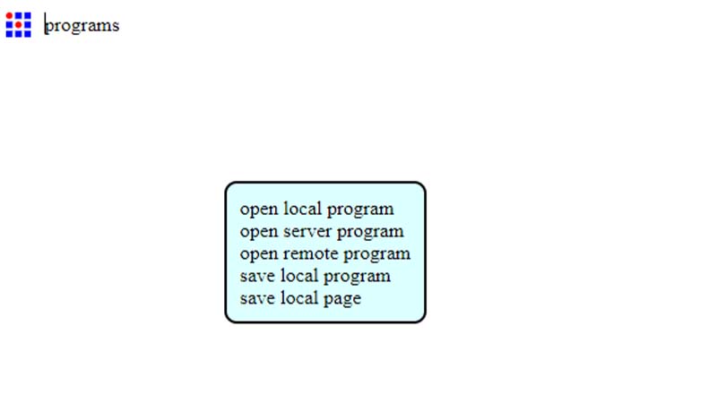
Start https://mods.cba.mit.edu/ This is the website I used to generate rml file. You can either use png or svg file format.
Right click and choose open server program
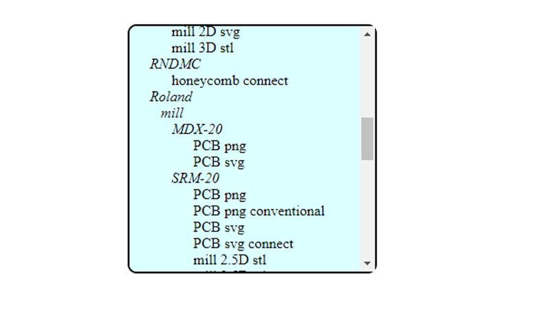
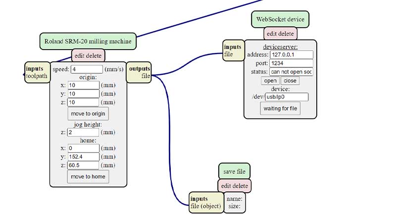
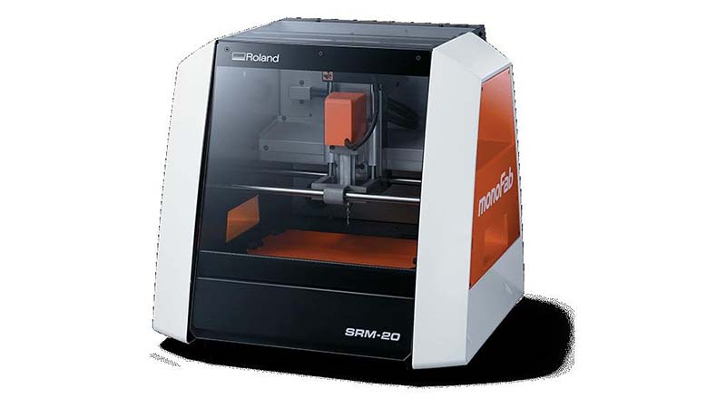
Navigate to search your machine type. It is Roland SRM-20 in my case
Import the file by selecting
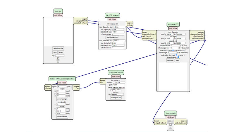
Set the origin, add save icon. I used this icon to export the rml file formal. After these stects, I connected the outputs file to that of the inputs
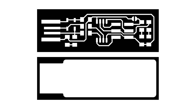
Next step is to select/check the mill traces (1/64)
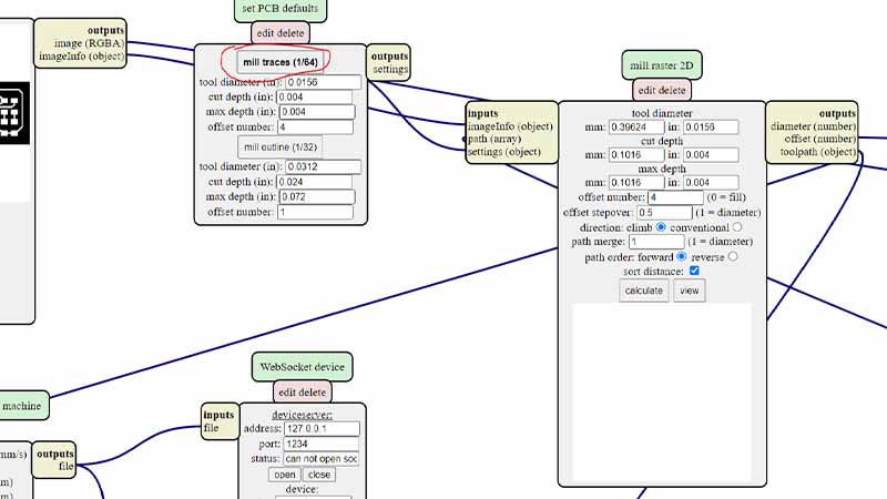
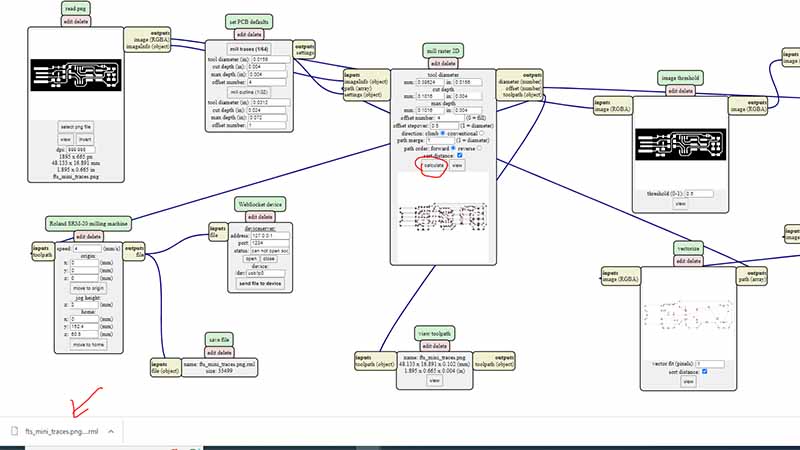
After that, I calculated the toolpath. At this moment, the file is downloaded automatically.
I repeated the same process for mill outline. This is the outline cut. Helps to cut out the board after millilng.
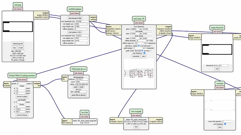
Preview of traces and that of outline cut
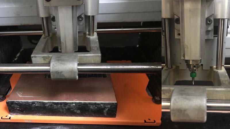
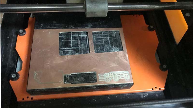
In-house machine
I added the board into the machine. Used double sided take to attach it the machine be.
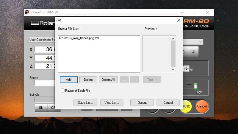
Next is to power on the machine and open PCB machine controller VPanel.
I opened machine controller to home all axes (x,y and z). by reseting all of them to zero valuse.
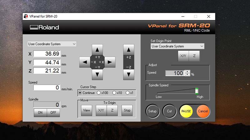
Aftern homing the axes is complete, I opened cut menu to add the file. After navigating the ile, next is to select output. and the machine start printing.
After tracing is completete, I changed the mill to 1/32 inch end mill
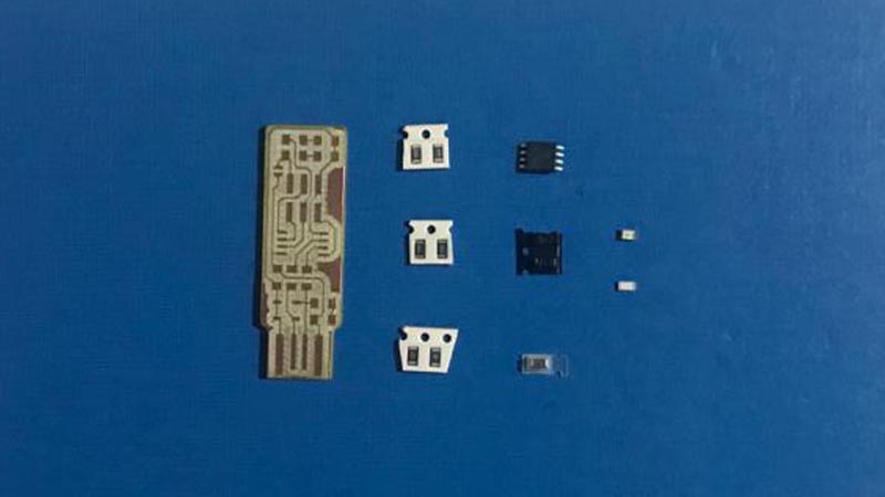
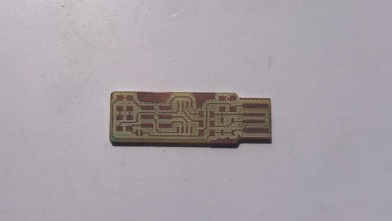
Final printed pcb.
Soldering the components
List of parts needed
- 1xATtiny45
- 2x 1kΩ resistors
- 2x 4991Ω reistors
- 2x 3.3v zener diodes
- 1x red LED
- 1x green LED
- 1x 2x3 pin header