INDIVIDUAL WORK
In this week I really drooled. The week of networking and communication.
In this week I started using the ESP32-WROOM-32D. But I got stuck in the programming of the ESP32. I didn't have an initial programmer. But I used the FTDI cable to program it on the Arduino IDE, alas I had an error signal. But I changed my mind. So I had the idea of using two microcontrollers to exchange information between them.
Here is the idea in question, one of the microcontrollers is lucky to take information (a PWM signal) from the other and use it to control the lighting time of its LEDs. In both circuits I use attiny45 microcontrollers.
The operation of the first microcontroller that I call master. In the first circuit the attiny45 reads the value of the LDR connected to its PB3 pin, and provides a voltage at its PB1 output. The output voltage is a function of the signal supplied by the LDR.
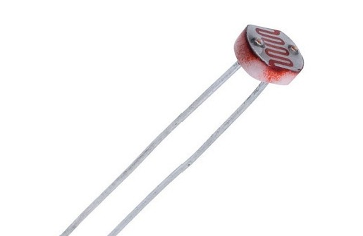
An LDR (Light Dependent Resistor), as its name suggests, its resistance varies according to the luminosity. Its resistance increases when it does not detect light, it can go up to 72.7KOhms when you hide its surface with your finger. Its resistance drops when it detects more luminosity, it can go down to 0 Ohms.
Schema Circuit
Regarding the operation of the second circuit which I call slave. Pin PB1 of the first circuit is connected to pin PB1 of the second circuit. So the second circuit reads the value sent by the master and maps this voltage into a time value. This time value is used to give the lighting duration of the LEDs.
The connection of the two circuits, master and slave, is made through the ISP cable having two heads. I designed it in the lab with Conn 2X3 heads.
Circuit design with eagle software.
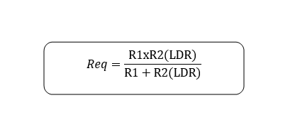
The circuit of the master. I started by opening eagle, as I already know the attiny45 microcontroller, I didn't do any research, so I drew its functional circuit. Then I added a voltage presence LED, then on pin PB3 I made a shunt wiring between a 10KOhms resistor and my LDR. By the calculations whatever the value of the LDR, the value of the total resistance read at the level of the pin PB3 will always be lower than 10KOhms. I did the outline too.
This is the law of resistors connected in parallel.
Eagle schematic master
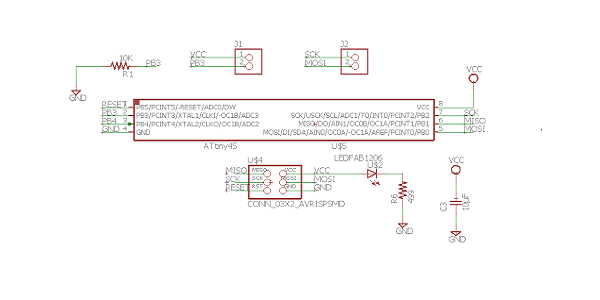
Eagle circuit master
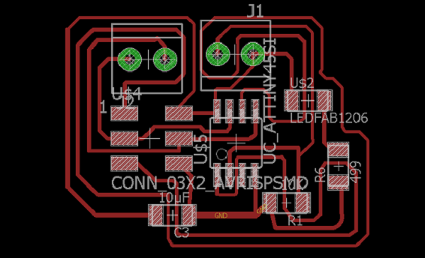
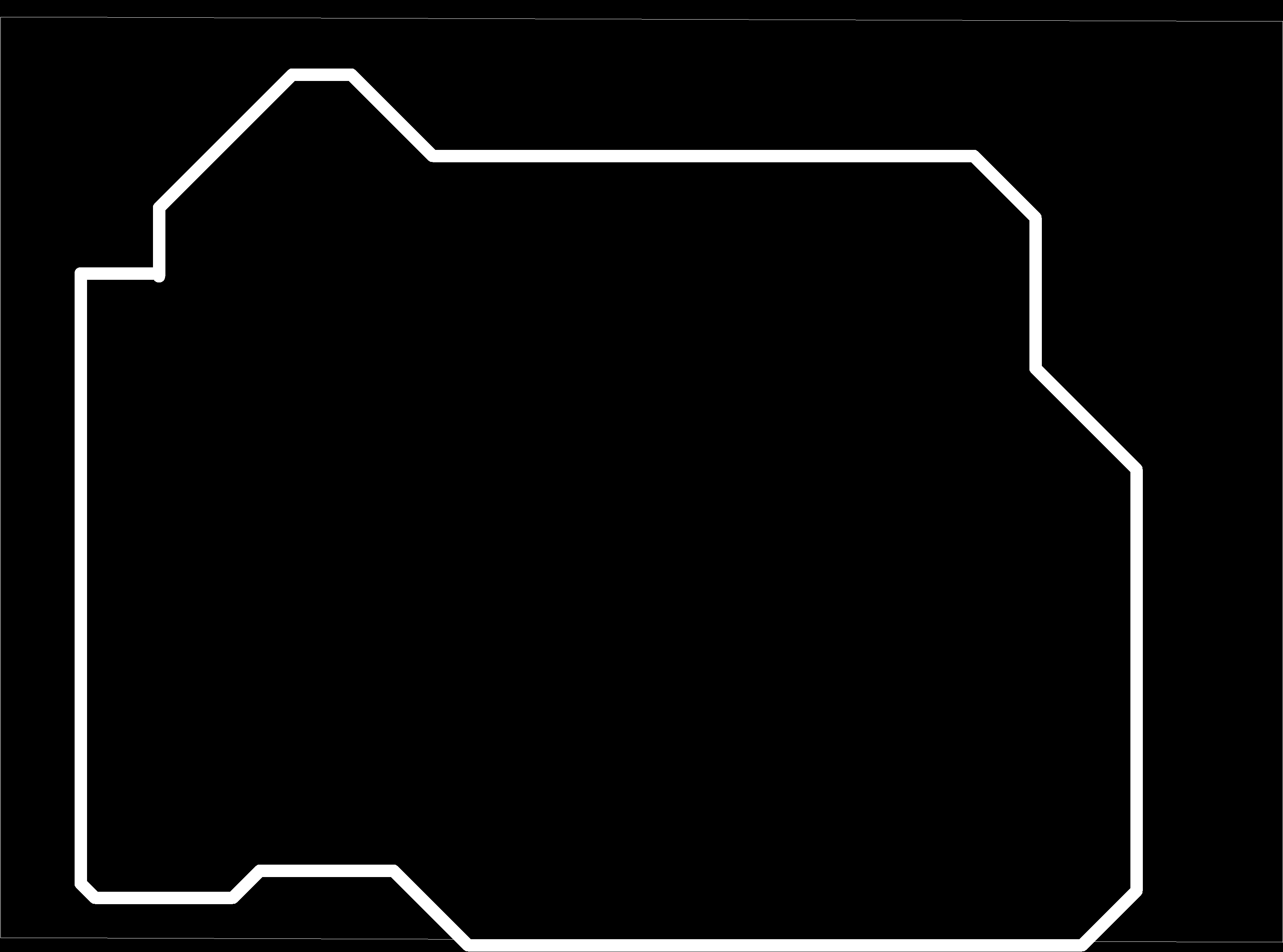
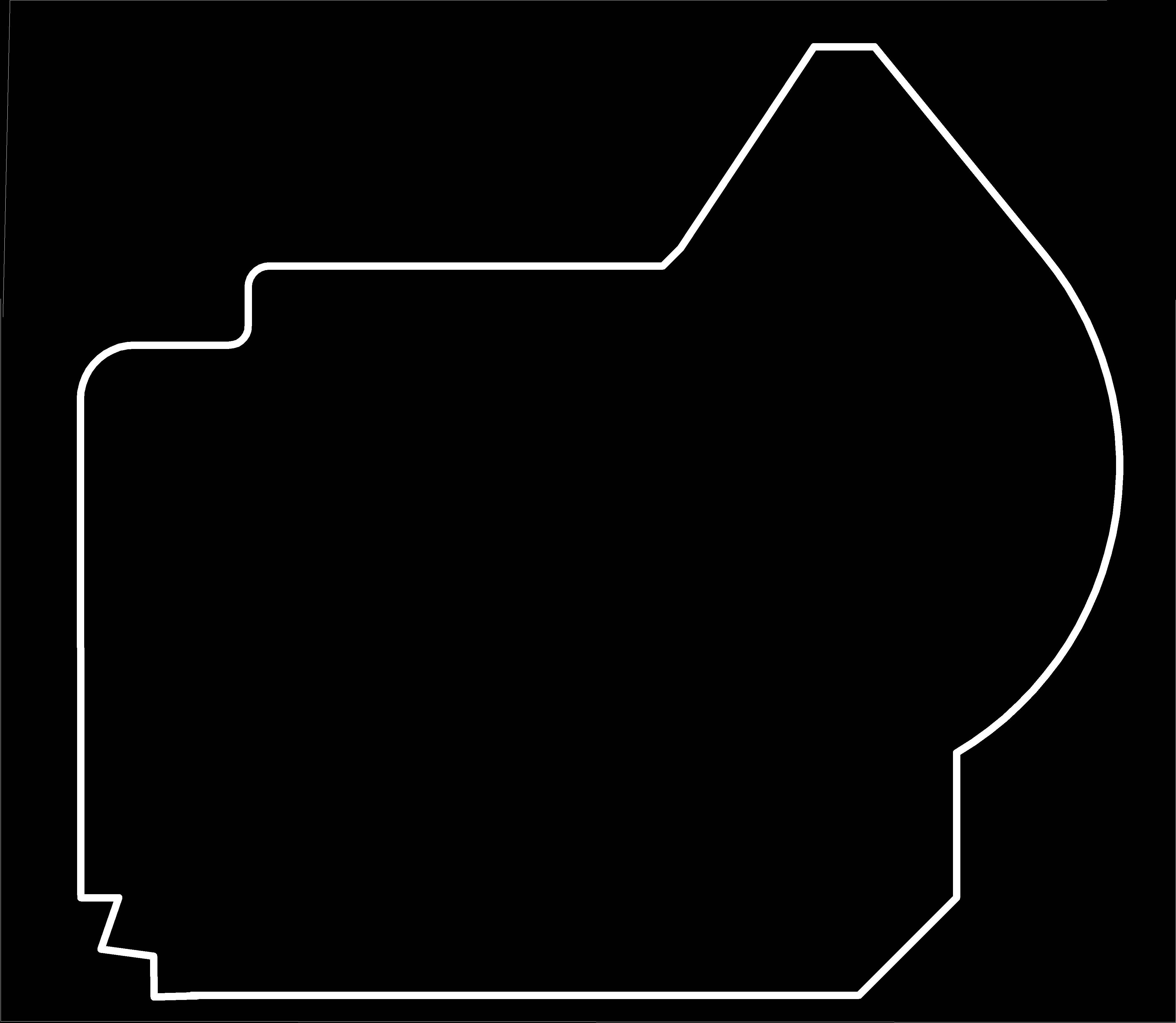
After the realization of the circuit I transformed it in image mode. This image will be transformed into a circuit in the aspire software. The aspire will generate a G-code having the layouts of the compressible circuit by the Modela MDX-50 machine.
circuit
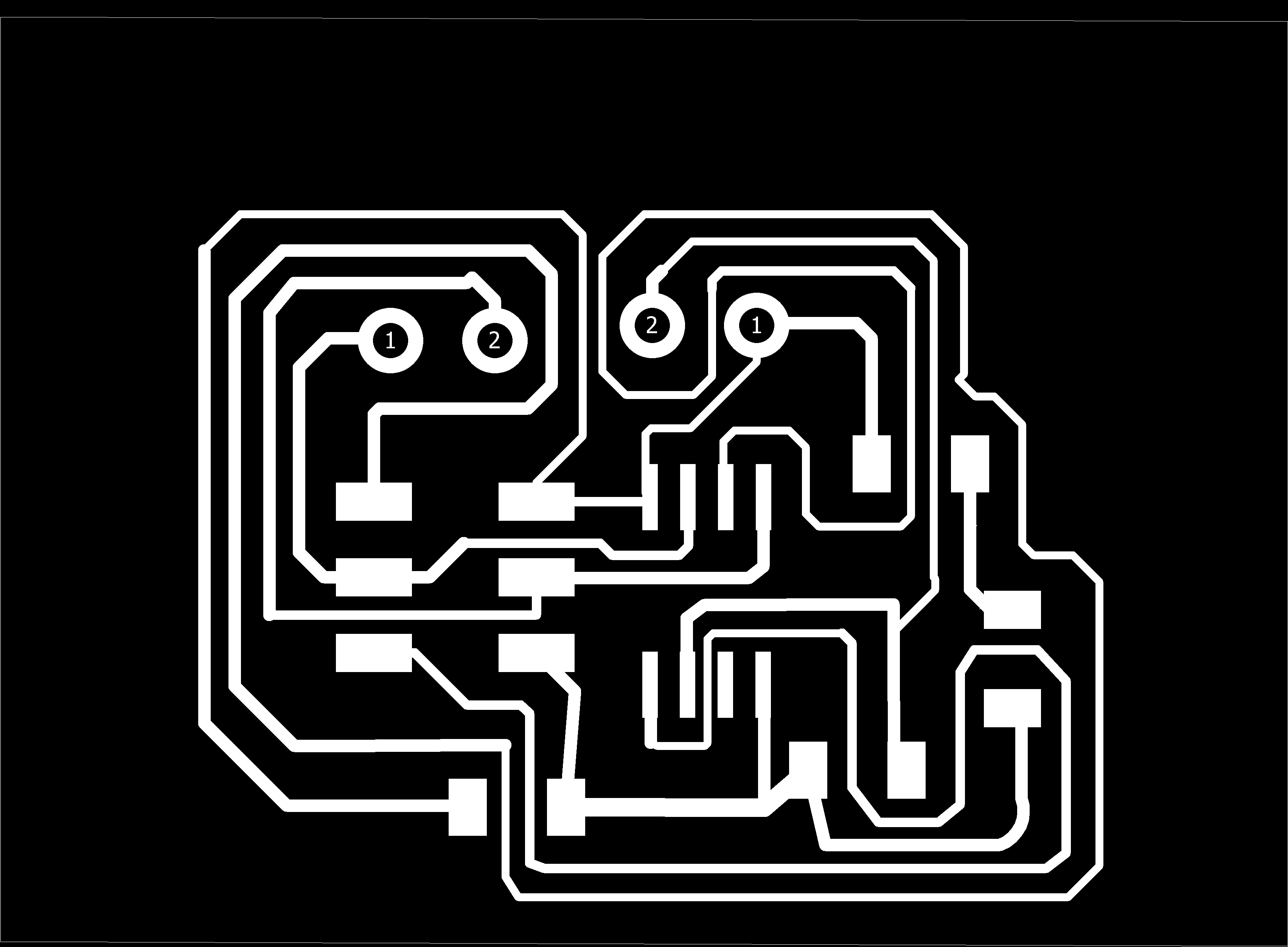
bord
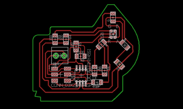
The slave circuit.I edited the master circuit, I placed 3 simple red, green and blue LEDs and an RGB LED. I connected the leds of the same color to each pin. Red Led PB0, Green Led PB4, Blue Led PB3; I connected their common anode to Vcc. I had some difficulty to place the leds in 45 degrees, but I could. You had to click on the led and write the corresponding angle. I placed the RGB in the middle of the three leds placed in the shape of a triangle, and I really loved the positioning. After tracing the circuit, I made the edge outline.
Eagle schematic slave

Eagle circuit slave
The slave circuit in picture.
Circuit
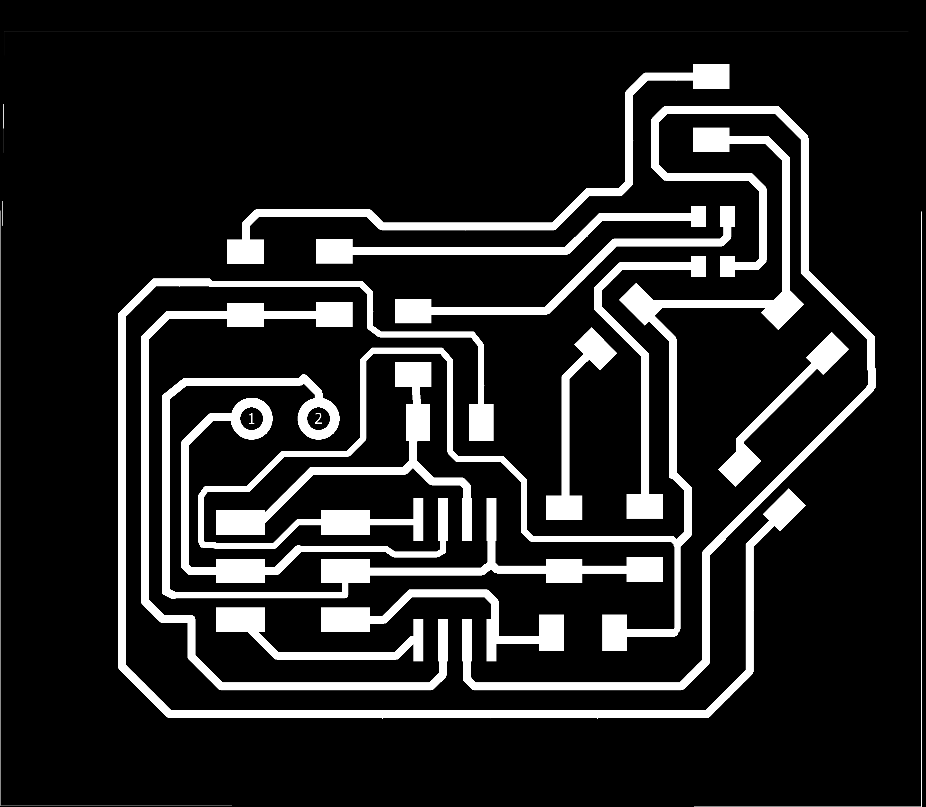
bord
The generation of G-codes with the Aspire software.
After designing the circuit it must be printed. But before being printed it must be processed and generated a G-code. To do this I open my Aspire software, I create a new folder. I import the master circuit, I click on the image and I click on the Bitmap function. The parameter that opens I set the visibility of the circuit, the roundness at 100%, the number of pixels at 2 and the Contrast at 52%. Then I click on Preview and Apply. And closed. I then click on the image, this turns black and I click on the delete key on the keyboard. There remains the circuit. I select it and I ungroup. I remove the double outlines. I did this for the slave circuit and the two contours. Then I grouped each contour with its circuit.
Circuit positioning. There was already a milled PCB on the machine, it still has room for my circuit. So I opened the previous eagle file and took the coordinates to place my two circuits. I placed them.
To continue I must first drill the circuit holes, then mill the circuit, and finally cut.
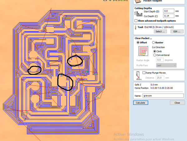
On the modela MDX-50 machine I changed the bit to 1/32inch for drilling. On aspire I selected the grouped holes then on toolpath I click on the drill function. I saved the G-code. Finally on the Vpanel I choose my file and output, the drilling took me 1 minute. After drilling I changed the bit to 1/64inch. I clicked on toolpath again and on engraving, I set the engraving thickness to 0.14mm; then I chose the 1/64inch wick, in D=0.38mm. When I finished for the parameter I selected my two circuits then I clicked on calculate. This generates the circuit route. I checked the slave circuit there was no problem. I checked the master circuit but there was a short circuit in 3 points.
Short-Circuit
I edited the parameter and I have the D=0.32mm but it was the same thing. So I edited the diagram on aspire by ungrouping my circuit. Then I reduced the width of the tracers at the corners where they touch, then at the level of the legs of the attiny there is one of the pins that I did not use, so I deleted it to make room for myself . Then I grouped my circuit then recalculated but the software told me that there were parts of the circuit open, so I ungrouped then I deleted where I modified, so I saw the pieces of lines, I made control Z to bring back the deleted part, then I Zoomed and deleted the small lines. Then I grouped then calculated. All is well. I selected the two circuits and I calculated, finally I saved the G-code. In Vpanel I launch the burning, it took me 23 minutes.
circuit without Short-circuit

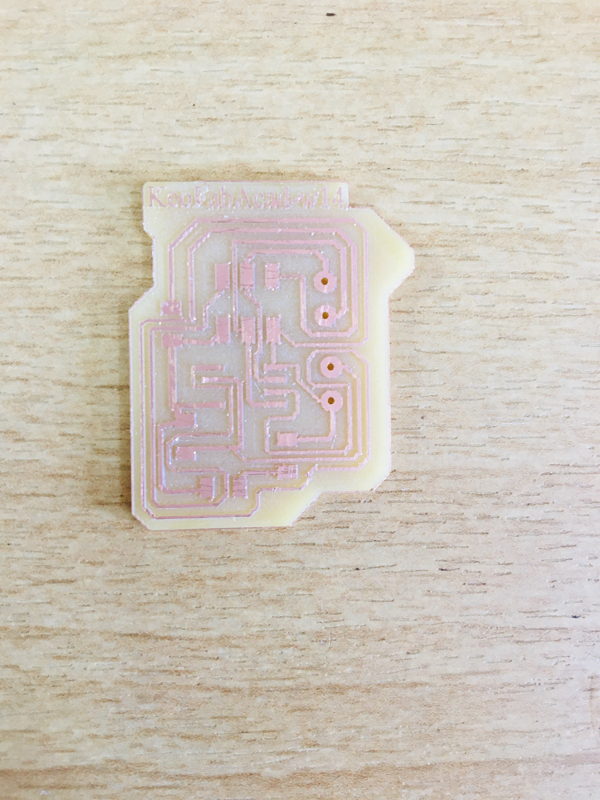
Finally I select the edges of each circuit, I change the wick to 1/32inch and I start the cut.
MASTER PCB
SLAVE PCB

The welding part.
As usual I suddenly all circuits then tested for perfection and shorts with a multimeter. There is no short circuit problem.
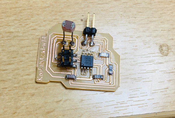
MASTER WELDED
SLAVE WELDED
Programming.
On the programming side I used the Arduino IDE. I first programmed the microcontroller for the master circuit then for the slave circuit.
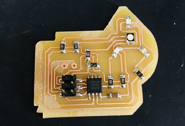
The master circuit program,the microcontroller reads the resistance value on pin PB3; then we use the map function to reduce the value and assign it to pin PB2, which must output a PWM voltage;
But that did not give, I measure the output voltage of the PB2 are 0. volts. I checked the connection of my LDR, but it was not in its place, I placed it correctly. Then I re-measured but it's the same. I connected to the oscilloscope to see my signal but it was in zig zag even if the resistance does not vary nothing changes. So I figured out that the PB2 pin does not support PWM signal and I had a lot of trouble before I knew it.
Oscilloscope signal from pin PB2
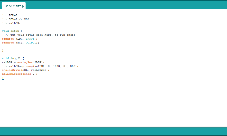
So I changed the output pin and took PB1. In the code I used pin PB1 instead of PB2.
When I repeat the same measurements, it works perfectly, the voltage varies according to the brightness.
Oscilloscope signal from pin PB1
The slave circuit program, in my program I had put the PB2 circuit as an input pin. So I modified it to pin PB1. Then I connected the PB4 pin to the green led. The PB1 pin of the slave is connected to the PB1 pin of the master. Then we will read the incoming value of the PB1 of the slave. We use the map function to increase the value of the signal from 255 to 5000. This value is used to give the lighting time of each LED.

Operation. If the LDR detects less brightness the LEDs flash faster, if it detects more light it flashes every 5 seconds.