Working Group
INDIVIDUAL WORK
In this week of input device I have to use a sensor as input and read its value. The sensor on which I will work is the water level sensor. This sensor will allow me to measure the humidity level in a given floor space.
Water Level Senso1

When I read tutorials on this sensor, it has 3 Pins, gnd, vcc and S. Pin S sends us water level data.
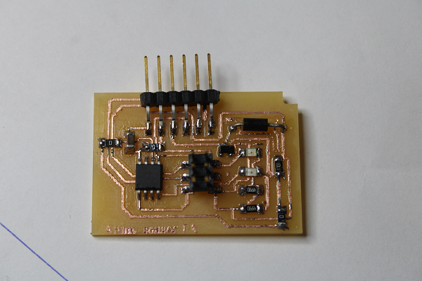
Now I designed my circuit with the ATtiny45 microcontroller; I just edited my ISP fab circuit. I added an output pin, kind of for powering a pump when the water level is down. I will equate it as. You could download my eagle file at the bottom of the page. I milled my board and took the necessary components.
Milled Circuit

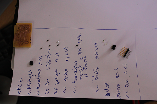
Components
Weld result
PCB
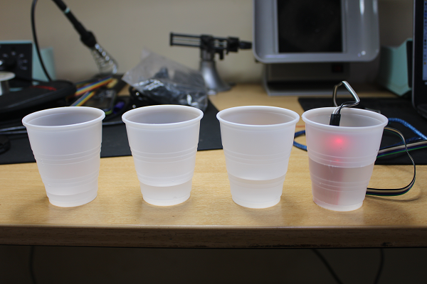
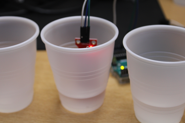
I put water in plastic boxes in different amounts.
Water in the four plastic boxes
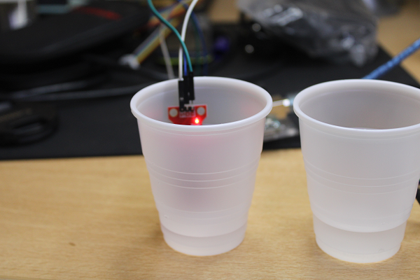
Now let's get to the wiring. I soldered some files between my sensor and my board. The GND and VCC files at 3V are connected together and pin S of the sensor is fixed to pin 3 (PB3) which is an analog input, this to increase the range between my card and that of the box.
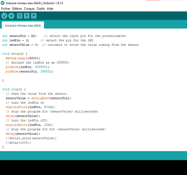
I will write my arduino program to read the value from my sensor. I uploaded my program to my attiny45 card, upload error, problem the Serial is not declared. I double check my program all is normal. Second try same result. I uploaded the program to the arduino board, its working. I take advantage of connecting my sensor to read the values. I insert my sensor in the water box, everything displays. I knew now that my attiny does not take into account the serial monitor (Serial). The sensor without water gives a value of 0. In fact the value read is a resistance, the more water there is, the more the resistance increases. On the serial monitor here are the first takes.
Arduino First CODE

The value in the first box was 162.
The value in the second box was 189.
The value in the thirst box was 199.

The value in the four box was 213.
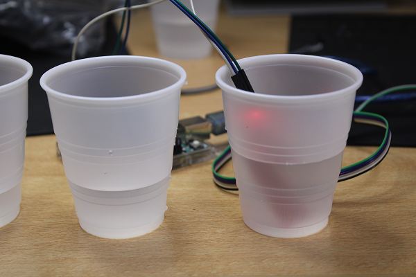
Now I will reconnect my sensor with my circuit. Then upload another program without the serial monitor. The Code makes it possible to make the LED connected to pin 2, i.e. PB2, flash according to the value of the sensor, i.e. the water level. I uploaded my program to the attiny45 board. I deposited the 4 cups, the water level of each cup is delayed. From the smallest to the biggest. Then I immerse my sensor in each pot and we see that the flashing speed decreases according to the water level.
The second arduino code
First Movie Experiance
Now I will define in my code at what water level my engine will start and stop it when the sensor value has a certain level. Normally my motor is equivalent to a pump. (I prayed the poly tank example. I connected my motor to pin 4 (PB4). In my program I defined that when the water level is down from 170 turns on the motor and when it is at 200 stops the engine The code is at the bottom among the download files.