In this week 08 we worked on the Shopbot machine.
WORKING GROUP
The group work consisted of :
1. Utilized shopbot to cut an object to measure the different dimensions as the angle of 90 degrees then compare it with another object cut with laser epilogue, we used wood (against plate of 18)
We drew our object first on SolidWorks,
Then convert it to dxf file. To convert the file to dxf you have to place the object on the flat side that is to say that the look will be in 2D; and we make save under in file type choose dxf and save.
Afterwards I copied the dxf file into a personal key and copied it to shopbot's computer. I opened aspire and then we placed the object on the blank page. We used guides to position our object. In toolpath we have chosen the parameters:
After configuring the suction settings,
we started the shopbot machine by running on the boot contact, and we opened the shopbot driver software called shopbot3 on the computer intended for the machine. Then we configured the machine to the coordinate 00 of XY then we made the Z0. Let's start cutting our long-awaited object. We click on Cut start then we choose our piece then we click on start. Attention here, on you click on the OK you will lose your here, on having clinker on start you have to click the start button in green to turn the thin. We now click on OK. The cut took about 5min. The Speed was not much, and the displacement was less lent.la machine cut it at its own pace but we compared the result with the same object cut with laser epilogue.
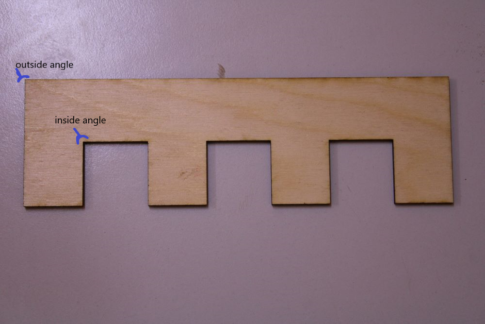
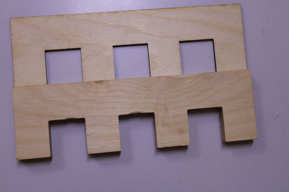
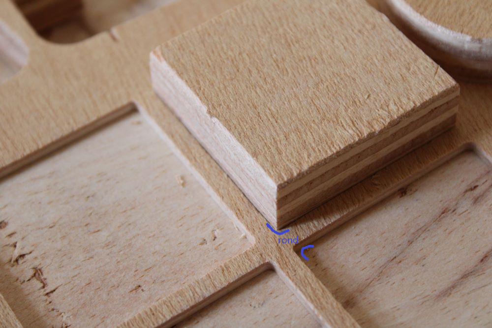
Shopbot Cut

A new piece was cut using power from 25% and a Speed of 50%.The angle is correct and the round is almost not visible.la measure with De Theset square correct.
Epilogue Laser Cut
NB: For more in-depth knowledge on the use of software and its machines , be sure to refer to my assaignment of week 3.
Assaignment week 3.
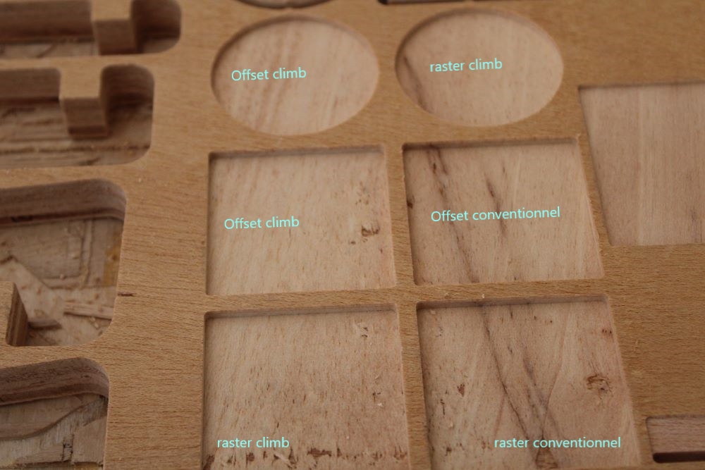
2. Planing quality was tested using raster and offset functions and climb and conventional subfunctions.
In this test we knew how these different functions work. But the sub-functions are almost the same.
In the raster function, when cutting the object, the machine cuts by scanning along the X axis. at the end makes a turn on the outline of the object to make the dimensions normal.
In the offset function and sub-functions climb the machine by from the middle point of the part and cut according to the radius of the green circle the outside. With the conventional subfunction the thin cuts from the outside to the inside following the circle.
We have engraved in utilison a thin end mills of 3mm. 6 tests were carried out with the Same speeds of 15000trs per min a speed of displacement from 30%, a pass depth 2mm, stepover of 35%. The result was the Same. The precision, quality. We found during the engraving, in the offset part climb the machine vibrates a lot but concerning the raster no. This is à what the machine does very small strokes before going out;
Now for the rest of our operations we use the raster function.
Wood planing With Shopbot for Differents Fonctions
Measurement of cutting precision
Individual work
For my personal project I made a support for our projector.
Implementation procedure.
1. I first thought about how I will position my projector at the top and then be able to level up. I asked for the measurements in the raw state, that is to say half the size of the painting and the height of fixation.
2. Then I have realised modelling of Different parts on the software SolidWorks. On ce software I have drawn a rectangle having the dimensions of the projector that I measured. Then I extruded to 18mm to have ae dimension in 3D, or Thethickness of my wood. I have measured the others Facades of the projector and I have them Modeled. As I finished the box I have fact assembly on the software. Finite I left show à mon coach Abu, he showed me an error I have fact. In fact I have same step lent attention à that. He tells me that the projector ought be in direct contact with the air to be able to evacuate its warmth. And I had all closed. He asked me if I did any little research on And Not. Then so we have thrown u glance at the internet and almost in all inventions de support projector were à the open air. I remembered that if you want study on a project it is necessary to do research to get more idea than what you as, that allows you to have moreit coach Abu. You are my savior.
First Box
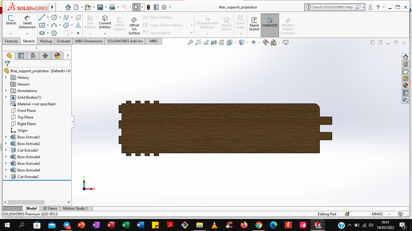
I remodeled the Just box by removing the sides except the one from the bottom. The small ones, are to allow the fixation of the support Both arms low.
The second box

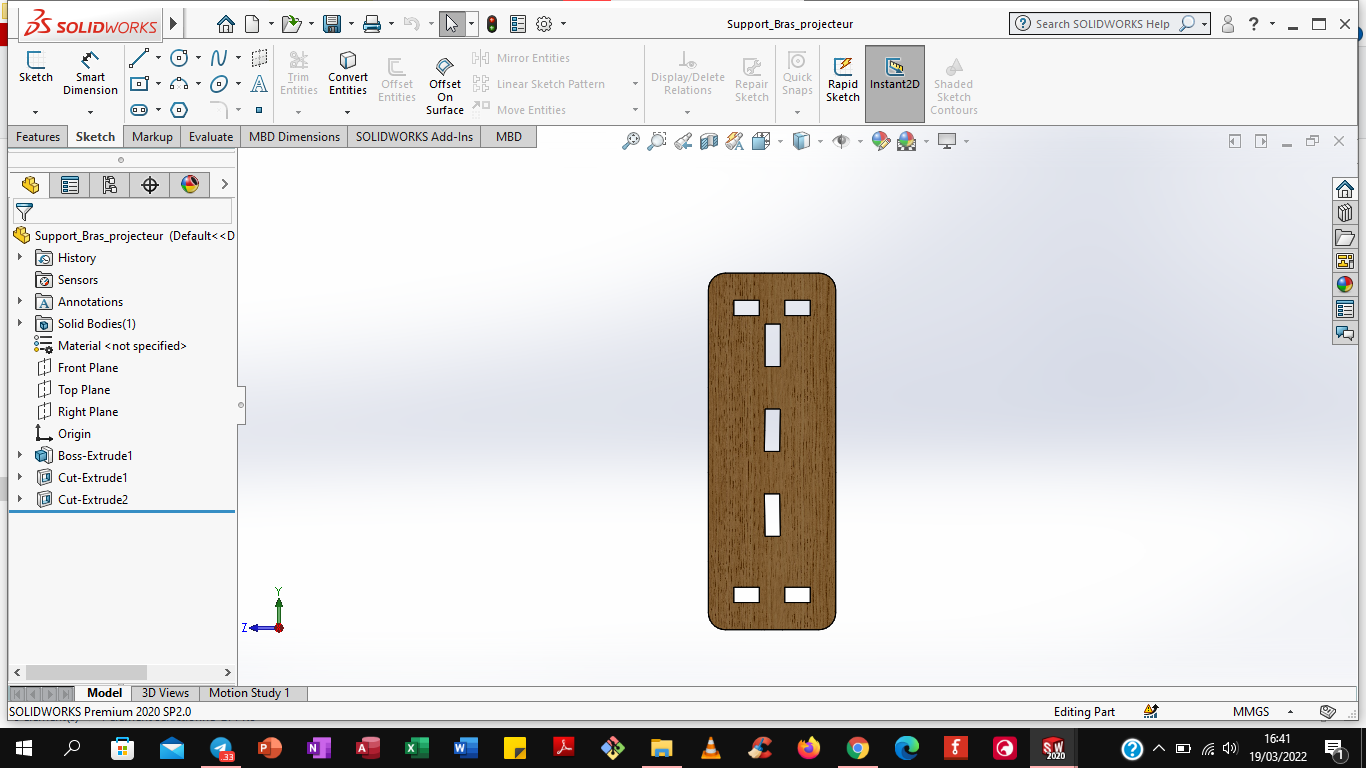
The modeling of the two low arms of the support. There are liaison Pivot with slippery arm. At the intersection we had placed a washer in each end.
the two low arms of the support
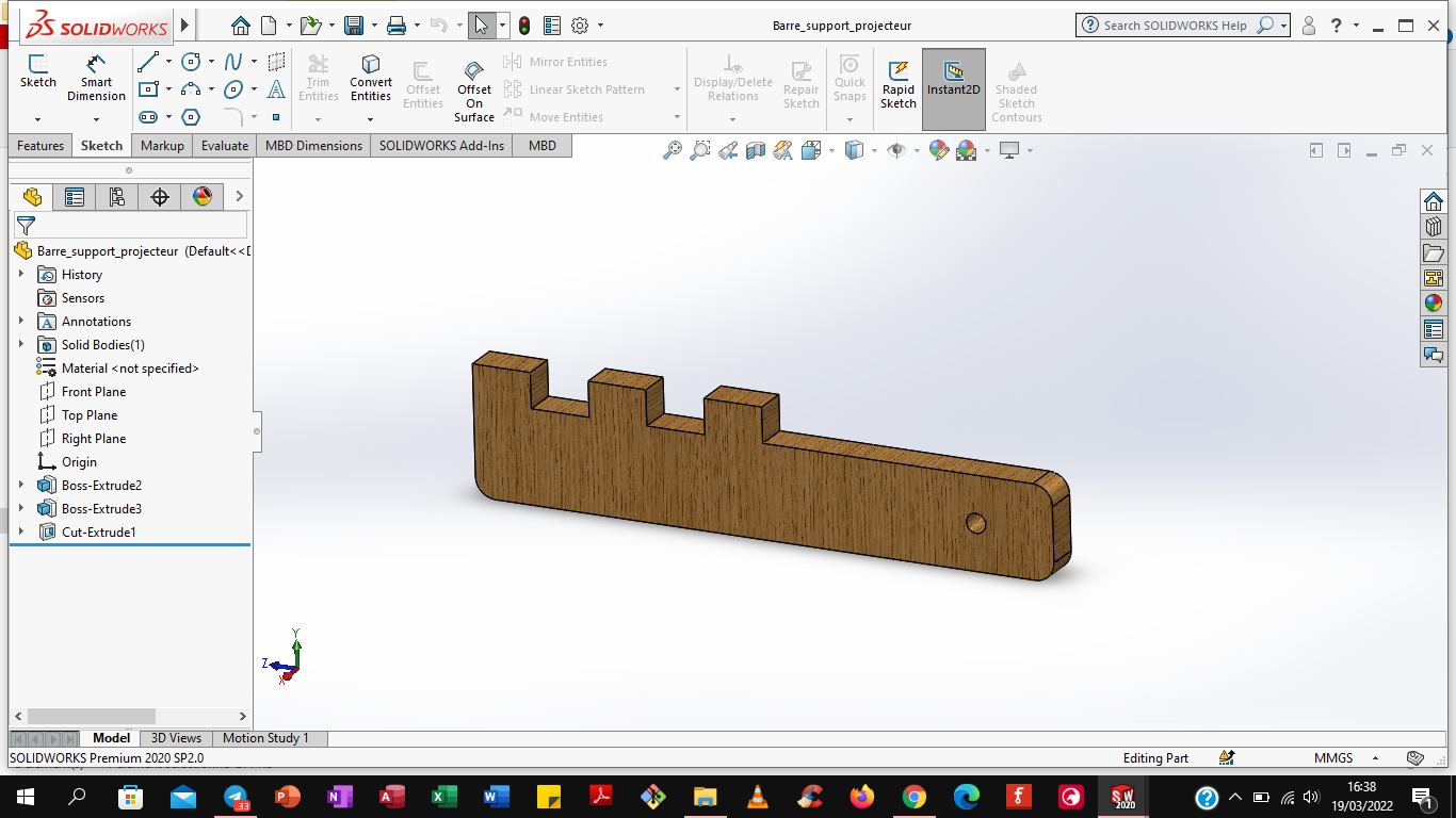
I have drawn the arm glissant. Sound role is to vary the height of the projector grace at the oblong hole.
the arm glissant
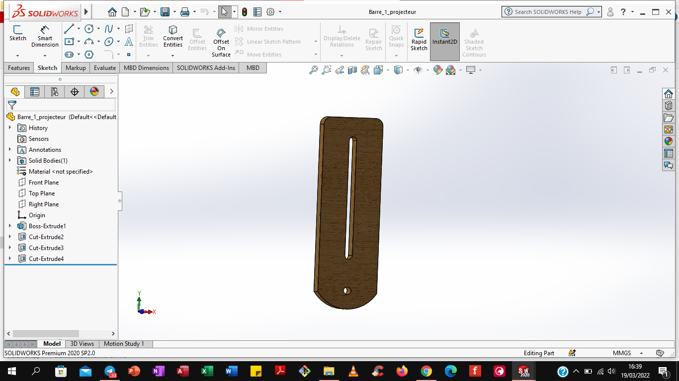
I have Modeled two arms that connect the arm slippery. They are fixed. They have two bolts with Nuts has an ear whose role is to keep fixed the height settle by the utilisateur.
the arm slippery
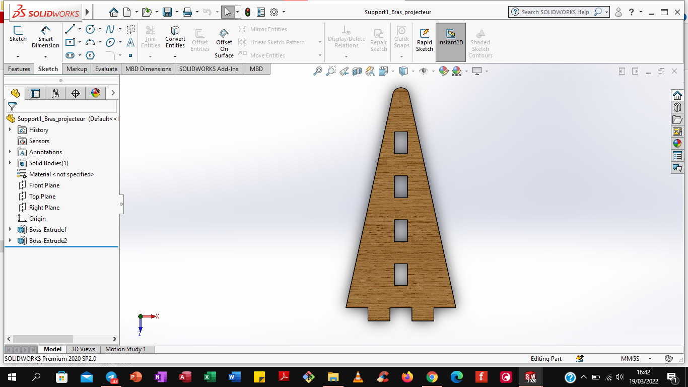
The design of the large support.il is fixed on the wall by three supports; the two arms are Fixed to the great support. That support keeps the whole set in height.
Big support
The parts that help the large support to stay fixed to the wall.This bracket keeps the large stand stuck on the wall.
Fixed support
These two supports are to support the strength of the support vertically.
Fixed worm
3. Subsequently I convert all ficyesterday that I modéread to dxf files.
To convert the file I placed it on its flat face. That is, placed has a view in 2D.
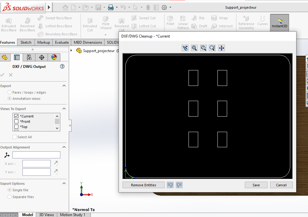
If you place it not well that is to say in 3D, the capture will not be good and the object would be printed in another form.
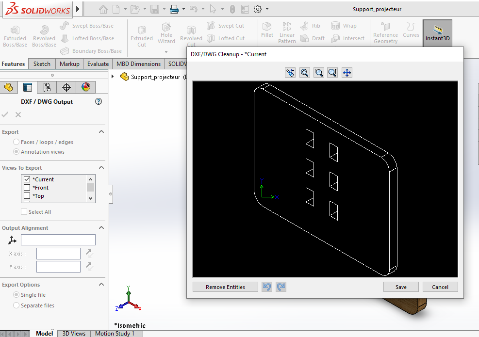
I have did this for all other objects.
Bracket Assembly

4. I have finished converting my files to dxf. I copied them to my personal key. Now I have to go on aspire a software that is on the shopbot pc. This software will allow me to place my objects on the shopbot cutting tray.
I open the software sucks, and in the first interface .I click on create new file..
The dimensions of the tray are set by default to 2440mm in length and 1220mm in width. The surface 00 is taken on the object (i.e. the Z0 that will be measured later. The quality of cutting resolution is Very high. and OK.
The blank page represents the surface of the shopbot tray. I will place my components on it and arrange them well to save my wood.
First we fixed our 18mm plywood on the tray. For the fastening parker screws and a portable drill were used for tightening; clamps were not used because there are parts of the wood that are deformed.
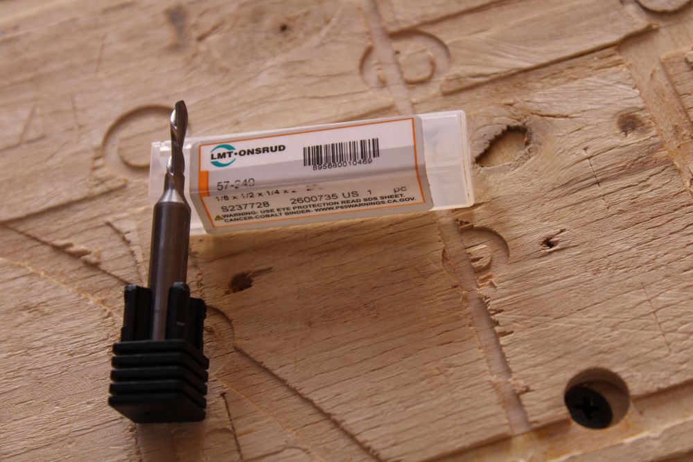
Then I changed the thin of 6mm than the to put a thin of 3mm.
To change The wick tool; during the loosening I do everything possible so that the thin does not fall, because its tip can be broken.
So for loosen the flat key must be placed First of all and the second place in such a way à have 30° (the shear force is much reduced). I grabbed the keys and then pinched lightly until you smell a good one desserrage manual. I removed the second key and I blocked thin with my doigt and the thin door then I have loose with the key, finally with the hands.
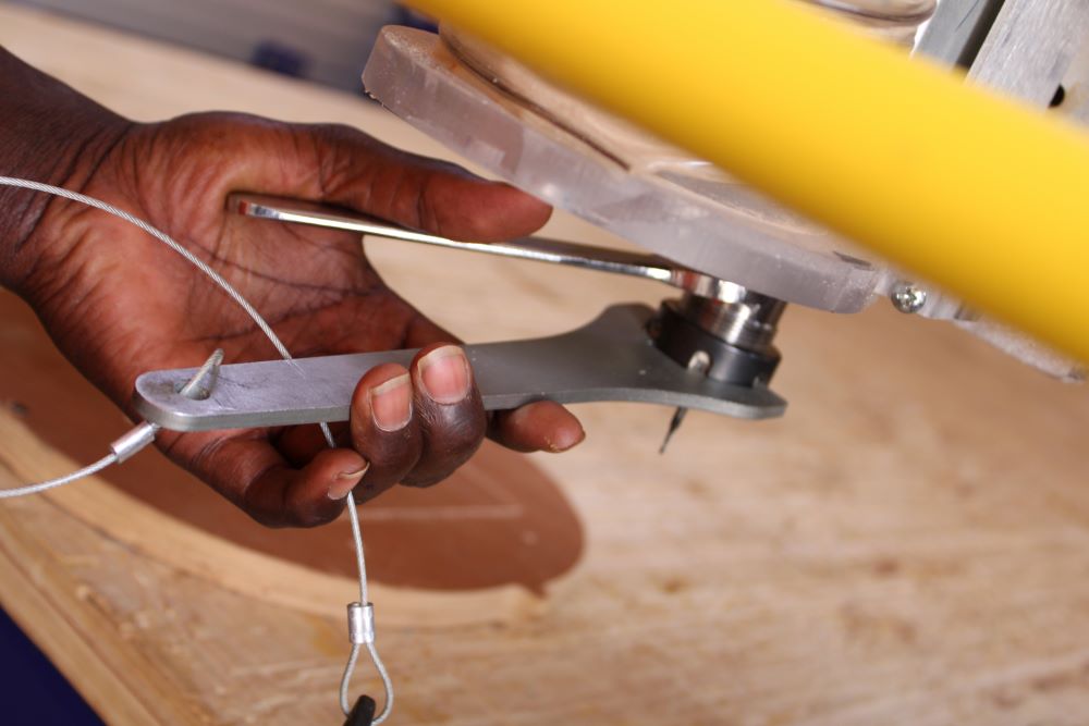
The wick tool didn't fall and then I grabbed her while loosening.
I changed by a tool End Mill of 3mm.I changed with the corresponding sheath.
I screwed the thin door and grabbed the thin one placed inside, screwed in manually so that the thin door grabbed the thin one and then used the keys to tighten the tightening.
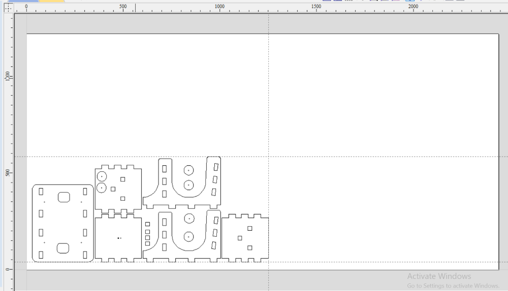
Finally I came back on aspire. Before we mounted the wood on the set and my Colleges MARE my ahead in the cup. To dispose of my coins so I used his aspire file as reference. In function of the layout of sound material I have willing mine also using the guides. To do this I opened his file aspire and I have a guide following the X axis and the other following the Y axis and I saved the measurements on my sheet. Then I opened my aspire file and placed the two guides with their respective dimensions. The space that remains I can exploit without problem. I left a distance of 25mm at all four ends of the wood to secure my tool.
The space already occupied by MARE
First of all, I exploited the voids that Existed in the surface of my college, I have eu placed two coins.
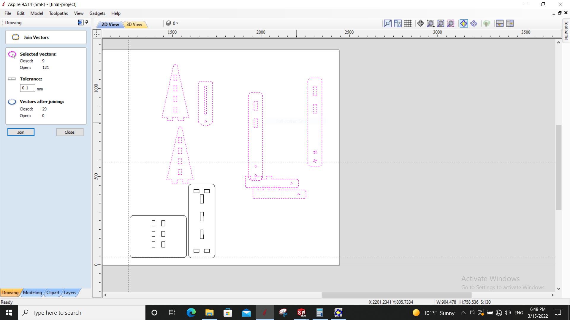
Second I placed the Other join and they were well disposed that he n'the had more space. After registered the room, Jai the ai selected then I Clicked on seal and I used 0.1mm seals.
The join
Between each object following X and Y there is a spacing of 10mm this is more than enough to place my Tabs. To place one object following another I click on the object and I click in Transform Valuables the function Set Selected Objects Size to see the position of the object or I Take two guides placed on the next object X and Y and I read their position. With these measurements I add the dimensions of the following object plus 10mm of separation. So I'm doing this for all the Other valuables.
The space what i have occupied

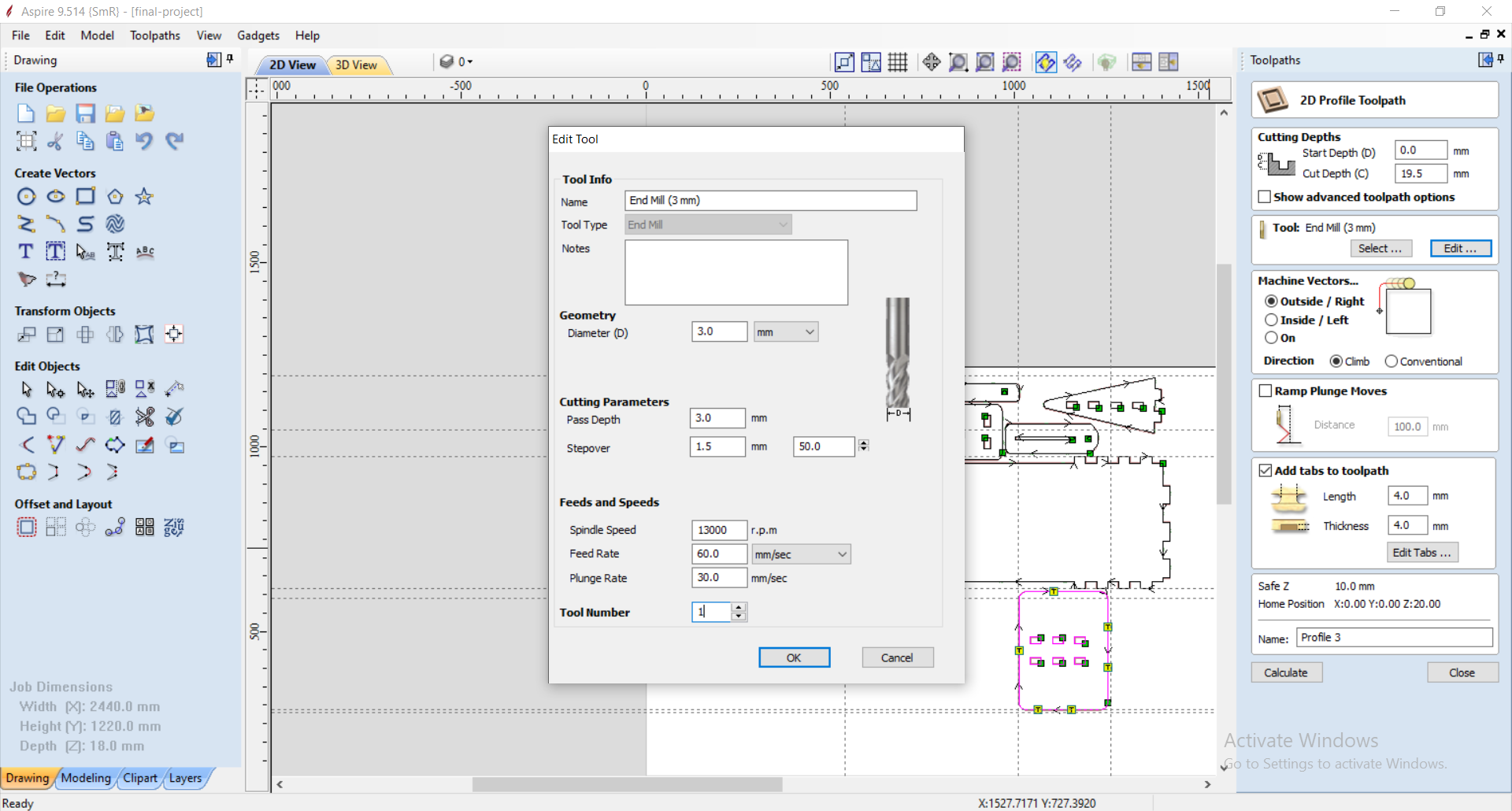
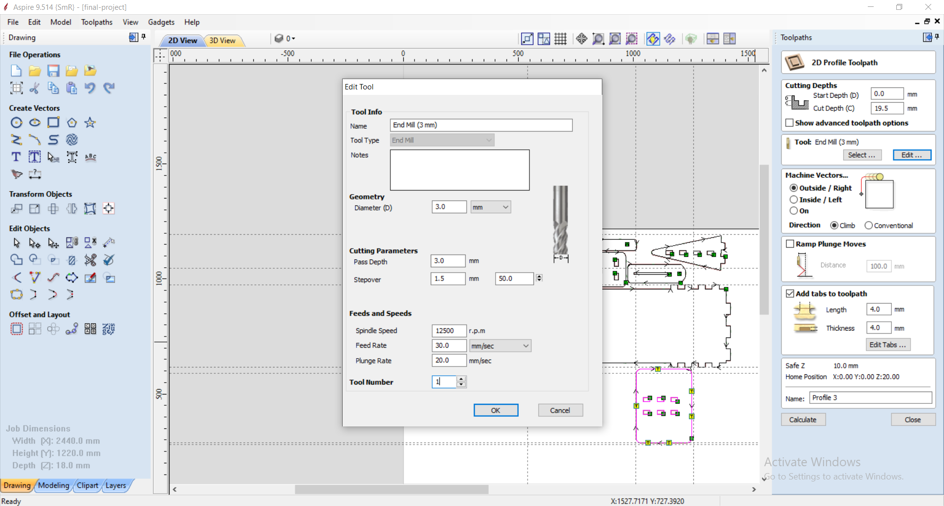
Third i went to Toolpath and configure the following parameters. I have fact one first cup with the object projector mount. I have Clicked on profile toolpath, this function is to cut wood. Then I mets the start depth a 00 is-i.e. the level à which the thin begins à cut, then the Cut depth has 19.5mm. L’thickness of my wood is 18mm, but the wood wasn't exactly flat, I have owing take the 19.5mm to compensate. Subsequently in Tool I choose the corresponding thin who is End Mill 3mm. The depth pass has 3mm and a speed of 13000rpm. a travel speed of 60mm/s and a travel speed following Z at 30mm/s. and Ok. I chose to cut à Theoutside of my room and it's the right option. Here same the Holes who are à Theinside are cut off automatically à Theinside always keeping the room Intact. I placed Tabs by clicking on the object then on add Tabs, then on Tabs edits. So the piece I ticked the parts that I want to put Tabs. On this piece I put 6 six Tabs and each Tabs measures 4mm in length and 4mm in width. Tabs are very important not only pas to keep the object still but to prevent wear of the tool. Finally I clicked on calculate, it generates the path that the thin will take blue color. Be pressed on 3D to see better. And I click on Save toolpath.et Ok.
The Cut Parameter
5.When I was done on aspire I now had to cut my design onto wood. So how to proceed?
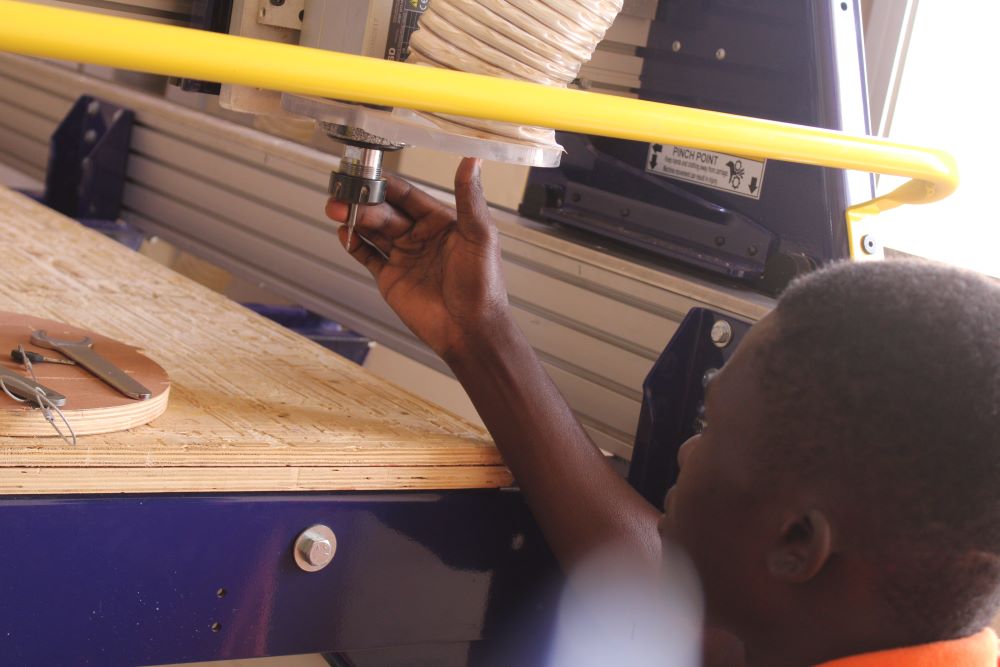
I have to work with the software that drives the shopbot machine. This is shopbot 3; first I start the shopbot machine with a turn button on its box. Then I press the reset button to switch on the motor power supply. Then I open the shopbot 3 software. It automatically detects the machine, due to the connection of its USB wire to the computer. On the interface of the software there are the displacement parameters of X, Y and Z. the software has two commands for the displacement also there the manual where you have to click on the arrows to do with the machine and the automatic part where Just click to make the machine move automatically.
But first let's do the manual, I click the Z arrow to lift the motor otherwise when moving it may hit something accidentally. I lift my head and then I move with the X arrow to put the machine in the middle. In this position I place my plywood on the shopbot board. This is 2400mm by 1200mm. After positioning I used Parker screws to screw the plywood against the plywood of the top, to prevent it from moving during cutting. No more fixing the plywood.
Then I close the manual function, I click on the XY0 function, the machine moves automatically to position itself at the coordinate (0,0) and I click on quit. Currently the machine has lost its Z0, so the next step is to help it find its way again.
Finally I click on the down arrow of X to move it backwards and on the right arrow of Y to move it to the right. The goal is to position the head of my wick on a flat surface of the plywood to be able to take the Z0. In order to position I place the sensor below the wick. Then I click on the automatic Z0. The one goes down a first time and when it touches the wick touches the sensor it stops and goes up then goes down a second time and goes up. I take the sensor and I put it in its place. The next step is to send the G-code generated by aspire.
I clicked on Cut part and then I chose my toolpath file and open. Then I clicked start. I pressed the start push button on the case to rotate the thin. Otherwise if you click directly on ok you will lose your thin. I made such a mistake. And finally I clicked Ok. The cutting was fast and it was well cut.
Control Brox

For more security I have decided to reduice the speed rotation at 12500trs / min and the speed of displacement a 30. In this second Cutting I chose all the objects that did not have summer cut. Then I have recorded and replace the old one.
New Cut Parameter
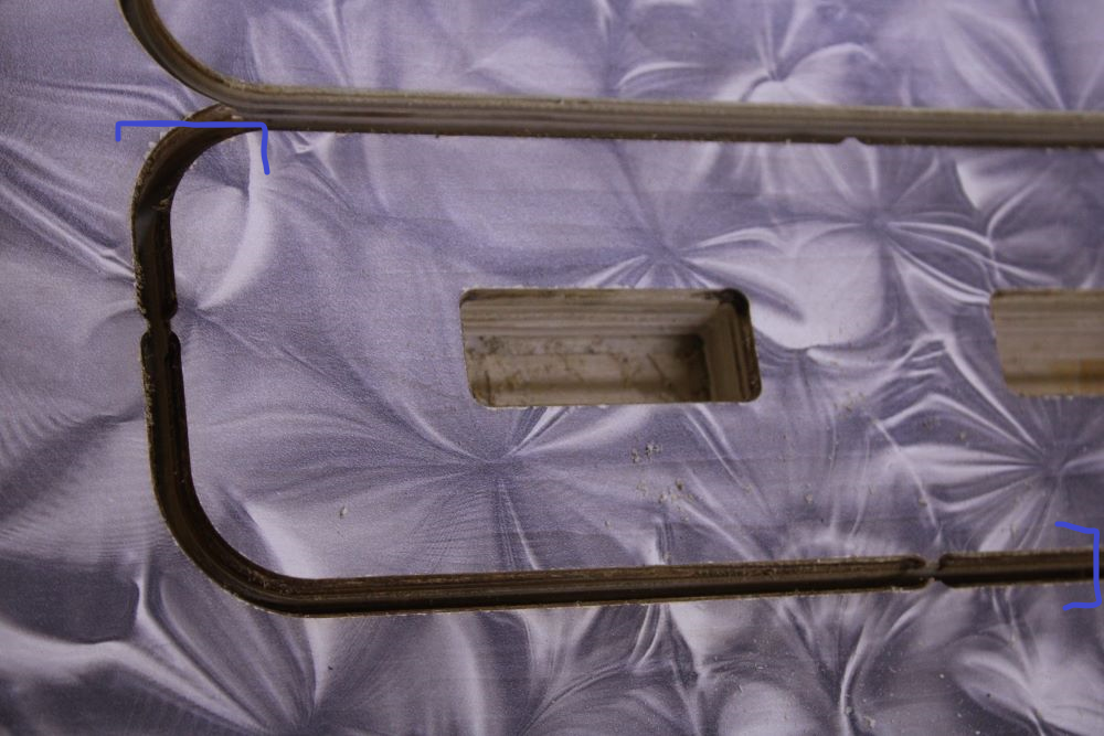
I started cutting afterwards. After cutting some edges of my pieces were blackened, then that during the cutting at the last pass there was smoke in some places. Indeed this is where the plywood was bulging. The major cause of this blackening is due to the short length of the wick I used. Soon I would use a longer wick. No more cutting now there is still the assembly.
The parts black
6.As for the assembly I applied a white glue (blond) in the walls and then parker screws to strengthen.
To facilitate the assembly, I used the edges where the wick was in contact, the one made a chamfer. I started by assembling the bracket and the bottom bracket, applied the glue as intended and screwed the screws using a portable drill. The surface of the plywood is smooth, I made a rubber-based washer to increase friction. In addition I used M12 bolts for tightening.
I then assembled the large support and arms that connect the slippery arm. Here I made a mistake because I cut some of the important wood. Actually when I finished the assembly and showed my coach Abu, I had put other wooden pucks to compensate for the space, but he told me that it was not three important. So I measured the space of the washers and cut them and it affected my remaining dimensions. Normally I had to measure the length I need it and cut the rest. To remedy this error, he advised me to place a washer in the middle of both arms and screwed. I modeled two washers and then cut with shopbot. After that I fixed the fixed bracket with the large stand. But it turns out that after this assembly I could not assemble the vertical fixed support. I disassembled it, assembled the vertical fixed support with the large support and then reassembled the fixed support.
The second phase is to fix my assembly to the walls measure as expected. We will use M8 screws and M10 female plugs. We used a total of 6 screws. First we pierced the fixed support with a 3mm wick, then we presented it on the wall to leave traces. These traces were used to drill the wall with a portable drill equipped with a 10mm concrete screw. After the drilling we screwed.
The observation:
a)The large stand was not totally flat.
b)When screwed for tightening, the screws sink into the wood.
The resolution:
a) I disassembled the bracket and then fixed it on the shopbot tray with screws. I placed iron corner 40x40mm² along the entire length of the wood and then screwed. This way the wood would remain flat.
b) I used simple washers placed between the screws and the wood. This increased the support surface of the screw.
c) I went back up everything and the result was better.
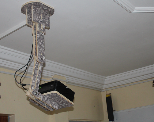
Finally my projector has a stand.
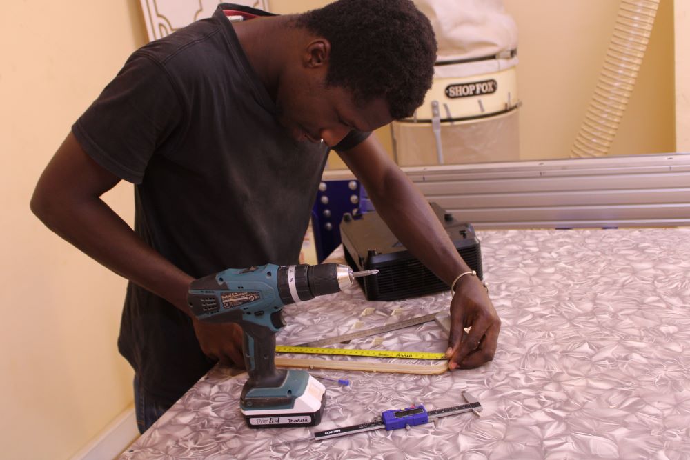
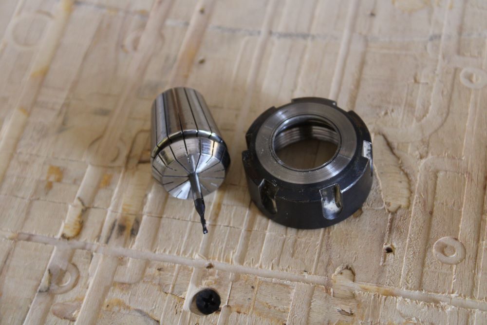
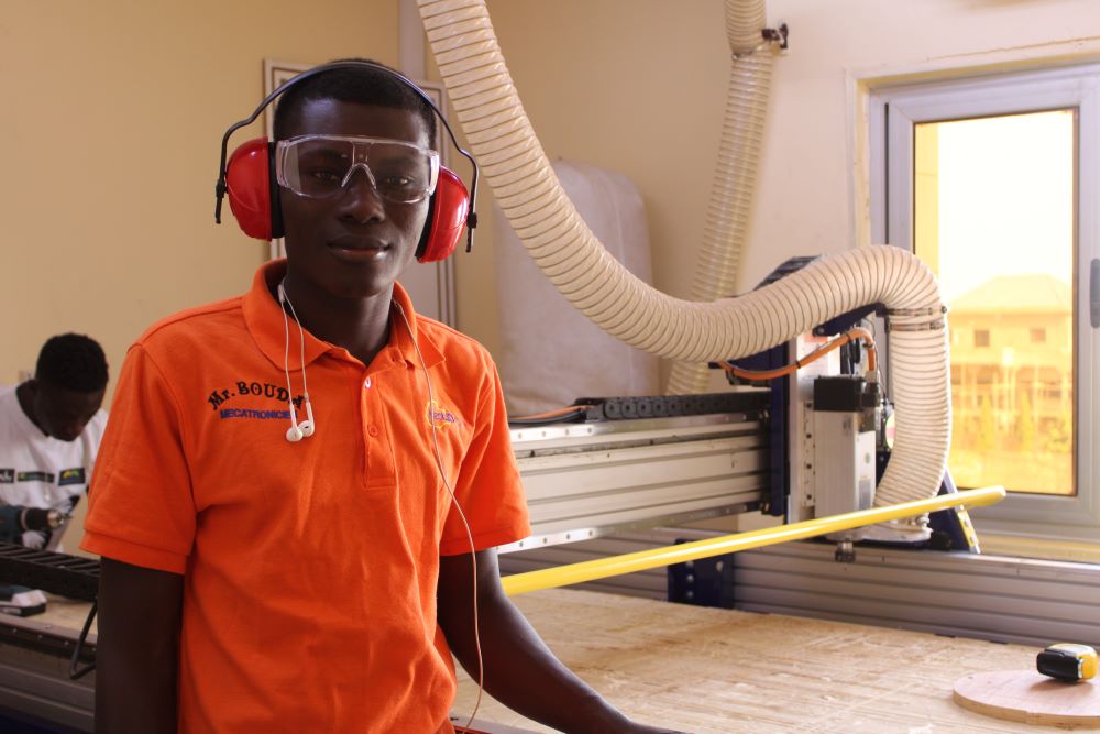
Me safe with EPI
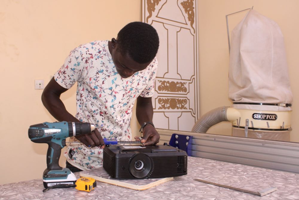
Me am taking the projector dimension
Me Freind SOMBE of Epilogue Laser Room