In this week 07 we worked in groups on the equipment of our laboratory to do tests. Then everyone would work individually. I am with two colleges.
For the group project
In our laboratory we are equipped with a multimeter, an oscilloscope and a frequency meter.
Let's use the multimeter to measure the continuity, voltage and current of a given circuit.
Our lab there is a circuit already all fact. That circuit for the microcontroller ATmega 328P-AU.on this circuit there and FTDI and AVRISP power pins.we used FTDI's and connected to a pc via le cable FTDI. Measure tension and current. Then on a tested the continuity of two sons so one was without continuity and the other with. It was very easy.
We fed and varied the voltage and current of our circuit.
We have a red LED circuit at our disposal. We used a GwInstek GPD-3303D voltage generator to power our circuit. We varied the voltage from 2v to 3v and we saw the brightness vary depending on the voltage. The more the voltage is increased, the more the brightness increases. But when we increase the current nothing happens, on the other hand the current varies according to the voltage. We almost lost our leds, that is to say the grilled. We varied the voltage up to 5v and a second later we saw smoked. So we remove it at the same time to avoid losing all. But when we turned on all the LEDs were rallumés.si we did one more second we would be able to recover them.
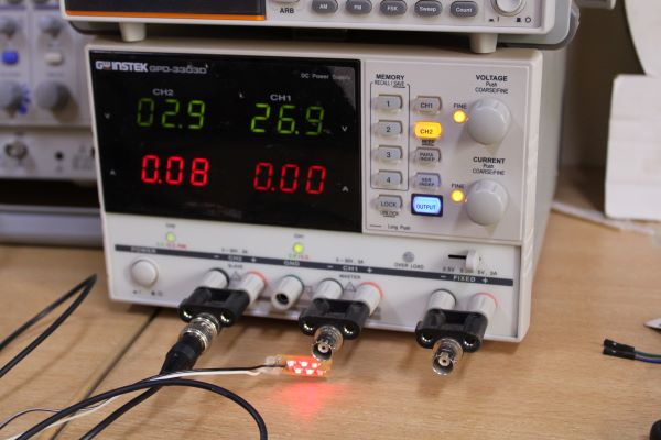
GwInstek GPD-3303D DC Supply
The frequency meter to measure the frequency of the atmega328P-AU circuit.
The circuit has a Crystal by which the microcontroller takes its clock. It is a Crystal 20MHz smd has three pins. We have the GwInstek GDS-1152A-U oscilloscope device. Nous had difficulty measuring the frequency of the crystal because we do not know how to handle this device. So we watched tutorials on YouTube and then tried again. We were able to measure the frequency between one of the crystal pins and the GND and the other too. With the buttons of the frequency meter we put the division time at 500 microseconds. The first measurement gave 7.984MHz and the second 8.065MHz or 32ns as the period.
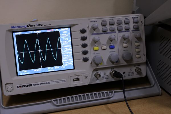
GwInstek GDS-1152A-U digital oscilloscope
In this week of electronic design I go individual
In my individual mission here is what I had to do.
1-First install the Eagle software
2-Then I will do some research on the component attiny44
3-In addition I will draw its electronic circuit on the software
4-I will solder the components and check the board to work.
5-Finally I will use Arduino as an ISP to upload a blink code.
In the KeoLAB lab I take care of the electronics section; so I have notions in electronic.je would say that for this mission I would take a day to accomplish it.For the layman this link would be very useful
The component I will study this week is attiny44.
Research on the attiny44 component
I read the datasheet of attiny44 on this link be very useful to you. Read the role part of the pins, locate the pins of the Crystal and FTDI and the pins of AVRISP.
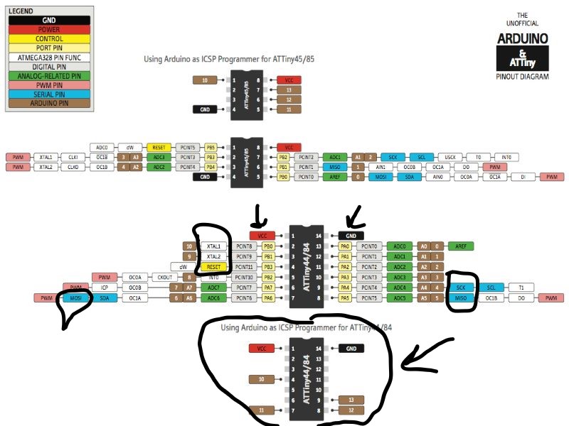
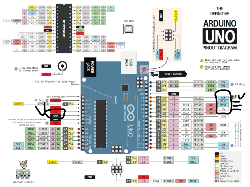
Pinout attiny44
Pinout Arduino ATmega328
Electronic circuit design with eagle software
After the installation of the software I opened it. D'abor I went on internet download the bookshop agob of eagle. Then I got it dézippé and I copied the file, go In the storage C In the EAGLE file 7.7.0 in the folder lbr and I paste the fab file. I am Leavesie in eagle I click on the part add then use I choose Fab and open to add components who is there was.
After intégration I used the Fourth (4) Arrows to facilitate la navigation in the add. In fact in the component search bar of add it's hard to find exactly the component that your want, you Can trapper the name of the component yet it is not writing of the same manner so you don't Could not the coir. It's for this I use the Arrows, en more it allows me to see the shape of the component if it is a smd or it is a component with legs. I choose the fab components I need for my circuit. If I have any doubts about the brochure paws I tape the name of the component and I compare the numbers names of pins if they are the Same then I have the right component.
I now have to the connected, I connects them with the function Wire. You need to know that the arrangement of the components here does not affect the circuit. After the bindings of the components I click on Generate/switch to board for generate your electronic circuit. Click on yes. You Must move your components in the white box. Now I'm going to generate a circuit road. To do it there are two method either you Do manually with the command Route for tgo outthatr and Ripup to remove the trace or manner automatic with the command Autorouter.
But I have pReferred do it manually because with the Autorouter it can happen that the circuit is double-sided. Manually too you Can see your level of strategy. After all this I will generate my circuit as an image and then use it in another software, which is aspired (on Uses the image for generate a file that my Machine Modela MDX-50 Recognizes).
Then I click on layer setting click sur None ticks the color top and dimension. Then on Generates the image by clicking on bethe then on export then on image then I car monochrome, resolution a 2000 clicks on browser afterur save the file.

Eagle interface
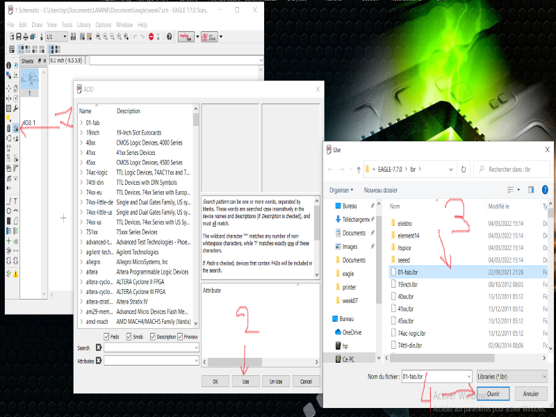
Add the library
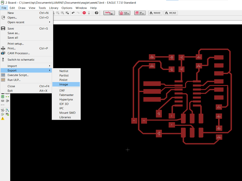
Export circuit to image
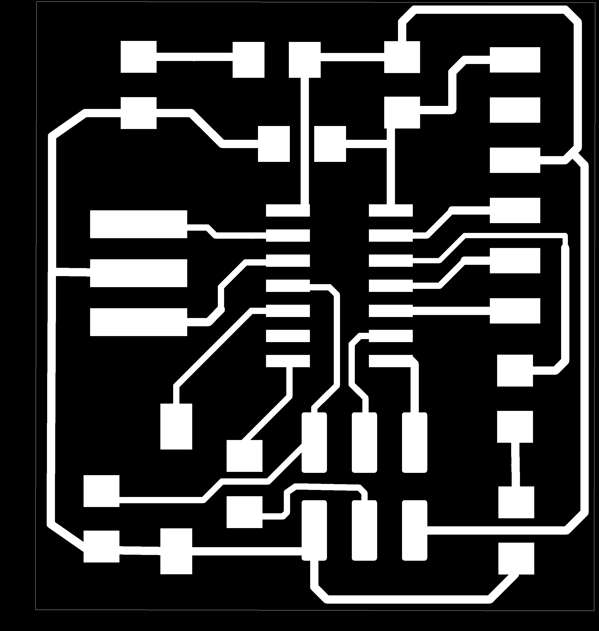
Circuit picture

Circuit board picture
Electronic circuit design with eagle software.For the circuit project here are the components:
Attiny44 (UC ATTI SOIC14 in eagle) x1
Crystal 20MHz (XTAL_RE in eagle) x1
LED (LED LEDF in eagle) x2
Pusher (SW OMRON SWITCH in eagle) x1
Capacitor (CAP in eagle) 01uF x1 ; 10uF x1
Resistance (R R1206FAB in eagle) 100r x2 ; 0R x2
Connection FTDI (CONN 0 dans eagle) x1
Connection ISP (CONN CON 2X03SMD dans eagle) x1
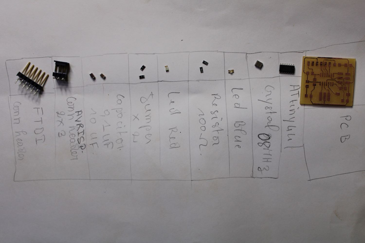
List of components
Soldering of components
The material that facilitated the welding

Smoke extractor
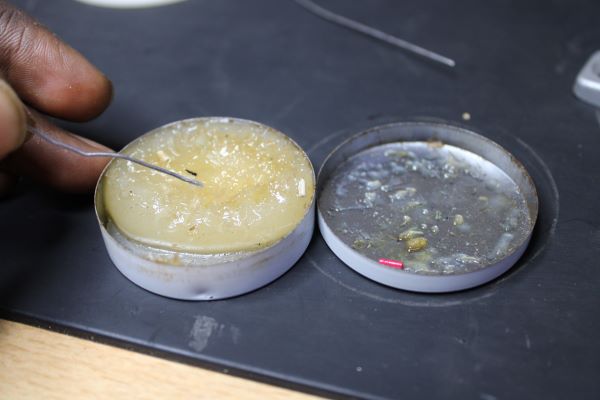
The PASTE

Analogous welding station
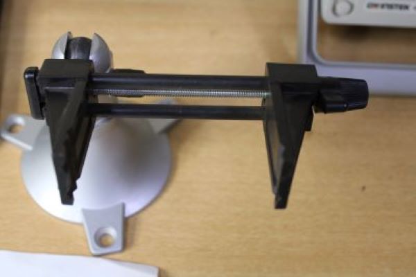
To catch the pcb
After the design of the electronic circuit , i.e. the finished PCB, we move on to welding the components on the PCB. We already had the components in hand, so no need to look for them. When I prayed my PCB after realization I found that in some part of the circuit there were, if we can burrs or copper not removed, I used my cutter and make a passage on the entire surface of the PCB.
Cela made it possible to scrape the copper that was lying around. So let's go to the welding, I used a fan to suck the smoked tin. Then PASTE, it is a tin cream that facilitates welding and increases the quality of soudure.je specifies that it also works as a heat multiplier and reduces energy consumption. I used an analogous welding station i.e. the temperature is adjustable. Sa temperature I set it to 280 degrees. The first of the components I welded was the attiny44 since it had many legs and small than the others.
To weld I place the iron on the welded part, then I bathe my tin in the PASTE and finally I put it in contact with the soldering iron and copper at the same time. After the deposit of the tin I then place the paw of the composant and I place the do a welded. The tin melts and grabs the paw. I used this method to weld all the components. Afterwards I check if my weld is well taken.
To check if my component is well welded I do the continuity test with my multimeter. To do so I place on the pin of the component one of the wires of the multimeter and the other on the copper that connects it. The multimeter will inform me by an audible signal if there is continuity. Otherwise there is no continuity. Finally the welds were good and there was aesthetics, i.e. no tin overload and the placement of the components are almost all straight.
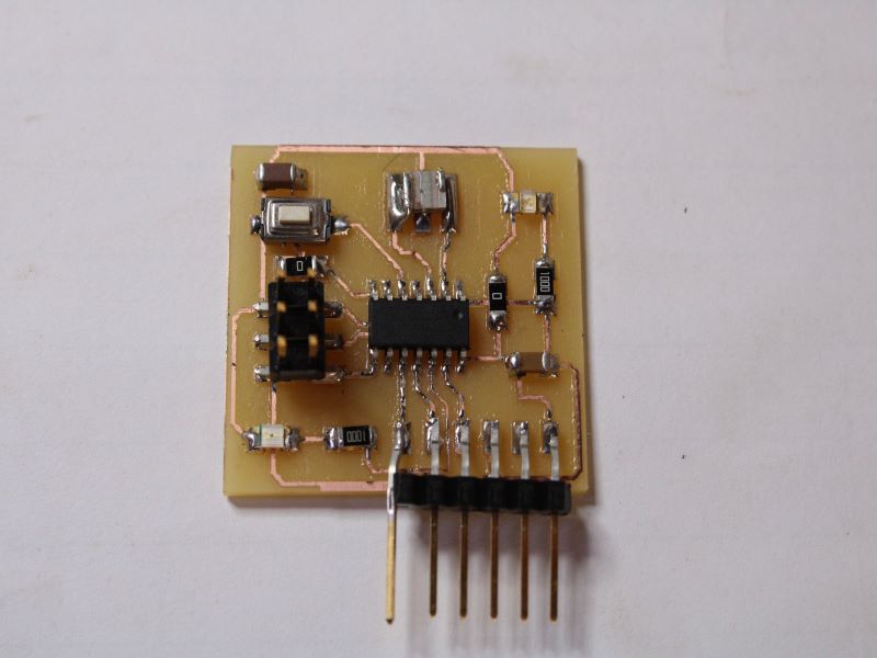
Soldered circuit
After the design of the electronic circuit
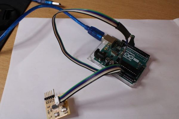
How to use Arduino to upload a code to ATtiny44
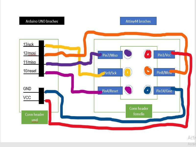
1/ Reaction of an ISP cable for connection between the Arduino and the attiny44 board. I used a Female Conn header 2*3.
Arduino ===> one Attiny44
GND ===> GND or 14-pin
VCC ===> VCC or 1-pin
11 ===>MOSI or pin 7
12 ===>MISO or pin 8
13 ===>SCK or pin 9
10 ===>RESET or pin 4
Design of the AVRISP cable for downloading the code from Arduino UNO to attiny44. The connection between the two components aims to use the Arduino as a bridge i.e. ISP and it is the cable that connects them. One end of the cable uses the Arduino pins and the other the attiny44 pins. On the cable we will use six (06) connectors (flat cable), six (06) Conn header smd and a conn header female 2x3. First I passed the 06 connectors in the female Conn header, I pressed the Conn to make a crimp connection, then I used a hammer tap to have a rigid connection. I connected the respective pins for Arduino 13(sck), 12(mosi), 11(miso), 10(reset), vcc(5v) and gnd with attiny44 pin 9(sck), pin08 (mosi), pin07(miso), pin04(reset), pin01(5v) and pin14(gnd).
Trace circuit
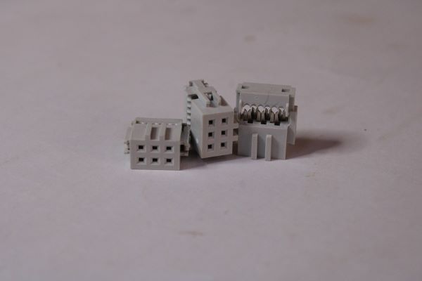
female Conn header 2x3

Conn header smd
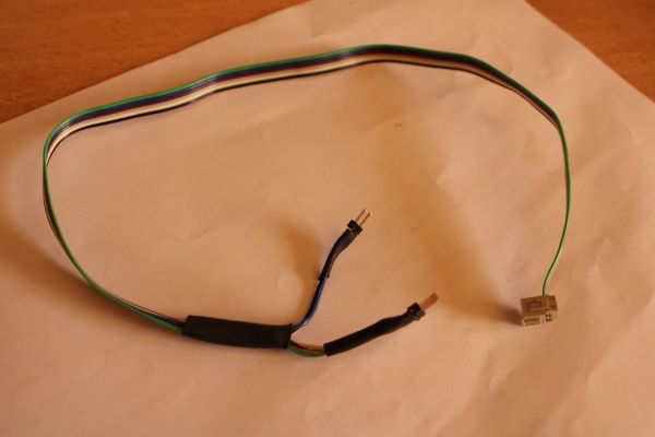
Cable