3D scanning and printing - Group Assignment
Group assignment:
The goal of this weeks group assignment was to learn more about the 3D printers at our local FabLab and to characterize their properties and limits.
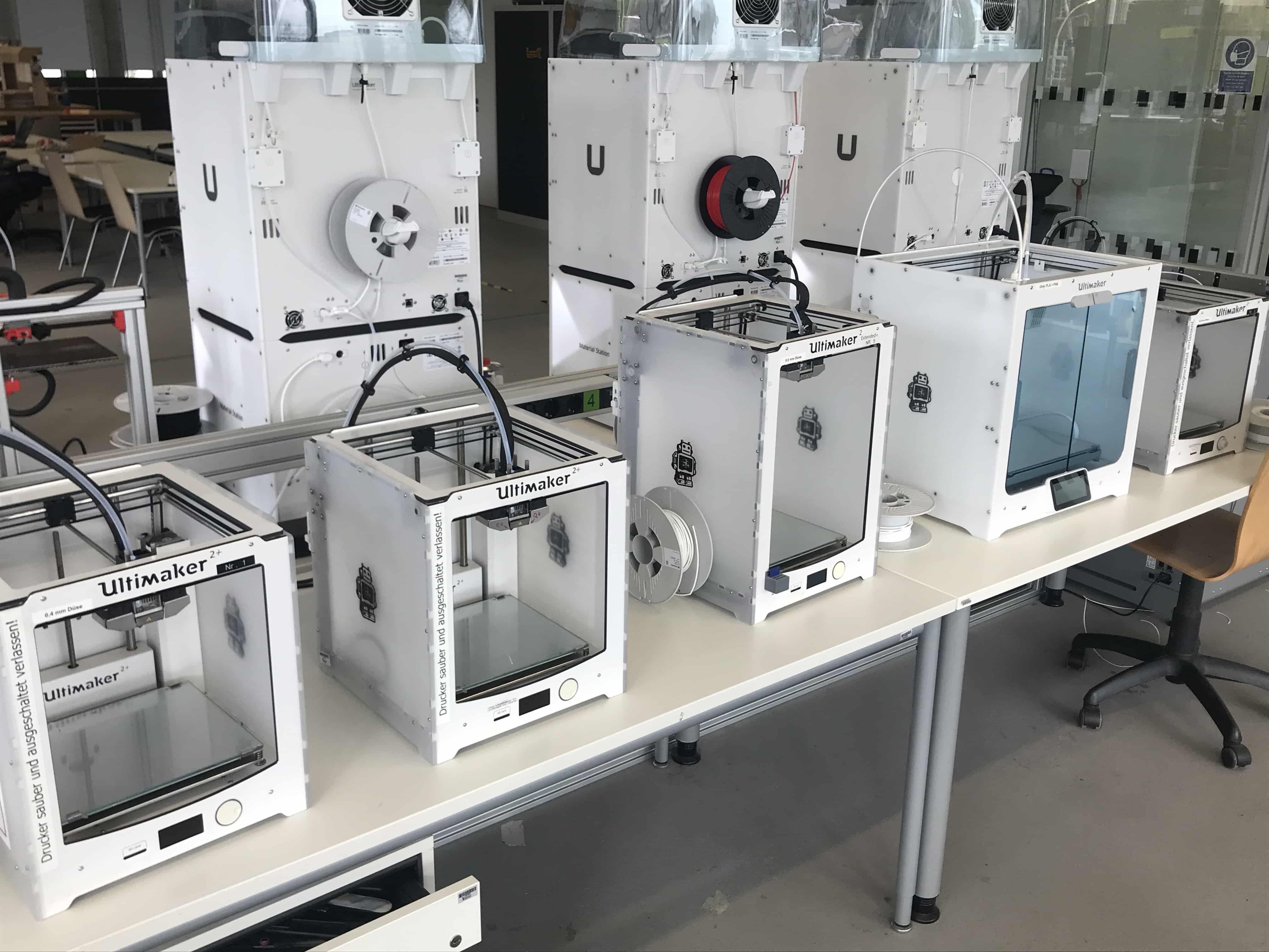
In the FabLab in Kamp-Lintfort (Germany) we mainly use the Ultimaker S5 3D printers:
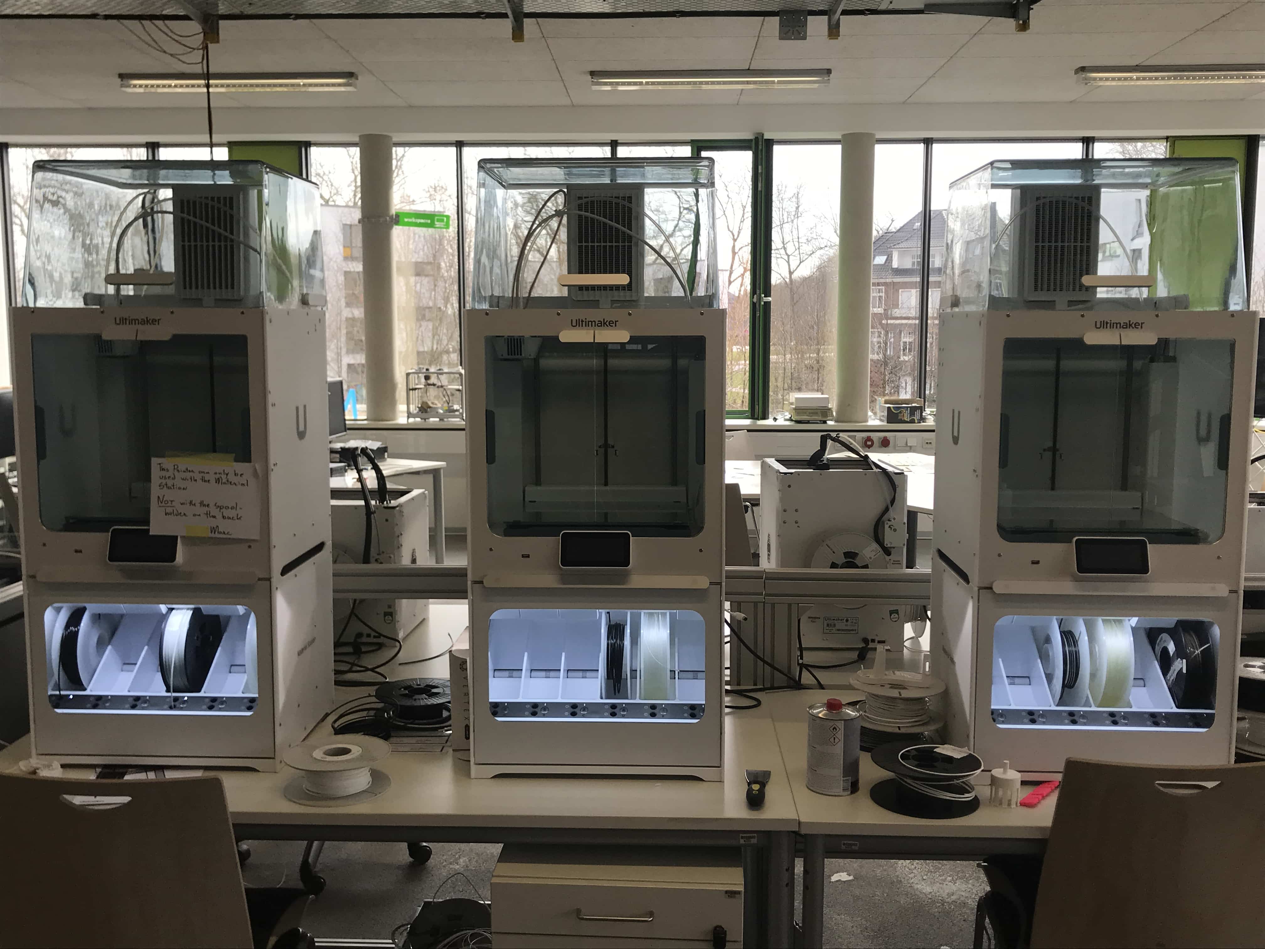 The printers we used for the group assignment ^
Testing the design rules:
The design rules to test with the Ultimaker S5:
Pictures are taken from FabAcademy website.
 1. Angle
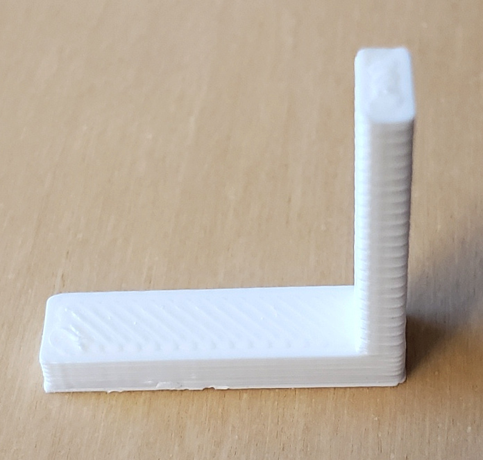 2. Anisotropy
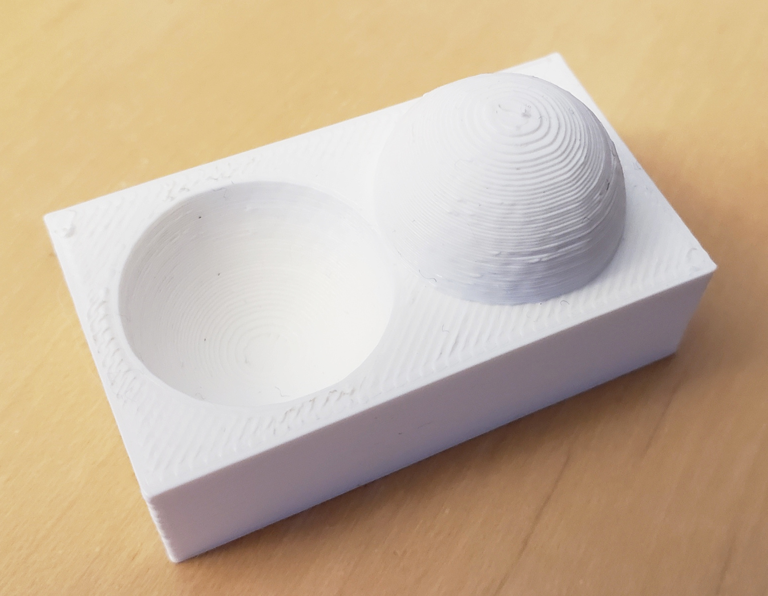 3. Surface finish
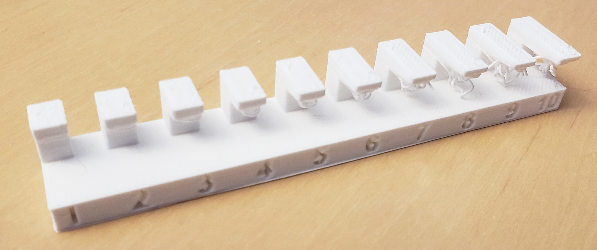 4. Overhang
 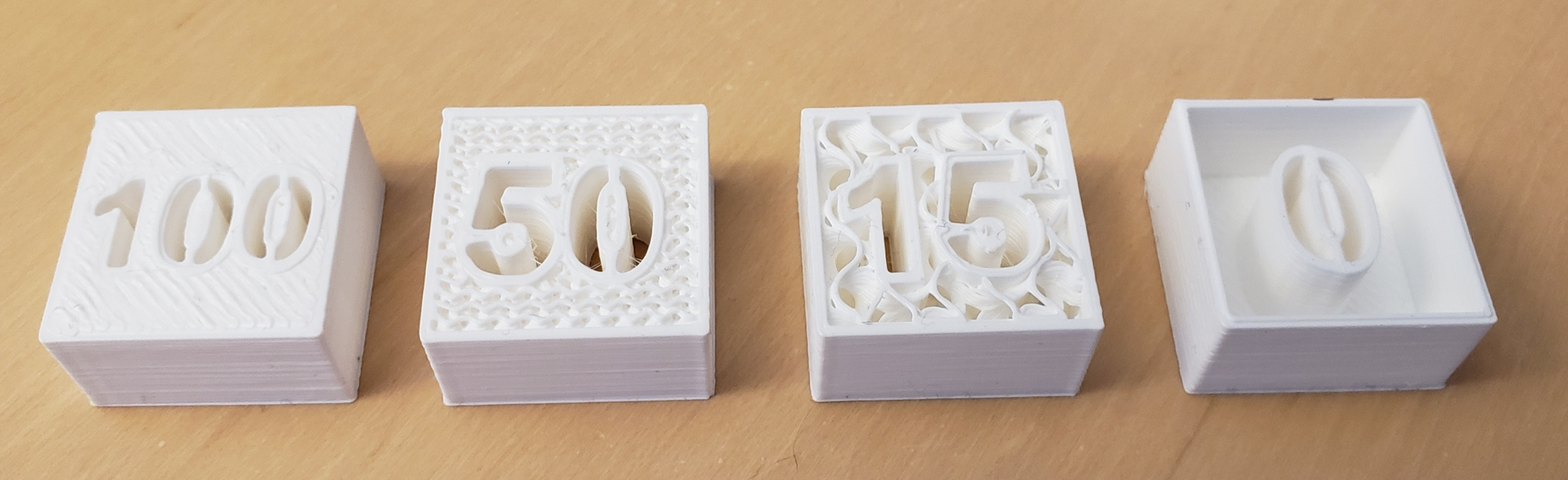 5. Infill
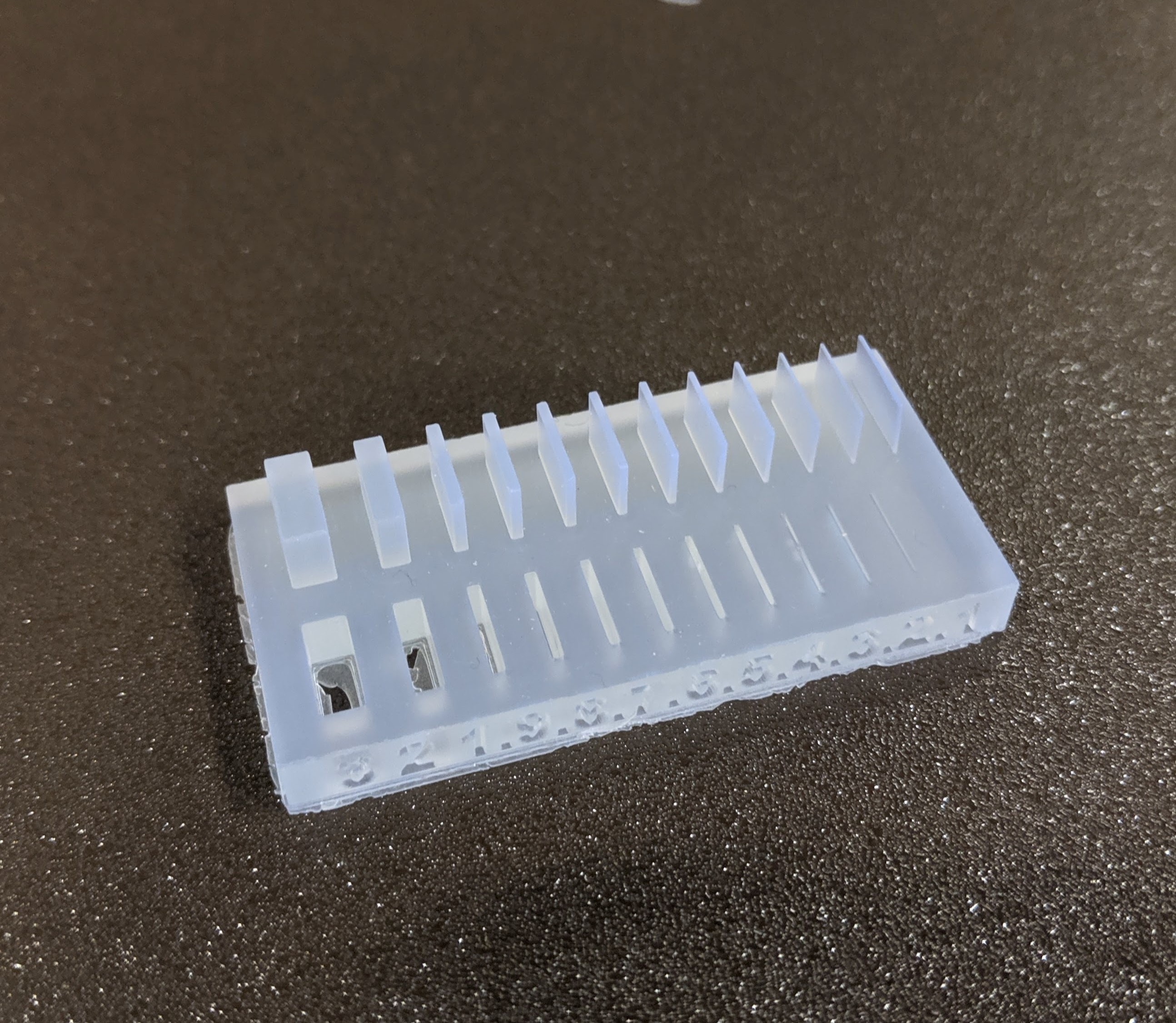 6. Wall thickness
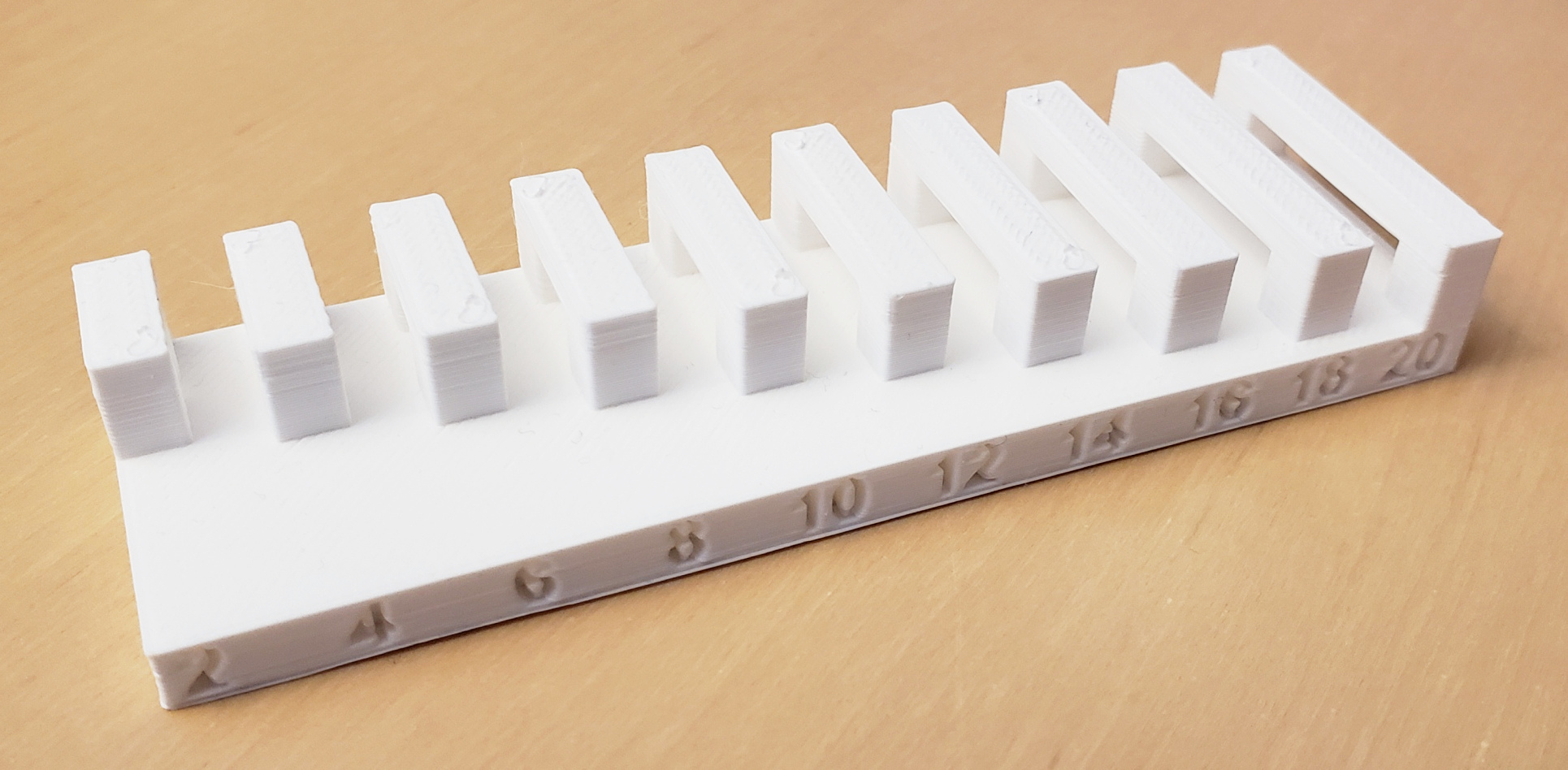 7. Bridging
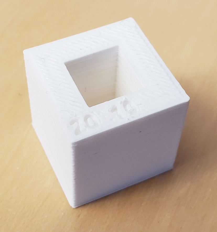 9. Dimensions
Overhang, Angle, Bridging, Surface finish
We found a few "All in One Printer Tests" on Thingiverse, that were perfect for the assignment and tested multiple design rules in one go. We downloaded All In One 3D Printer test
by majda107 November 19, 2017 and All in One 30 Minute 3D Printer torture test
by heqe95 March 10, 2020
Both files were imported in Cura and prepared for printing (without support):
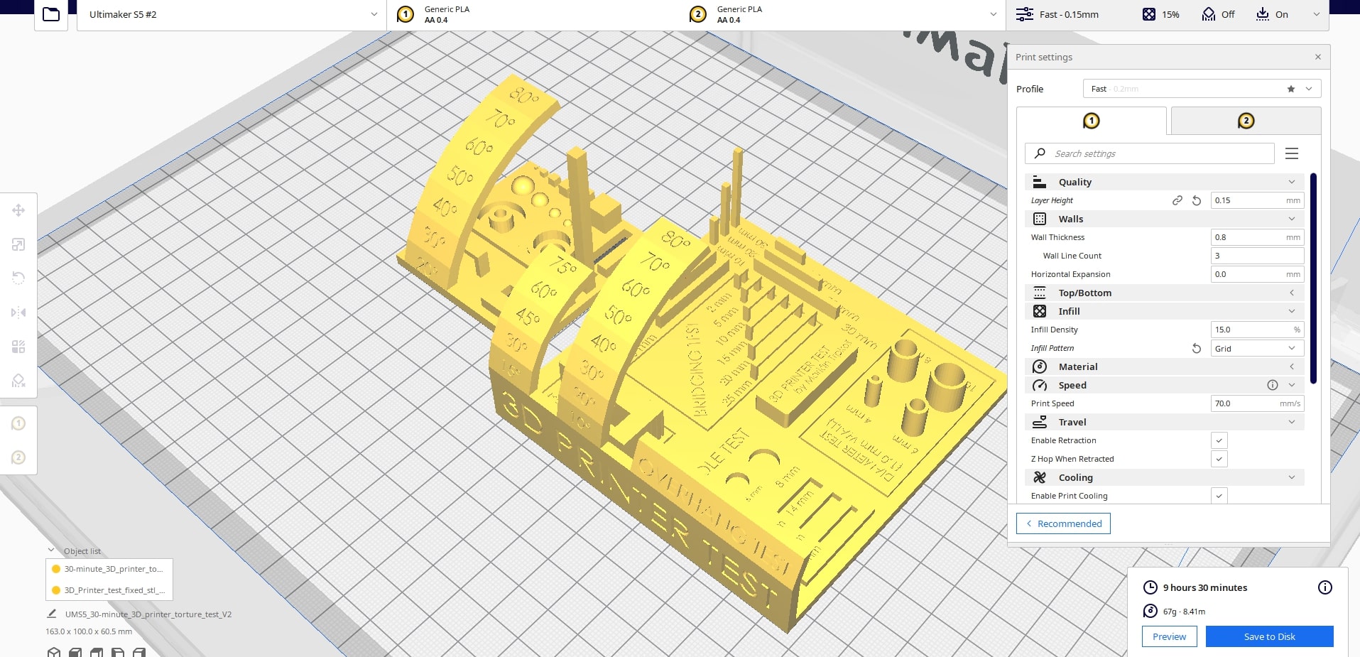 The all in one tests + settings (save to removable drive and start the print)
9 hours later, the prints came out like this:
.jpg) 1. Small test
1. Small test.jpg) 2. Small test
2. Small test.jpg) 3. Large test
3. Large test.jpg) 4. Large test
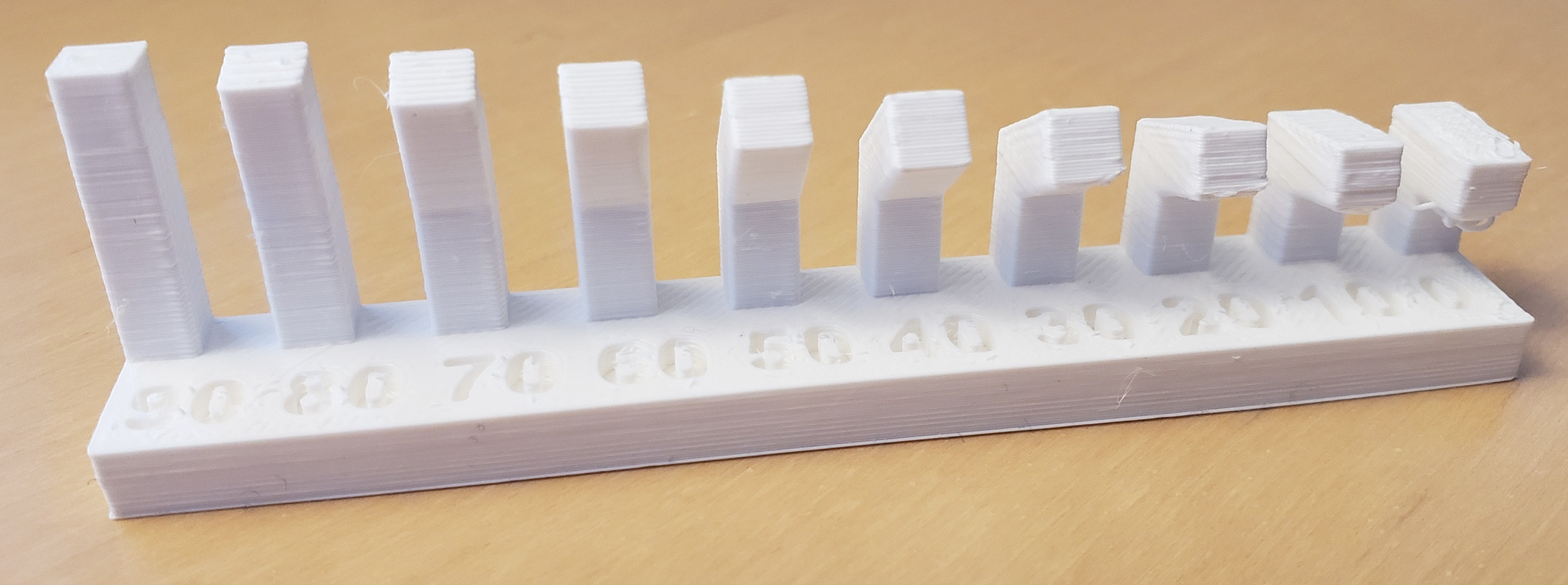
4. Large test- Supports should be used for 45° angles and above. (For the curves with a smaller radius, stringing occured earlier than for those with a higher radius (smallest radius start of stringing: 45° | medium radius: 50° | largest radius: 60°))
- Bridging over a distance longer than 5mm will leave strings.
- Printing spheres smaller than 1mm will make them look more and more like cylinders the smaller you get (same thing goes for cubes).
- Extra: Printing text on the x-y-plane is a lot more inaccurate than on the other two planes and the text needs to be a lot bigger to be visible (see image 1 and 3)
Wall thickness, Dimensions, Anisotropy
To test the wall thickness, dimensions and anisotropy, we used the tst models provided on the Fab Academy website. As soon as you slice and go into preview mode, you can already see that the thinner walls from 0,3mm to 0,1mm won't print. This is very likely caused by the nozzle of the S5 being 0,4 mm.
We also used a support blocker (explanation below) to print the anisotropy test with 100% infill density.
.png)
.png)
.jpg) The slimmest gap that was actually clear is the 0,6mm gap.
The slimmest gap that was actually clear is the 0,6mm gap..jpg)
.jpg) The cube was supposed to be 20mm wide on the outside and the hole should have been 10mm.
The cube was supposed to be 20mm wide on the outside and the hole should have been 10mm..jpg) The cube is actually 18mm on the outside.
The cube is actually 18mm on the outside..jpg) And the hole is actually 8mm. 2mm got lost for both dimensions, mind this when designing your models!
And the hole is actually 8mm. 2mm got lost for both dimensions, mind this when designing your models! 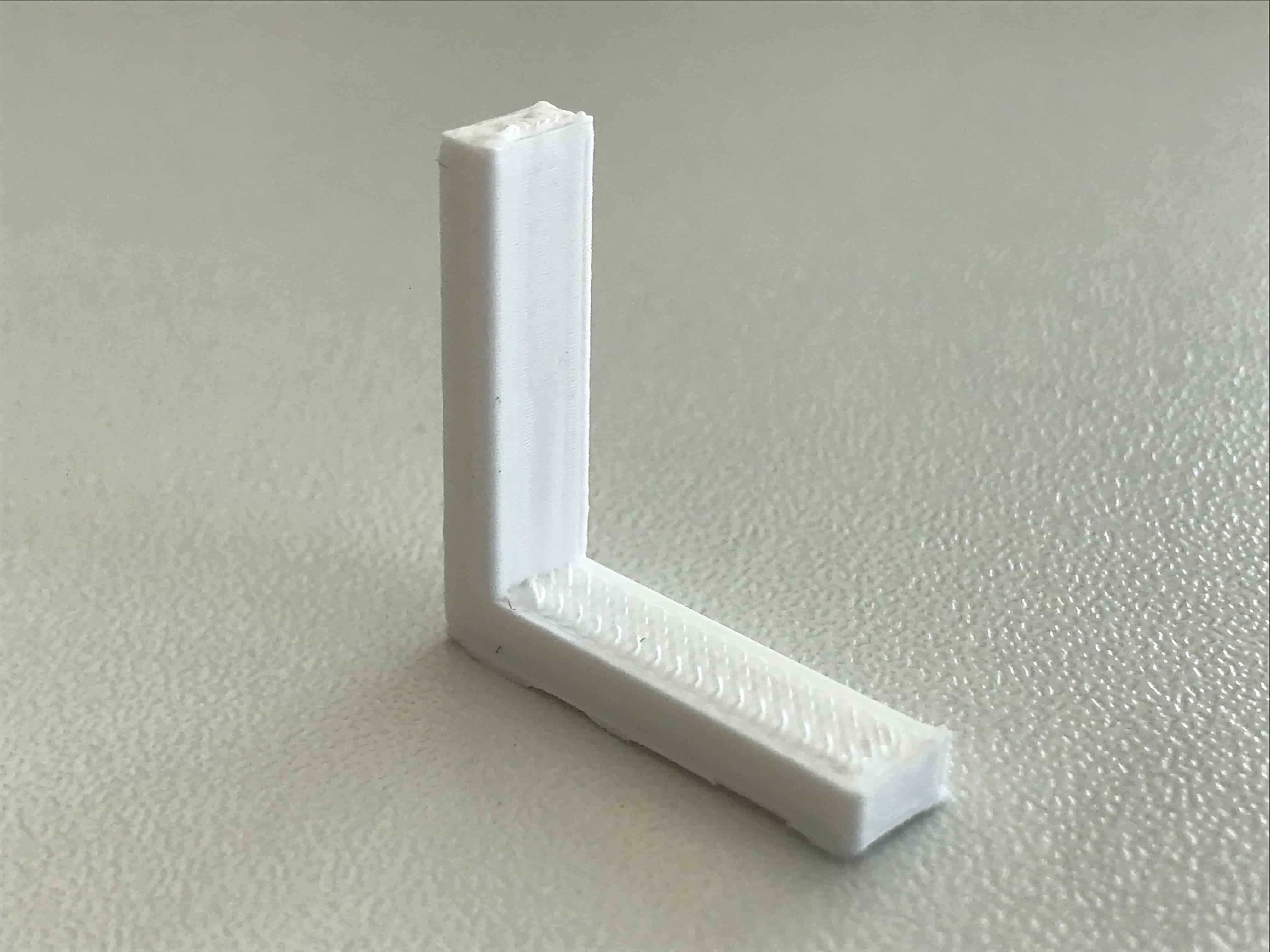 In theory, this model should break along the x-y-plane, because that is where the printer adds layers.
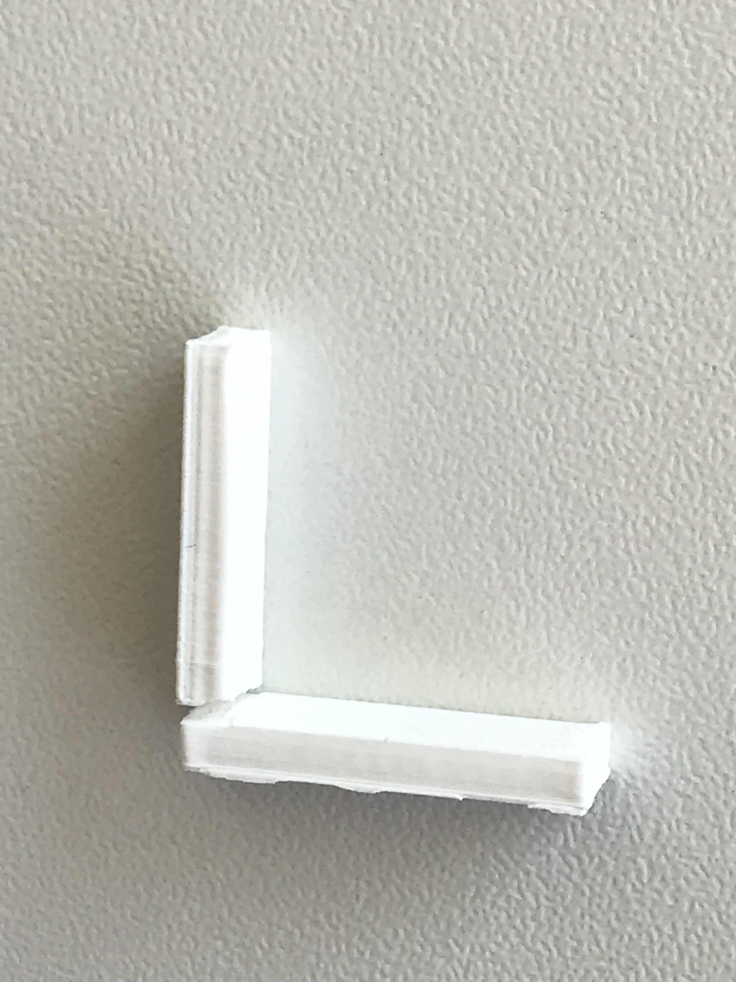 And it did!
Infill percentage & infill style
We used two more models from Thingiverse for these tests: Infill Percentage 3D Printing Terminology Demo
by ChuckWheat March 06, 2019 and Cura Infill Patterns Display Models
by Lyl3 January 21, 2021
These prints are a bit special for the following two reasons: Different settings are needed for different areas of the same object and there should be no top layer, so one can see the infill. We followed this tutorial to achieve the desired settings.
If you don't want to watch the video, these are the steps:
- Set up a new project in Ultimaker Cura with the default settings (Printer: S5)
- Choose a layer height to your liking (0,1 - 0,2)
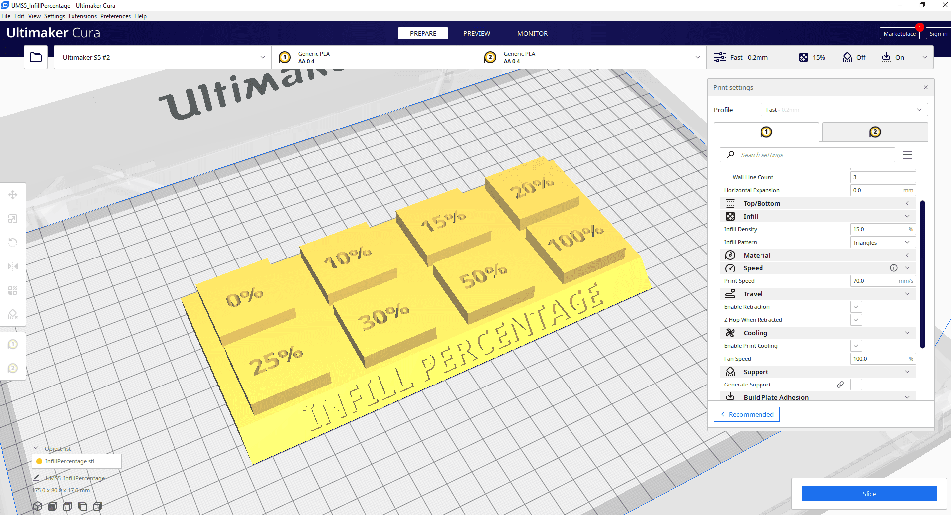
- Choose a default 20% infill (This will apply to the base of the model)
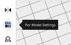
- In the left menu of Cura, 1. Select the Support Blocker, 2. Click somewhere on your model, 3. Resize the Support Blocker to fit the needed area.
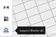 1.
1..jpg) 2.
2..jpg) 3.
3.- 1. Select "Per Model Settings" with the Support Blocker selected, 2. Select "Modify settings for overlap with other models", select "Cutting mesh" and change the settings: Top Layer = 0 | Infill Desity = x 3. Slice to see if it worked out.
 1.
1..jpg) 2. & 3.
2. & 3.- Repeat the process for the rest of the cubes. (Note: In the current Cura version (4.11.0) it is not possible to multiply Support Blockers :/)
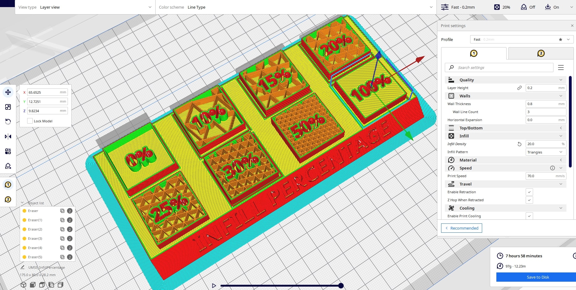 The finished file! (save to removable drive and start the print)
Repeat for infill pattern file:
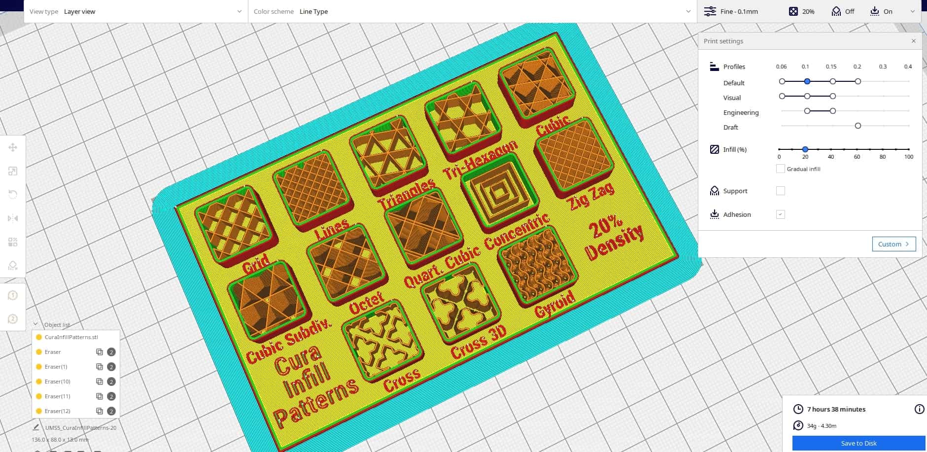 The finished infill pattern file (save to removable drive and start the print)
The results
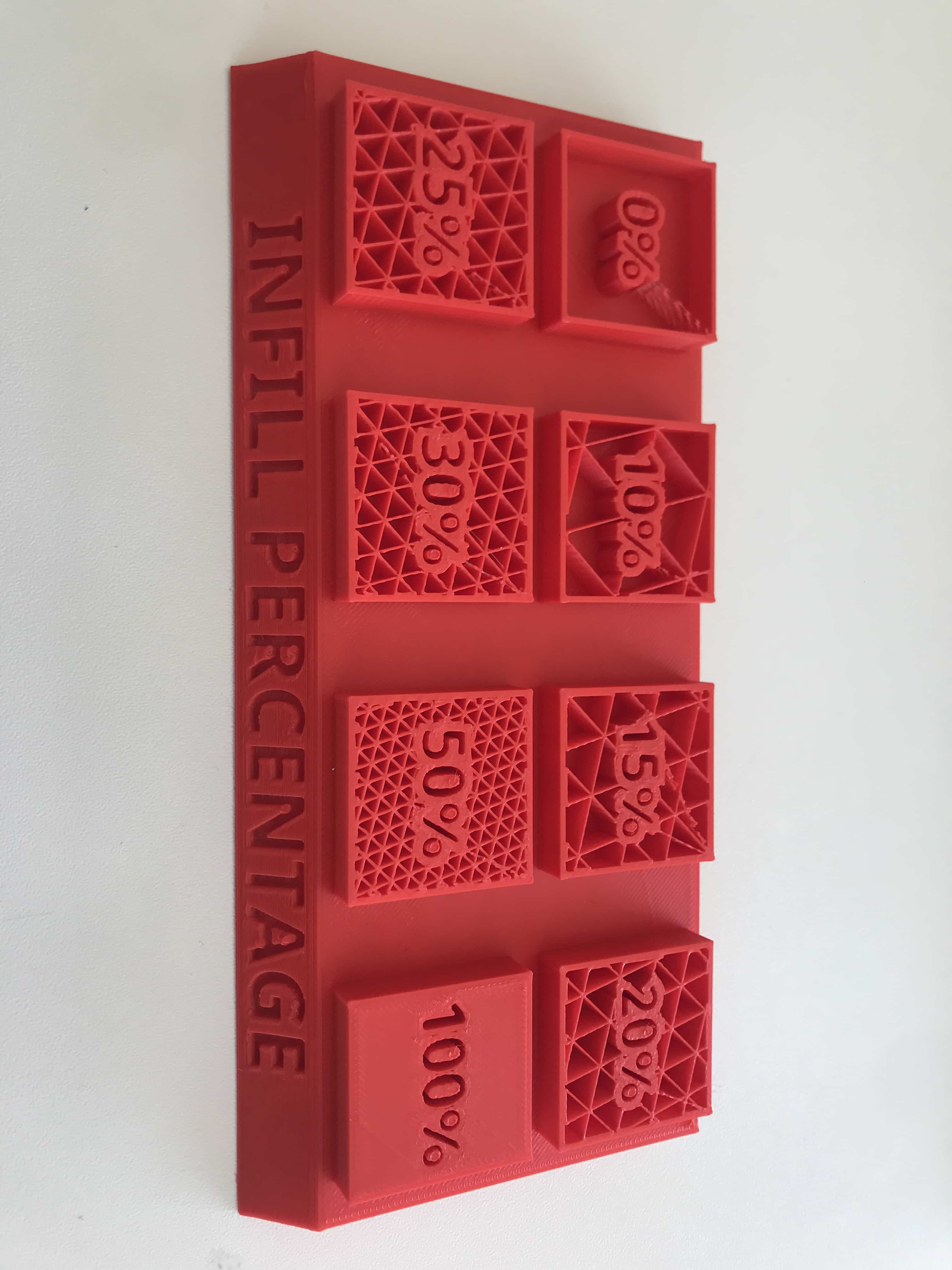 Here you can see the different printed infill percentages of the infill pattern "Triangles". Note that a bit of stringing occured with every percentage. All the >=20% infill percentages were very sturdy (the ones below as well, but a bit more bending was possible).
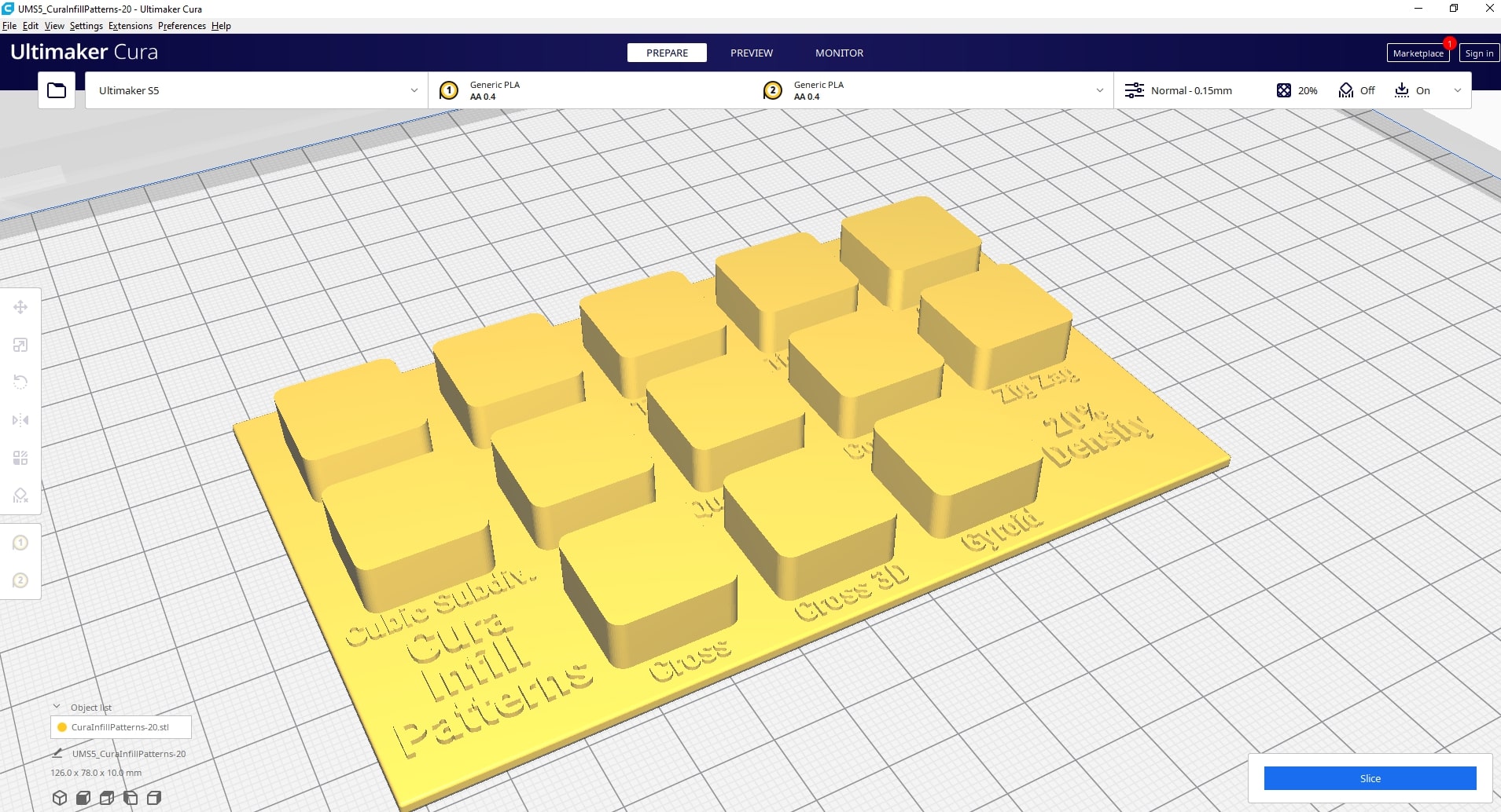
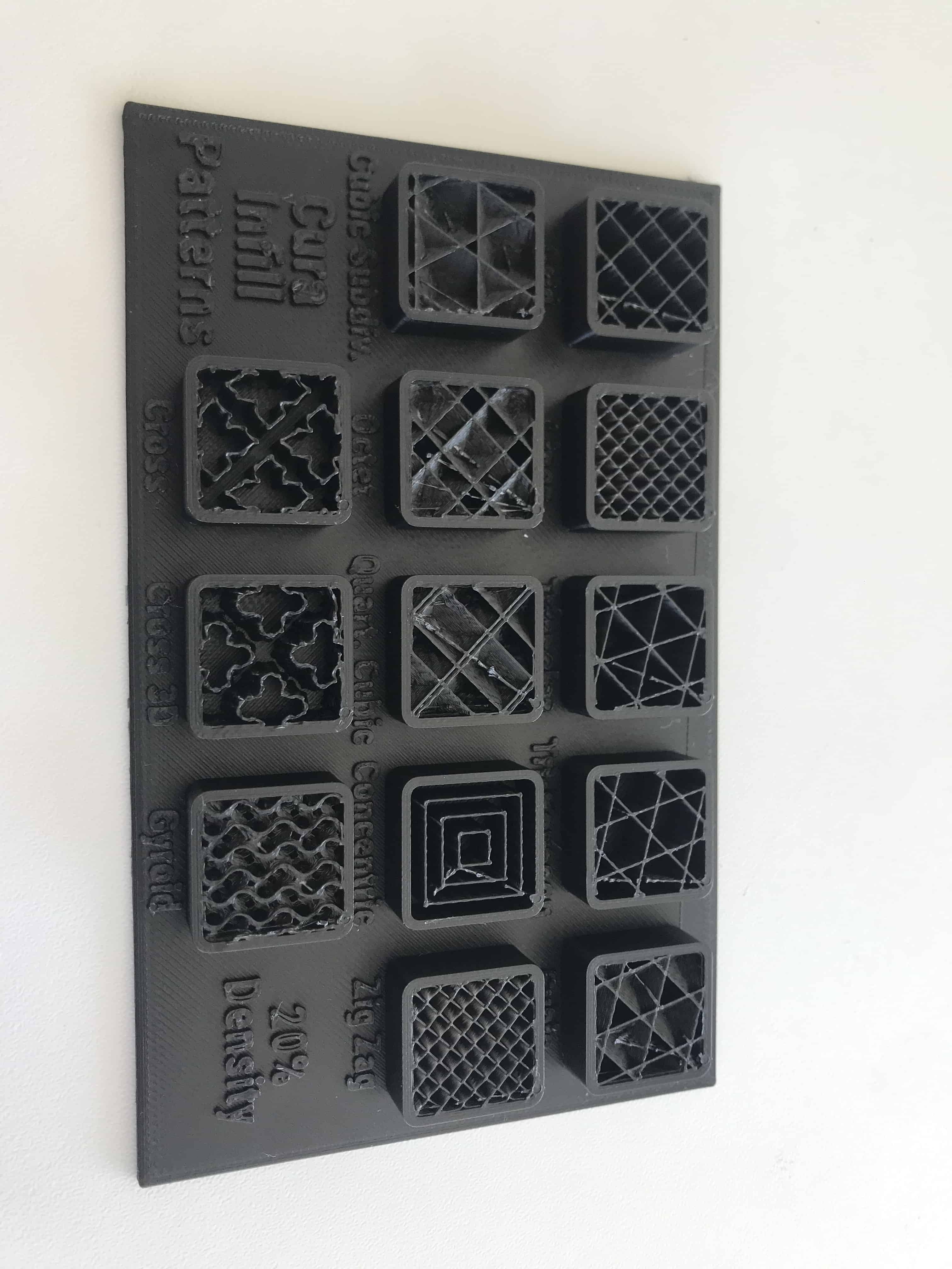 These are the different infill patterns at 20% density. Patterns like "Lines", "Zig Zag" and "Gyroid" seemed to be very sturdy, while "Concentric" was quite bendable.