Assignment 12 - Mechanical/Machine Design
Machine Building Week - FabLab Kamp-Lintfort
The idea for our machine is to recreate a simple two axis (If the time allows it even three axis) machine that can take gcode and draw on a piece of paper as a proof of concept. Since we are only two people on site at Kamp-Lintfort, the work was divided like follows:
- Electronics and if the time allows, a Z-Axis
- General strcuture and X/Y-axis
My part was the electronics part where I had the idea of creating my own CNC shield witht the microcontroller directly on board as to only have a single PCB that would control the machine. Sadly I had many things happen privately during this assignment, I could not really finish my task and so the machine is more or less not present at this time. I will try my best to catch up this week, though.
Electronics
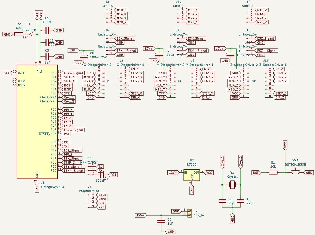
I started my project of the CNC shield by taking a look at the ones that were commercially available. On these Breakout Boards one can find four "slots" where the stepper motor driver blocks would fit in, as well as a handfull of pinouts, reaching from the enabling of the driver blocks to limit switches and even pins for controlling a coolant system. What all of these boards had in common however was the fact that they were seated ontop of an Arduino Uno, taking advantage of almost every pinout the Arduino has to offer. With this setup and a software called "GRBL" (can be found here) up to four stepper motors and six limit switches can be adressed and controlled through gcode when told so through a serial connection. Here the biggest problem I would have to face could have been easily preventable. I was under the assumption that I could just pcik every pin I want (as long as it supported what it needed to support for its functioning), so that I could freely design my own Board. As it turns out, this is sadly not the case. While you can change the pins you want to use, there are some rules that need to be followed. First and foremost the rule, that the pins for the steps of the driver blocks and their direction pins all need to be on one port respectively. Having two step pins on one, and the thrid pin on another port is not supported by GRBL. I have not seen this restriction at this time and so designed my Board with a lot more freedom for pin placerment in mind. I started the design process by adding the microcontroller that I was going to use for this project: The ATMega328p. I did not have a huge choice here, as GRBL is primarily setup for the Arduino Uno and so for the ATMega328p. After reading the most important bits and pieces from the Microcontrollers Datasheet and taking a look at the SatshaKit by Daniele Ingrassia, I felt ready to now come up with my own design. There were some things I had to have in mind, that were different to my Boards up until this point. For one, I needed to have a 12V input source as the motors were relying on this voltage. After taking a look at the parts we had on hand at the lab, I noticed that we had small screw terminals, so I used one of them in KiCAD as the port for the incoming Voltage. In order to not fry the microcontroller in the process, I also added a linear voltage regulator (L7805) that steps the voltage down to 5V from 12V-36V. With this regulator I could now create tow seperate voltage lines on the microcontroller. 5V for the microcontroller and 12V for the stepper drivers powering the stepper motors. I added the needed capacitors for the power delivery and moved onto the stepper driver blocks. My plan was to create a two by eight row of female pin headers for each driver block as I have seen them on the commercial boards and thought it was neat that you could just change out a driver block if it fails or for any other reasons. Since I could not find a ready to use footprint for the driver blocks, I measured the distance between the legs on one of the driver blocks in the lab and approximated the distance between the two eight pin rows, which came out to be around 12.7mm. Since we had no plan to use a second helping motor for any of the axis, I created three of these female pin headers with the stepper drivers we wanted to use in mind (SilentStepStick TMC2100). It was at this time, that I noticed that it would not be a trivial task to route all of this later on. Before thinking too much about this however, I added the last few parts, that I needed. I added a power indication LED, a 16Mhz crystal of which I also did not find a footprint and just created my own from one of the available ones, as well as a reset button. I also added six pairs of one by two pin headers for the limit switches (X+/- | Y+/- | Z+/-). On top of that I added a one by four pinheader to programm the microcontroller using the reset, the MISO/MOSI as well as the SCK pins from the MCU. Last but not least, I added a one by three pinheader with RX/TX and Reset, to later on use my own FTDI Cat to use serial communication. In the end, this was my final schematic:
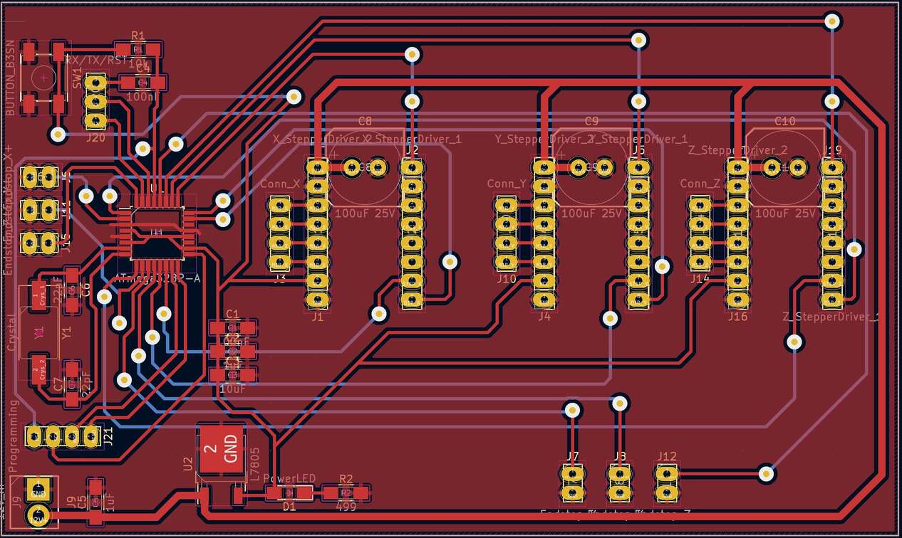
As it turned out, I was right earlier on, when I already thought, that the routing of all the tracks would be very hard. I tried my best to route everything the way I wanted, but in the end I was unsuccessfull. I first thought about using a multitude of zero Ohm resistors to bridge between all the tracks I needed, but this seemed like a stupid idea. It would take really long to solder all these resistors and on top of that the resulting board would look very crowded and just not as nice as it could be looking. My second thought directly fell onto using vias and creating a second side of the Board where everything that I could not route over the top layer, could be routed through the bottom layer of the copper. After asking my instructor about this, he said to me that this would be not so easy, but certainly doable. So I went ahead and created vias where they were needed. With this approach I was able to route evrything to my liking. After going over the board with Ahmed, it was pointed out to me that the vias were far too small and the trace for the 12V system would also need to be bigger as to reduce overheating. After I made changed to the board accordingly, this was my final layout:
- Arduino Uno Pin 10 to Reset
- Arduino Uno Pin 11 to MOSI
- Arduino Uno Pin 12 to MISO
- Arduino Uno Pin 13 to SCK
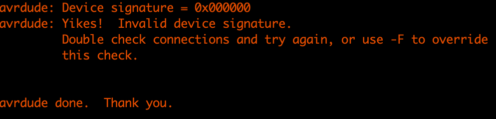
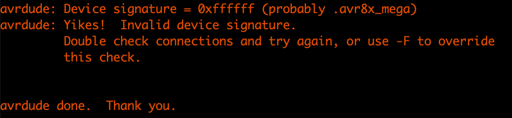
At first we got an error when trying to burn the bootloader. The error we got told by the arduino IDE was that the chip had a wrong signature:
In the lab we were able to almost immediatly get the Board to show the GRBL welcome message through serial. While I redid all the Vias with solder and checked every connection at home, we did this again and were able to read out over serial. What wasnt possible however was sending Gcode or any kind of GRBL commands like "$" or "$$". The whole day was then used for troubleshooting the board as a whole. The steps we undertook were the following:
- Reflowed all the vias again
- Reflowed the MCU connections
- Reinforced thin traces with cables
- Swapped out the Crystal
In the end we werent even able to get the Bootloader to the chip again. Everytime we tried we were greeted with this false signature error from above. It was at this time that Ahmed suggested to take a closer look at the reset circuit. And here was the big problem. I designed the reset circuitry completely wrong. Instead of pulling down the reset pin with each button press, the button shorted VCC to GND. Thuis mistake is so stupid that I am really ashamed this happened. This meant more or less, that the MCU was fried and that I had killed a 328p. The solution was rather simple. I just had to relocate the pull up resistor to sit between the button and VCC instead of between the button and RST. This was possible due to lucky pad distancing on the board. I could just switch them around and only had to trim one trace with the manual drill at the lab. After I have done this I desoldered the dead 328p and soldered on a new one. After we thoroughly checked, that the reset was now working and not shorting VCC to GND anymore, we tried burning the bootloader again. Again, no luck. We still got the error from above, actually multiple variations of this error:
- Device Signature: 0xffffff
- Device Signature: 0x000000
- Device Signature: 0xXXXXXX, where the row of X's were seemingly randomized
At the end I think I dont get around to redo the whole Board. Redo the mapping to conform to GRBLs standard, fix the Reset circuitry to completely, get the crystal closer to the Chip, not use six seperate pins for the limit switches, but share X+ and X- on one pin. Sadly this whole troubleshooting thing took place on the thursday before the lecture, so im still in the middle of redesigning the Board. I will update the page here with the redesigned Board and the working machine however.
In the meantime, to get to know GRBl, I used one of the industruial CNC shields we had at the lab. I did not notice it at all, but the first one I got had a tripped fuse and so was not giving power to the motors. After some time of troubleshooting with Ahmed we noticed the tripped Fuse and got another Shield. With this it was really easy to get the motors to move. I installed GRBL on the UNO, plugged in the Shield, plugged in the motor drivers and plugged in the motors next to the drivers. For controlling GRBL I was recommended to use Universal Gcode Sender. After connecting to the serial port within the application I was able to move the motors just fine: