To showcase the process of milling at our Lab in Kamp-Lintfort, we just used the traces and outline images from the line test from the lecture found here and here. After downloading the images, they could be used in Mods directly.
After opening up Mods, you just have to Rightclick > programs > open server program > machines > Roland > mill > MDX-20 > PCB png. This
opens up the server program for the Roland MDX-20 milling machine.
The Lab in Kamp-Lintfort has a Roland MDX-40 mill. This mill specifically is not (yet) part of the server programs list. This means that we had to change
a few values in order to get the toolpaths to work for our machine in the lab. At our local lecture our instructor Ahmed went over what we had to do in
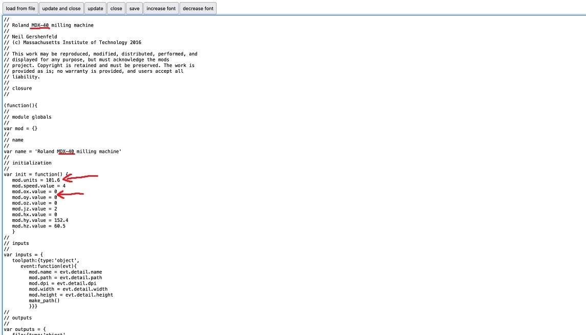
order to make Mods work with the MDX-40. By clicking onto edit right under the name of the MDX-20 node within Mods, you are able to change many parameters
that are not part of the node when you just look at the server program. The most important change to do, is to change the value of mod.units in
the initialization section from 40 to 101.6. Ahmed told us that he calculated this value for our machine. The other values we changed here were
mod.ox.value and mod.oy.value which we set to 0 instead of the standard 10. We the changed the name of the milling machine to
resemble the changes in the node overview of the server program. The edited file for the MDX-20 can be seen here:
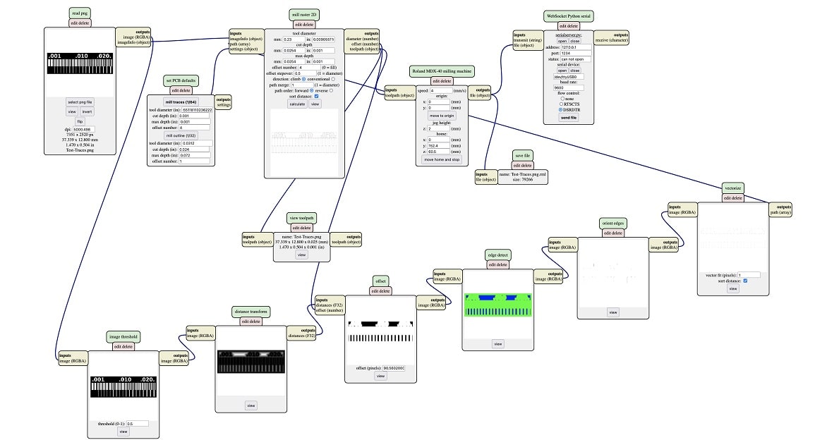
With the values changed in order to work with the milling machine in our lab, we could start loading in the pngs respectively. We started with the traces. Here we changed the following values (recommended to us by Ahmed) based on the different nodes:
mill traces (1/64)
Finally we inserted a file saving node by Rightclick > modules > open server module > file > save. The input of this node was then connected to the ouput
of the MDX-40 node. We were now set to calculate the tool path or the traces and did so by pressing the calculate button on the mill raster 2D node.
After Mods was done calculating the traces, we had a look at the result by clicking on the view button right next to the calculate button we pressed before. There everything looked good, so we continued to create the toolpath for the outline cut. Here we uploaded the png and replaced the traces png. Since the drillbit for the outline cut was bigger, we had to change a few settings to create the propper tool pathing. Here are the changes we made based on nodes:
mill outline (1/32)
With these changes we once again pressed calculate on the mill raster 2D node and viewed the resulting toolpath by pressing the view button next to it. Here
everything looked just as good as with the traces before.
This meant that for the line test cut everything was prepared file wise. This is when we went on to the milling
machine.
As already mentioned above, the mill at our lab is the Roland MDX-40:
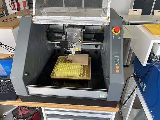
The mill is equipped with a vaccumable sacrificial layer to keep the piece you are cutting in place. Our instructor told us not to use this vacuum function as the waste produced by milling could simply be vaccumed into the machine and harm it. So instead of using the vaccum functionality, we used Tape to stick the copperplates onto the layer.
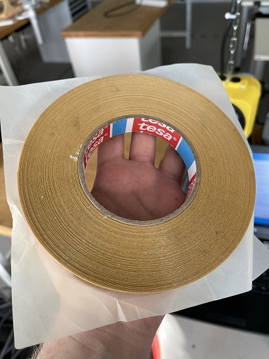
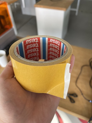
After we gathererd a piece of copperplate that would fit the cut almost perfectly, we used the tape and stuck the copperplate to the lower left corner of the vacuumable layer.
Since now the copperplate was stuck to the layer below, we could commence with changing the tool of the machine and homing it to the correct psoition in order to cut properly.
For the tool changing we used two wrenches and loosened the tool very slightly pressing a little bit against it with a finger to not let it fall and break. The new tool was
then inserted and fastened hand-tight. All in all the tool changing process was very simple to do and easy to understand. Next up was homing. For this we went onto the laptop
which was connected to the MDX-40. Here a program called Roland VPanel for MDX-40A was running.
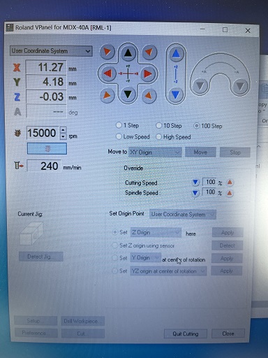
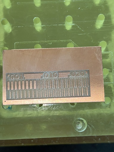
Here the user can set the rpm of the machine, its X/Y/Z-Origin points and even override the speed setting we set in Mods before. The user can also just jog the head of the machine around freely. For the X/Y-Origin point we just used the normal jog function with the High and Low Speed setting to get the tool as close to the lower left conner of our copperplate as possible, leaving just a very tiny edge. The Z-origin was the hardest setting to set correctly. Our instructor showed us first how to do it properly. You have to have the drill running to not destry the tool when plunging too deep. With the drill running the user has two options. Using the auto leveling puck that comes with the machine or doing the Z homing by hand. For the smaller tool (that cuts the traces), we homed manually. We went with the step increments that you can select in the software. We used 100 steps to get relatively close to the copperplate and after that changed the steps value to 10 to get evern closer before doing fine adjustments with the 1-Step setting. All the while listening closely to the machine, as AHmed told us, that you can hear a difference when the drillbit is piercing the copperplate. I tried listening to this difference in sound but found it quite hard to make out. The other option to check if the Z-position is good, is to set the Z-Origin to the current value and after that moving the head up by a fixed amount of millimeters and using the machines View function to move the head out of the way and move the plate closer to the user. When you can just barely make out that the tool has cut a little bit away, the Z-Origin was good. In our case this process went on for approxiamtely 5 to 10 minutes until we found the Z-Origin point we wanted to use. Even before setting the Z-origin our instructor Ahmed told us, that a speed of around 15000 rpm would be suitable for cutting the copperplate, so we chose this rpm as our cutting rpm. This was the moment were we could begin cutting. I uploaded the tooplath file for the traces and the machine began cutting. Ahmed took a look at the cutting process and said that it went very smoothly. After the traces were cut, we used the View function to clean of the waste and take a look at the cut. The cut went very good and looked like this:
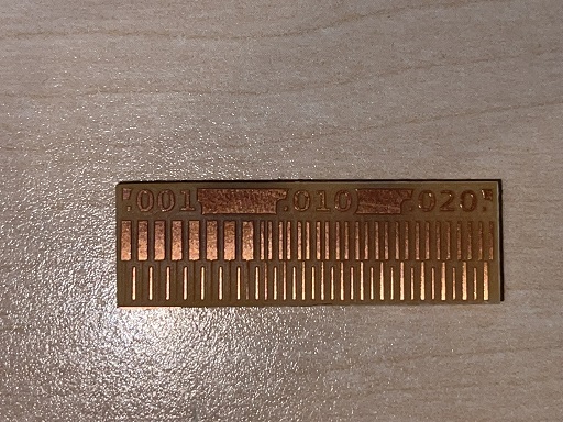
So after changing the tool to the 1mm bit and returning the head to its home position we laoded the toolpath of the outline into the program (while deleting the old toolpath file from the contextmenu) and started to cut again. After the machine was finsihed, we used a flat head scredriver to carfully push on the copperplate from the sides to loosen the tape, which worked very good. After removing the tape and cleaning the edges a little bit, this was the endresult of our cut on the MDX-40: