 Home
Home
Interface & Application ProgrammingRecaps and Task Outlines May 4th, 2022, the course continued talking about:
The objective of weekly assignment are:
Learning Outcomes After this course, I am able to
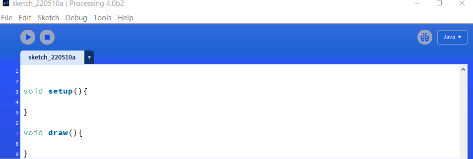
Able to make interface with internal interaction (mouse/keyboard) with UI Group AssignmentGroup assignment can be found HERE which about making simple interfacing with internal device like mouse or keyboard. IntroductionIn this weekly task, I start learning making apps (desktop and mobile phone) that can support my final project. As in my final project, I will make robot that can send informations filled with data measurements via wireless communication. Processing.orgWhat is this?According to Processing.org website, Processing is a flexible software sketchbook and a language for learning how to code within the context of the visual arts. Basically, it is based on Java and used for prototyping equipped with ability to visualize the process or events. Interesting right? The software we use for programming is free. It looks like the Arduino IDE that many people has familiar with. The difference between IDE with Processing is IDE has two functions automatically provided when opening it which are SETUP and LOOP, meanwhile, Processing has SETUP and DRAW as can be seen in figure below. The file extension for processing is PDE. In this task, I use processing version 4.0b2.
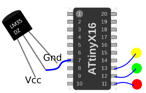
The board that I am using is ATTiny3216 breakout board that I made days ago. It already has socket pins that can be connected directly to any other external pheriperal. I use LM35 linear temperature sensor that gives analog value to microcontroller and three leds (Green, Yellow, and Red) as temperature level indicator. The reason I use LM35 in this project is because it has analog out so I can put formula to convert the read out from sensor to voltage then real temperature. LM35 as default will output temperature in celcius, ofcourse by dividing it with 10 mV first. The pin connection between the ATTiny3216, LM35, and LEDs is
The codesPROCESSING Declare serial libary to have wired communication between processing and microcontroller.
Create objects, here I want to use an image as background, use specific font-style.
In SETUP, add serial port object to initialize serial communication.
in DRAW, read serial value anytime it is available.
ARDUINO IDE Variables declaration
In SETUP, start serial
In LOOP, transmitting data will be
The user interface on processing is used as indicator of 2 things, the temperature value captured by LM35 and the LED indicator when it reaches some value. What I show in this demo is real temperature value measured by the sensor in my town, Yogyakarta. It is like the sun ray burnt the skin. You would see people wearing jacket in my town, funny, but true. The logic for later statement is coded as below:
Snippet above tells that when temperature is higher or equals to 35 celcius, RED circle appears on GUI processing. Then, red led is ON on the board as well.
Snippet above tells that when temperature is higher or equals to 30 but less than 35 celcius, YELLOW circle appears on GUI processing. Then, yellow led is ON on the board as well.
Snippet above tells that when temperature is less than 30 celcius, GREEN circle appears on GUI processing. Then, green led is ON on the board as well.
The way the conditional logic is written above is the optimized version. One can rewrite the code using symbol "<" and ">" to make easy reading, but that will make the codes longer.
Complete codes are attached beneath the video. Below is the demo video.
All files involved can be found on below link, I put enough explanation in them (I belive): Value in Text Object Dynamic changes in the text object's value is impossible to do as it will overlay older value hence the latest value will look messy. Mobile Phone ApplicationHere, I use two different communication which are Serial Bluetooth and WiFi (Cloud). I develop 2 different mobile application that can be used to read sensors and control the motor from simple car that I build using 3D printer. I use KODULAR to build the apps. KodularIn their website, they introduce kodular as follows:
"Kodular allows you to create Android apps easily with a blocks-type editor. No coding skills required. With the Material Design UI, your apps will stand out."
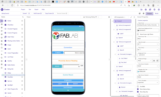
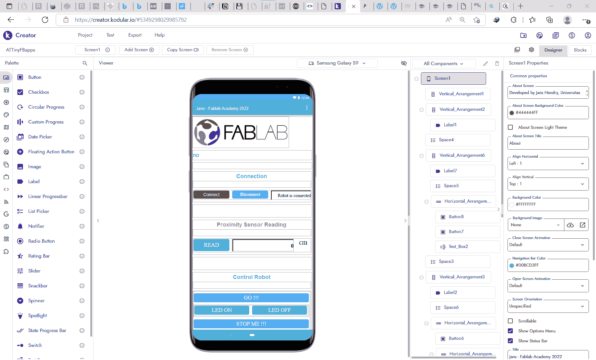
Simply put, I consider this to old platform that I used to use which is App Inventor. Below images shown 2 apps that I built to accomodate two different wireless communications. The left image is used for serial bluetooth, the right image is for cloud communication. Cloud database that I used is Firebase from google.
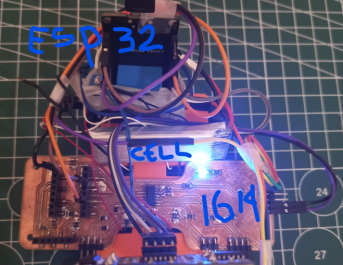
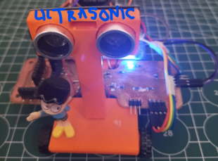
HardwareIn this task, I use ATTiny1614 board that I used for machine bulding task connect to ESP32 board as the helper for wireless communication. The sensor that I use is one ultrasonic sensor to estimate distance between car and obstacles. Added to that, for switching I use one magnetic relay connected to 4 small dc motors. This dc motors used to use for quadcopter, hence the RPM is so big.
Serial Bluetooth ApplicationBluetooth serial is accomodated in Kodular. Simply using Bluetooth Client. Following steps are how to connect with bluetooth and sending/receiving data.
The CodesESP32 To connect to bluetooth serial, use directive and create an object
In SETUP, to start serial bluetooth, use below code, with "ESP32 - Jans" is the name you put as identity of your ESP
In LOOP, if bluetooth is available (serial transmitting data) then read the data
If you want to send data via serial bluetooth, simply Use
There is no special instruction in ATTiny1614 for this case. I designed it to be that way so the main tasks will be handled by the ESP32. Complete codes are attached beneath this video. The demo video is shown below, left video shows the LED and sensor check, while the right video shows controlling demo.
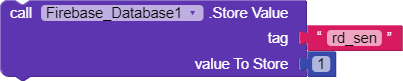
All files involved can be found on below link, I put enough explanation in them (I belive): [KODULAR] [ATTINY1614] [ESP32] WiFi ApplicationAs I mentioned before that I use cloud storage/database for this type of connection. It means that I can ask my robot and my app to write and read data to cloud database. I use google firebase to do this. Kodular has made this simple to access this database. We can directly access the database by using Firebase_Database and fill the Firebase Token and Firebase URL. You can leave the Project Bucket empty if you do not want to make parent key for all the incoming or outgoing data. Following steps are simplified version of how to connect kodular to firebase realtime database.
The CodesESP32 To connect to firebase database and wifi, use directive and create an object
Insert your credentials
In SETUP, do not forget to initialize
In LOOP, if you want to write value (float/int or string), use SET
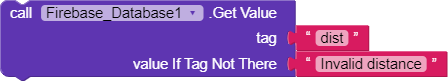
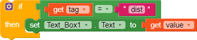
If you want to read from database, you can specifically write their data type. But to be safe, you can just use GET
There is no special instruction in ATTiny1614 for this case. I designed it to be that way so the main tasks will be handled by the ESP32. Complete codes are attached beneath this video. The demo video is shown below, left video shows the LED and sensor check, while the right video shows controlling demo.
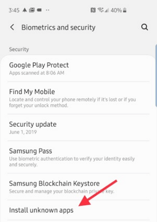
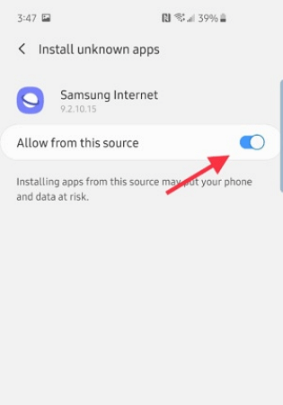
All files involved can be found on below link, I put enough explanation in them (I belive): [KODULAR] [ATTINY1614] [ESP32] Apps Installation on AndroidTo install your app in mobile apps if you use android is pretty easy by following this link. I rewrite them here:
I also want to check web serial to read sensors and control the small car robot. But I am not sure I have enough time for now. Hence, I will do that later when I have leisure time. |