 Home
Home
Communication and NetworkingRecaps and Task Outlines April 27th, 2022, the course continued talking about:
The objective of weekly assignment are:
Learning Outcomes After this course, I am able to
Test data transmit or receive on wired communication/network Group AssignmentGroup assignment can be found HERE which about testing as many as communication and networking device as possible. Background StoryWhile imagining the solution to this weekly task, I was thinking about how to learn as many as communication and networking facilities that a microcontroller can have. Then I decide to make two projects which are
In this project, I use two self-made microcontroller that I used for machine building task. One microcontroller used ATTiny3216, another is ATTiny1614. As I only have one ESP32 Board and one ESP8266 Board, hence I am gonna make two different program for both which I belive will not much different. The IoT platform that I am gonna use is firebase, thingspeak, and blynk. All of them will be connected to my personal-fabacademy-website. The project would be as shown below
In this project I would like to control LED connected to ATTiny3216 using ESP32 Bluetooth module. The system is simple and will only involve digital pin on both microcontrollers. The block diagram is shown below
By having both projects completed, I believe I would have chances to learn about wired communication like UART, I2C, SPI and wireless communication like WIFI and Bluetooth. Wired CommunicationWhat are they?Just because their name is "wired communication", it does not mean that they are literally wired. They are named so because they need physics media for data transmition which can be copper, cable, any media that can flow electrons, physically. There are atleast three types of wired communication that a microcontroller provides which are I2C (I squared C), UART (RS232), and SPI.
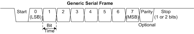
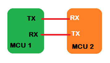
UART Communication stands for Universal asynchronous receiver-transmitter. It is a dedicated hardware device that performs asynchronous serial communication. It provides features for the configuration of data format and transmission speeds at different baud rates. A driver circuit handles electric signaling levels between two circuits. A Universal asynchronous receiver-transmitter (UART) Communication is usually an individual component or part of an integrated circuit. This is one of simplest communication that does not need handshaking and clock similarity as long as we put same baudrate to it, commonly is 9600. The problem is, if we send long message to it, some of them will be clipped. Generally, the bit by bit transmission can be described by below image. The communication between two pheripheral can be made by connecting opposite pins between TX and RX on each device, which means TX1 to RX2 and RX1 to TX2. See below image for clear description.
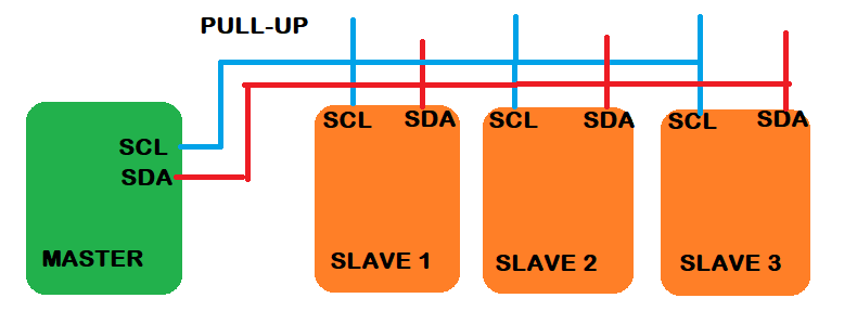
What most interesting is this communication is frequently used as bridge between USB and Microcontroller for program burning like UPDI, FTDI etc. I used this communication for various microcontroller like AVR, STM32. The aformentioned communication type is peer to peer communication or one to one communicaton. The I2C is different, together with SPI, can create one to many communication. But SPI is less efficient than I2C as it need 4 wires to setup communication. I2C only need 2 wires which are SCL(SCK) and SDA. SCL stands for Serial Clock Line and SDA stands for Serial Data Line. This communication can establish one to many communication as shown by figure below.
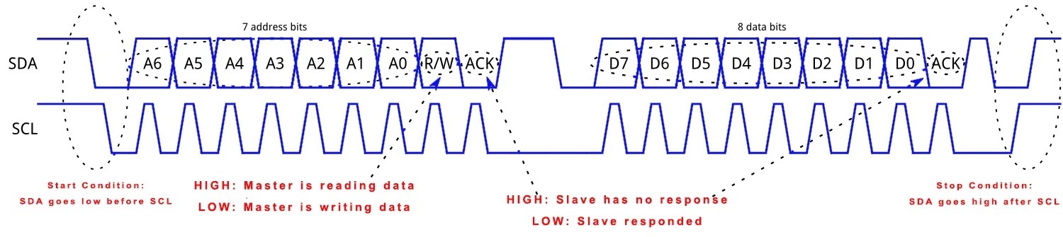
Meanwhile, the communication format is complex than other two as it needs to introduce address and master-slave acknowledgment process as it only use 1 wire for communication. Remember that UART have two wires (TX/RX) for direct communication. Below figure shows how the process is. This communication is used by Liquid Crystal (LCD), OLED, and some sensors. We should call Wire.h directive when using it.
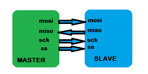
source: https://www.teachmemicro.com/i2c-primer/ The SPI is the fastest among others. But it requires 4 pins (MISO, MOSI, SCK, SS) to establish a communication. It also does not have ability to have more than 1 master. SPI communication, which is also known as Serial Peripheral Interface, is a digital communication protocol that is used to transfer data serially (one bit at a time) between two or more digital devices like microcontrollers, microprocessors, or other devices. This communication type is used by many displays like TFT, Capacitive TFT (Adafruit), and some sensors. The communication can be considered simple than I2C as it merely comprises of simple shift register. We should call SPI.h directive when using it.
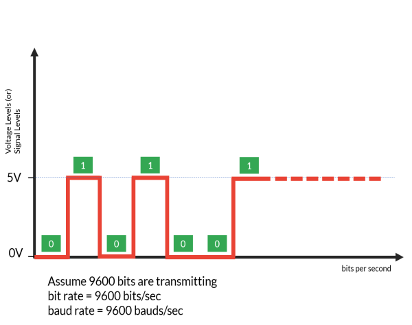
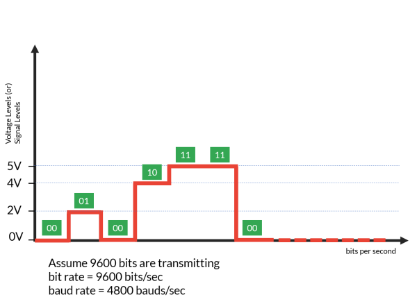
What is baudrate?We always use this one guy everytime we establish communication between computer and microcontroller. Baudrate can be defined as the number of signal or voltage level changes per second. If we transmit length of bits 115200 and we are dealing with TTL where '0' represents 0 V and '1' represents 3.3 V or 5 V, then baudrate is 115200. It means there is 115200 signal changing happens in one second. But when the level of voltage is made to 4, for instance 0, 2, 3, 5 V where it will be represented by 2 bits (2^2 = 4 level), then baudrate is 115200/2 = 57600. See below figure as illustration.
source: https://bytesofgigabytes.com/ Wireless CommunicationAtleast there 2 wireless communication that we can have in microcontroller project:
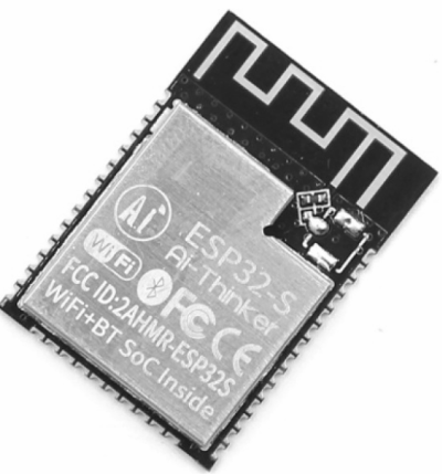
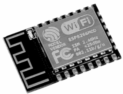
is a means of peer-to-peer (P2P) communication (Direct Communication only between 2 nodes). Bluetooth technology operates in the unlicensed industrial, scientific and medical (ISM) band at 2.4 to 2.485 GHZ, using a spread spectrum hopping, full-duplex signal at a nominal rate of 1600 hops/sec. the 2.4 GHZ ISM band is available and unlicensed in most countries. Bluetooth operating range depends on the device Class 3 radios have a range of up to 1 meter or 3 feet Class 2 radios are most commonly found in mobile devices have a range of 10 meters or 30 feet Class 1 radios are used primarily in industrial use cases have a range of 100 meters or 300 feet. Bluetooth supports 1Mbps data rate for version 1.2 and 3Mbps data rate for Version 2.0 combined with Error Data Rate. Wi-Fi, a brand name given by the Wi-Fi Alliance (formerly Wireless Ethernet Compatibility Alliance), is a generic term that refers to the communication standard for the wireless network which works as a Local Area Network to operate without using the cable and any types of wiring. It is known as WLAN. The communication standard is IEEE 802.11. Wi-Fi works using Physical Data Link Layer. Nowadays in all mobile computing devices such as laptops, mobile phones, also digital cameras, smart TVs has the support of Wi-Fi. The Wi-Fi connection is established from the access point or base station to the client connection or any client-to-client connection within a specific range, the range depends on the router which provides the radio frequency through Wi-Fi. These frequencies operate on 2 types of bandwidth at present, 2.4 GHz and 5 GHz. ESP32 as well as ESP8266 can recognize only 2.4 GHz band, so make sure that the router does not use 5 GHz. ESP32The ESP32 produced by espressif to handle wireless communication like bluetooth and wifi. It acts like a node that can be a master (act like a hotspot) where other device can connect to, or a slave the one that connected. The ESP8266 or popular with NodeMCU has been used by many people since it was launched. Then the glory is taken by its sister, ESP32, with many benefits compared to its predecessor. There are a lot of libraries have been developed for both microcontroller in Arduino IDE to ease the prototyping. Then, many developer has built various development board (breakout) that embed both ESP so users don't have to make their own downloader. Nowadays, making downloader for both is easy by using FTDI that utilize UART communications. Below figures are examples of both micro without the breakout.
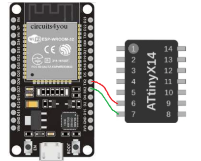
Demo - Wired CommunicationUARTIn this demo, I board with ATTiny1614 where the RX and TX connected to RX2 and TX2 of ESP32. Generally, ATTiny has only 1 UART while ESP32 has 3 UART. So, I connect them according to below figure.
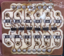
The only problem left now is that the fact ESP32 can be operated only with VCC = 3.3 V, while I was using VCC = 5 V (from USB port) for ATTiny1614. So, I made my own level shifter (logic converter) from 5 V to 3.3 V using N-Channel Mosfet BSS138 that is shown by figure below. In this part, I also did experiment to make double-layer PCB using 0.9 mm rivet (this is the smallest diameter available in our country). By using this level shifter, I can transmit data with different voltage level. You do not need this when you operate ATTiny with VCC = 3.3 V, remember that.
Below is snippet of code in ESP32 to initialize UART2. The RX2 pin is GPIO16 and TX2 pin is GPIO17 are initialized on the top.
Then, fire up serial2 with associated pins.
Remember that the data transmitted by UART singly. So, in the loop, have a variable to store them completely. Also, have a check whether data sent from ATTiny has reach the message's tail. This tail can be anything, in the Attiny I use '\0' which is NULL symbol sent to ESP32. This symbol always present in a string. Oh, one thing, remember that data transmitted and received is always in character/string data type.
The sensor that I used to gather data is Reed Switch to detect presence of magnetic. I need this sensor for my robot as my robot will navigate over magnetic tape.
The snippet code in ATTiny1614 is below. Convert read out of sensor to String data type.
Then use LOOP (FOR/WHILE) to send data. Loop is not needed when data length of digit or string is one. But for safe operation, consider to always use LOOP. Right after LOOP, send '\0' to close the transmission.
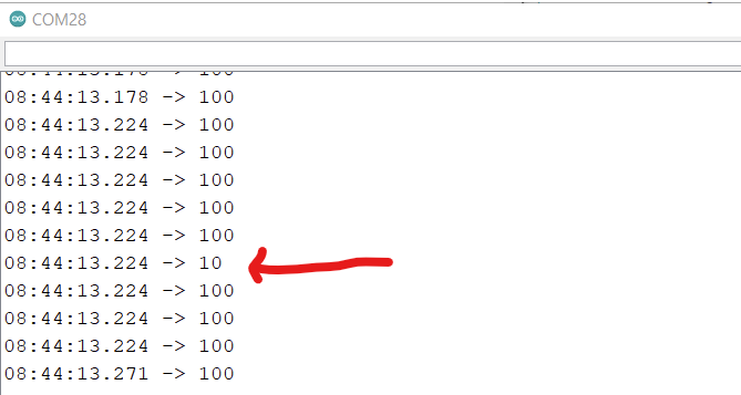
Do not forget to use delay, perhaps atleast 100 ms, after every transmission. If not, the received data can be clipped anytime (not always, but possibly) as shown by figure below.
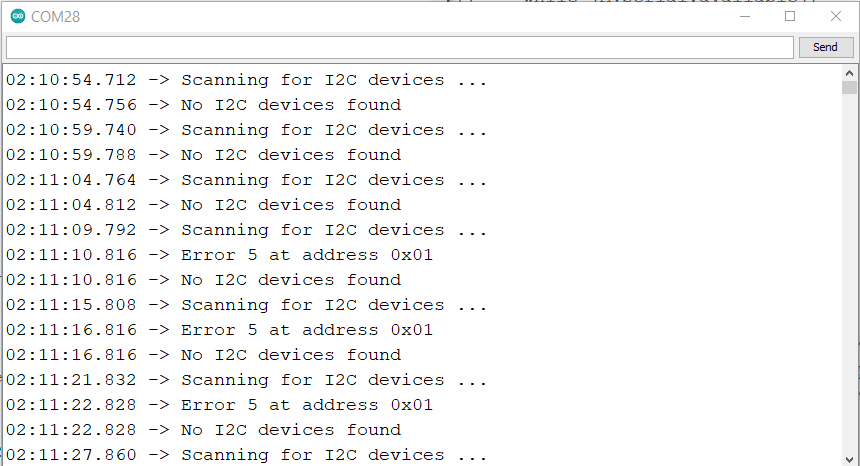
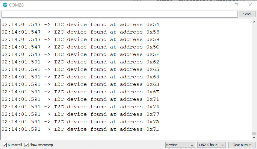
Here is the demo of transmitting reed sensor data from attiny1614 to esp32. All files involved in this demo can be found on below link, I put enough explanation in them (I belive): [Level Shifter] [ESP32] [ATTiny1614] I2CSimilar to UART, pin connection between 2 devices is easy to implement. But in UART, we should do cross connection between TX/RX of first device to RX/TX of second device. While in I2C, we connect them as it is without cross connection. In this experiment, I use my own level shifter to bridge the ESP32 and ATTiny1614. Based on experiment, it is what it needs. If I connected the I2C directly between 2 devices, the error keep arising in serial monitor when I try to scan pinged address between both devices. The most critical problem in I2C connection is to set correct address for both devices so communication can be established. The problem is have tested various address for both of them but still no data received by the slave. This can be done easily using board like Arduino UNO as we can just use address "9". But list of address for ESP32 and ATTiny1614 for instance 0x54, 0x55, 0x09, and so on did not work. So I decide not to continue this experiment and would work with UART communication for my final project. I need to get wired communication suits my need because I am going to send data from sensors that read by ATTiny3216 to cloud service using ESP32. It means that ATTiny will send data to ESP32 over wired communication, that is UART. Here is the image that shows the experiment that I did. Left image shows when I did not use level shifter where address scanning keep showing error. Right image shows that when level shifter is used, the error dissapear but the address did not show single address like when we connect specific device like LCD liquid crystal where the address can be 0x27 or 0x3c.
Demo - Wireless CommunicationIn this demo, I provide 2 type of wireless communications which are WiFi and Bluetooth. I digged more about WiFi where I connected them with cloud service. PROJECT 1Some preparation is made which are connecting LCD as display and sensor as input. I choose peripherals that have communication on it. So I choose LCD Crystal Liquid 20x4 that uses I2C. While the sensor that I choose is analog/digital sensor that can be arbitrarily connected to ATTiny3216. LCD Display (I2C)The LCD display that I used here is 4x20 LCD has address on 0x27. This LCD is used to display information about what is going on. I use default pin for I2C ITTiny3216, but we also can use alternative pins which are pin number 17 and 18 (which orignally for MOSI and MISO). I tested those pins and it works as well for the display. No special requirement for connection, we just connect each pins according to pin assignment as shown by figure below.
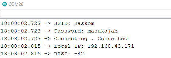
WiFi ConnectionWiFi connection is started by giving SSID and Password inside the IDE program. But, we can actually do WiFi Scanning prior to connection. I did that before making this project and decided to drop it as I found it difficult to enter password without keyboard attach to microcontroller. But, it will be fun if your WIFI project has such feature. When the connection is succeed, you would get something like this:
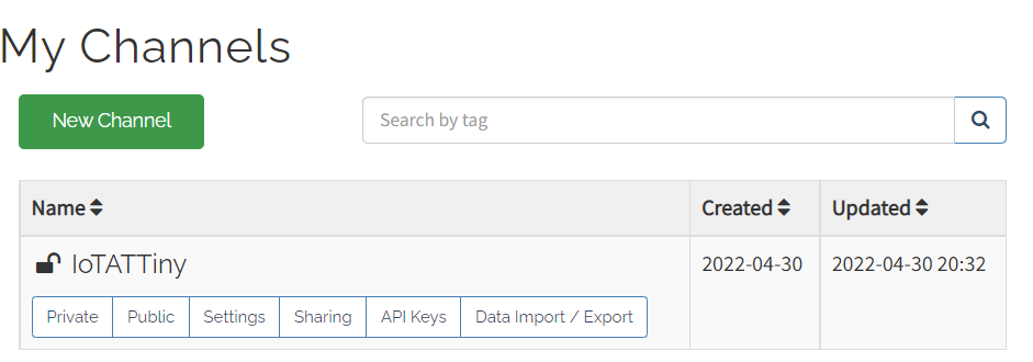
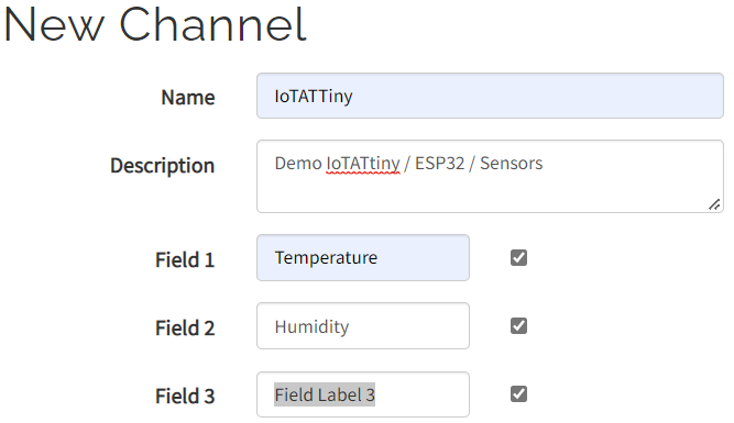
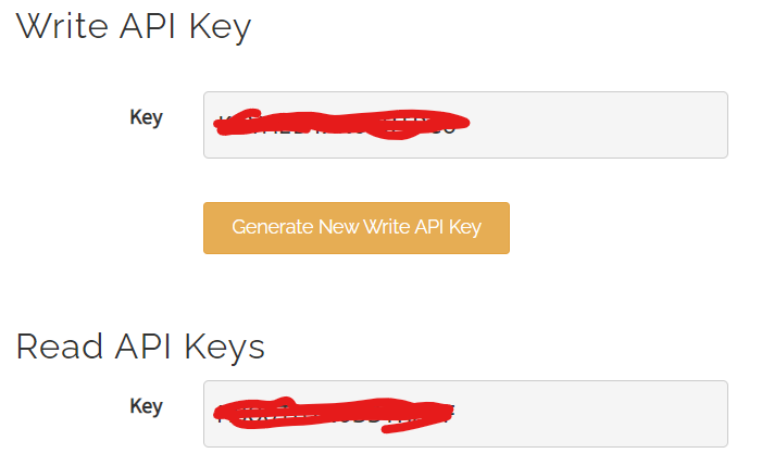
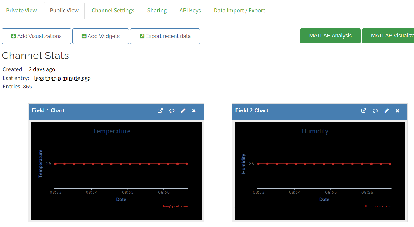
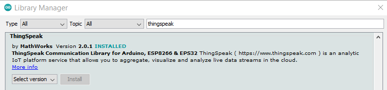
ThingSpeakThingSpeak is an cloud service that we can use to read data from node(s), store and visualize them in real-time mode. Real-time defined with your internet connection speed. The reason I use this tool is because we can visualize our data without writing code inteded for visualisation. But this service only serve for maximum 8 fields, which means we can only send 8 different variables to the service to store. This service also give simple embedding process to our website by only copying link they provided for each widgets like temperature and humidity curve you see below. Added to that, this service also provides some widgets that we can embed to our website easily, like LED indicator (big circle) that I attached in this website. Here is the webacademy linked with ThingSpeak in realtime mode
Whenever the temperature reaches value more than or equal 30, LED will ON (GREEN) as shown below. On the contrary, it will be gray. It also applies to the ATTiny1614 as the cloud-recepient.
Here are the steps for ThinkSpeak, which is relatively easy:
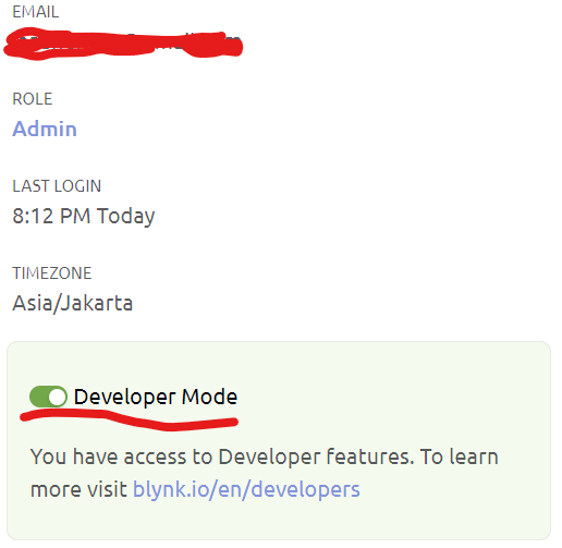
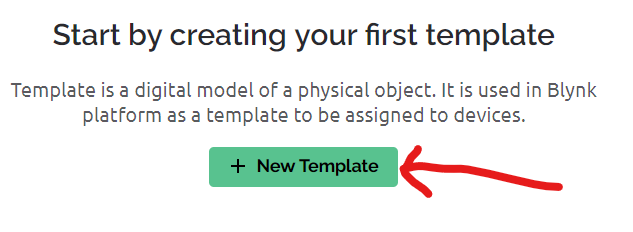
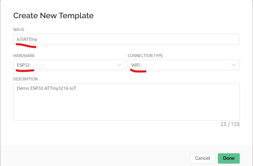
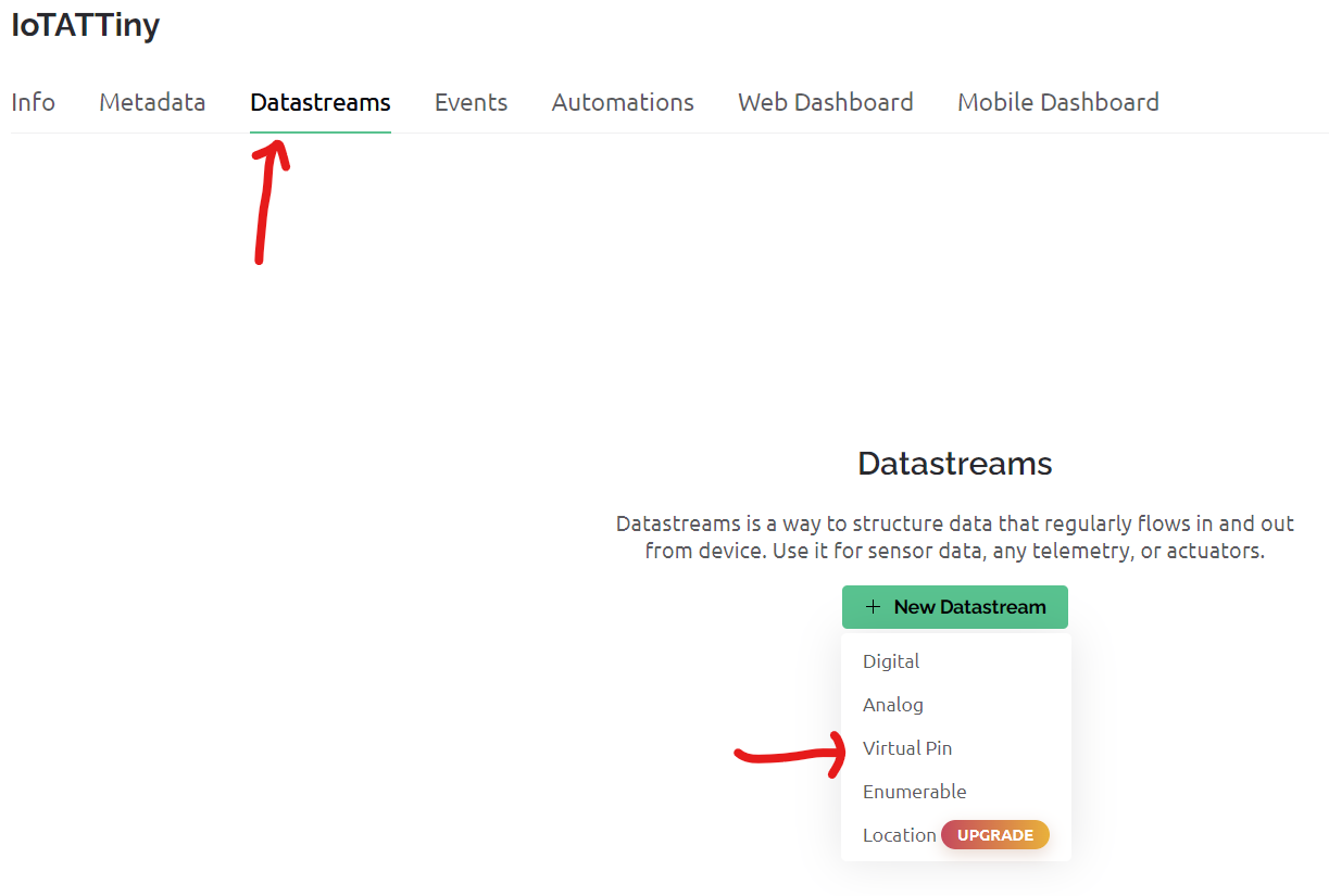
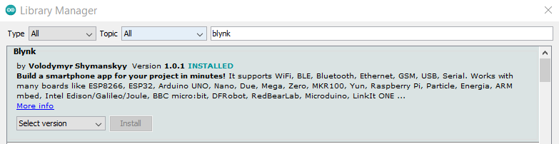
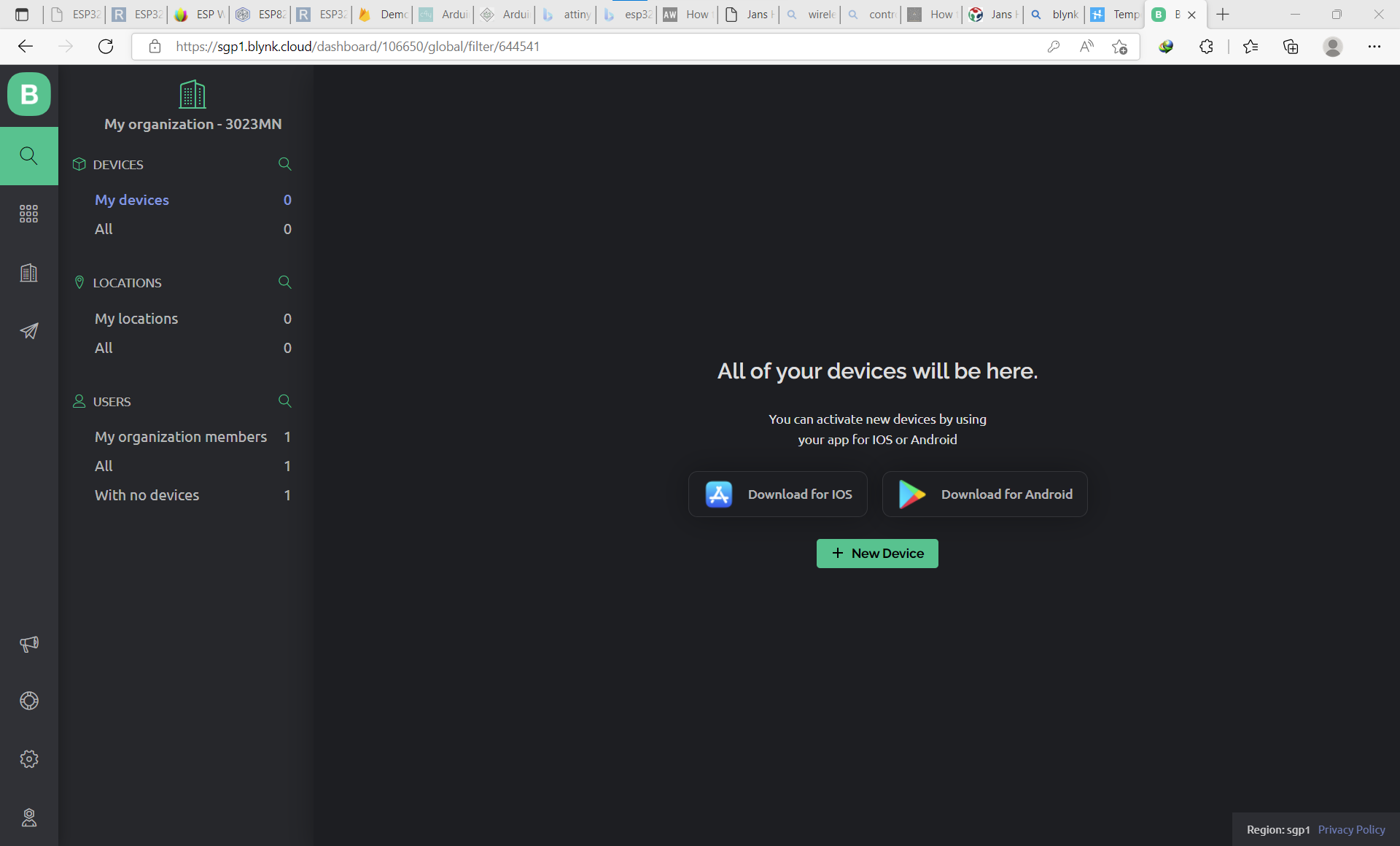
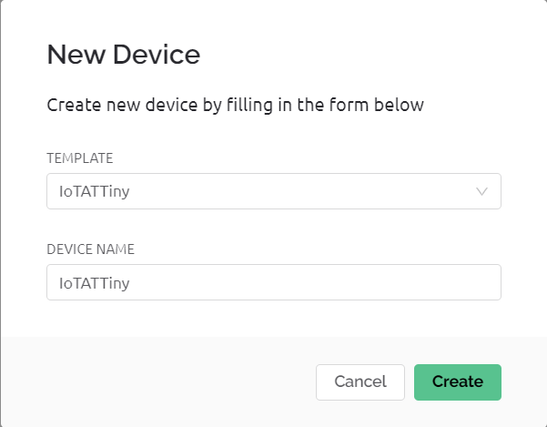
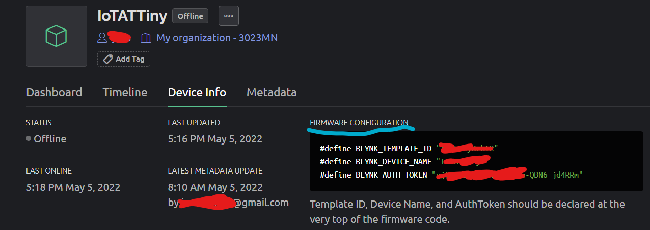
Based on my experiment in wired communication, I decided for this project only using I2C and WIFI for wired and wireless learning. Also, I used same device ATTiny3216 and ESP32 as transmitter and receiver to and from Cloud as I found it difficult to plug and play many board using only one laptop. I was thinking to use different ESP32 and ATTiny board as reciever from cloud data but it will be complicated as I have to provide more USB port to supply VCC which I don't have. Here is the demo. The LCD became dimmed because servo takes more current (servo is active peripheral) for it to run and LCD is passive peripheral hence it will lose the battle LOL. The benefit of using ThingSpeak is it visualizes data from sensors. Hence, we do not need to make codes for this. The lack is it only provides 8 fields, which perhaps it is enough for simple project. Also the update in ThingSpeak takes about 2 seconds, so you would find that measured value in micro is different to what displayed in ThingSpeak. All files involved in first project (ThingSpeak) can be found on below link, I put enough explanation in them (I belive): [WiFi Test] [ESP32] [ATTiny3216] BlynkLuckily, Blynk still provides us free account that can help us to connect our device with cloud, unlike the MQTT as I would explain after this. Here below the simple way to make your hardware connected to cloud, in this case is blynk. Differ to ThingSpeak and Firebase, All what Blynk provides us are widgets that we can easily drag and drop to website app. Then we do setting to the widget to fetch appropriate values from our hardware. There is no limitation in field, so it won the battle to ThingSpeak. In this task, I use ATTiny1614 board that I developed to control servo, pump, and stepper motor for our maching building task. Steps to make IoT project usign Blynk:
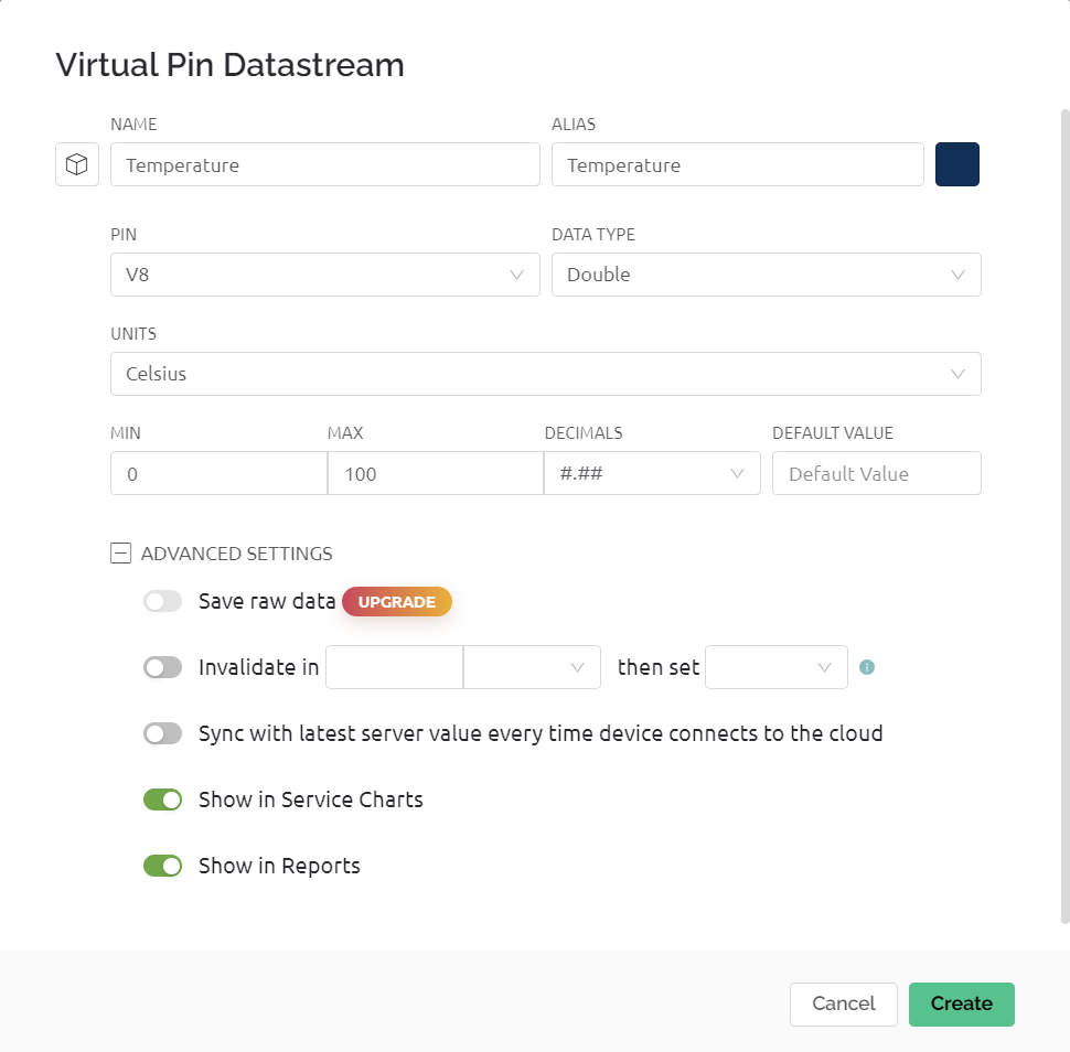
Example of adding a datastream
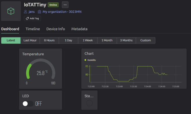
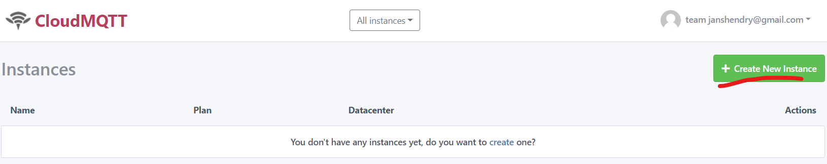
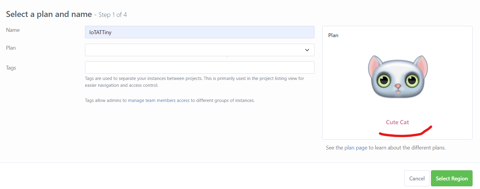
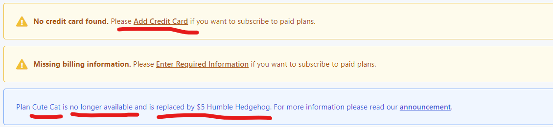
Here is the video that shows how my devices connected to Blynk cloud-service. What I dislike from Blynk is it does not give us iframe embedding like ThingSpeak does to personal website. We should open their website or app to get what we already made. We can ofcourse can use Node.js or other features that they have provided. But, I just want to embed all what I already made in their web app to my personal webacademy website. All files involved in first project (ThingSpeak) can be found on below link, I put enough explanation in them (I belive): MQTTMQTT stands for Message Queuing Telemetry Transport, it’s a system where we can publish and subscribe messages as a client. By using MQTT you can send commands to control outputs, read and publish data from sensors and much more. There are two main terms in MQTT i.e. Client and Broker. MQTT Client: An MQTT client runs a MQTT library and connects to an MQTT broker over a network. Both publisher and subscriber are MQTT clients. The publisher and subscriber refer that whether the client is publishing messages or subscribing to messages. MQTT Broker: The broker receives all messages, filter the messages, determine who is subscribed to each message, and send the message to these subscribed clients. With MQTT protocol, we can communicate to mobile phone apps to write or read data in IoT platform. At early stage, the developer provided free access that we call as Cut Cat Plan where we can add instances freely. But now, this feature is removed and user is charged at minimum 5$. Here are the steps to make an account in MQTT website:
You will find information that Cute Cat Plan is no longer available. So you should deposit minimum 5$ to start. I stopped, as I don't have money to purchase it.
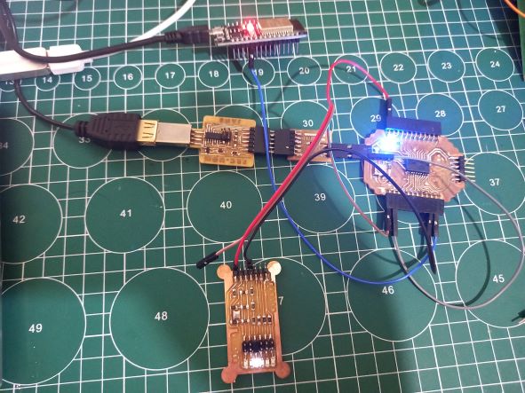
PROJECT 2In this project, I made a connection between ATTiny3216 and ESP32 using digital pin. The digital pin works as signal from esp32 to attiny to turning on or off LED. I made LED module that I used for previous weekly task which was measuring power consumption.
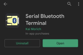
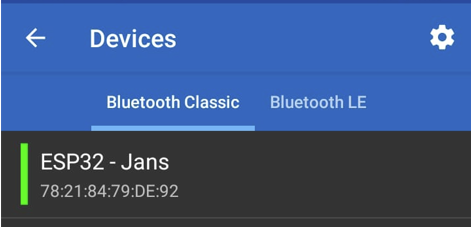
In order to make bluetooth communication between ESP32 and a phone, you should install an app in your mobile phone. Here are the complete steps to set up peer-to-peer communication over bluetooth.
Here are some snippets on ESP32 that plays key role for the bluetooth communication. Call bluetooth serial directive and create its object.
Then in SETUP, start the serial bluetooth communication
Even if in some wired/wireless communication, numerical value can be directly transmitted or received, I think it is best option to always send and receive them in CHAR/STRING form.
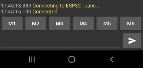
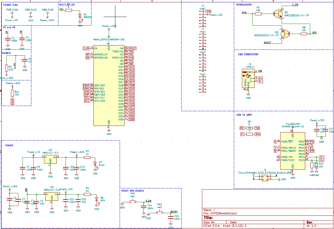
Here is the demo that shows how command can be sent over bluetooth serial from my mobile phone. All files involved in second project can be found on below link, I put enough explanation in them (I belive): ESP32 BreakoutI am planning to use wireless communication on my final project. It can be just data transfer using bluetooth, remembering that wired communication is not so strong in ESP32 and ATTiny3216, and data transmission using IoT for real-time reporting. So, I draw full schematic of my own ESP32 breakout where I already put SAMD11C microcontroller as programmer via TX/RX. UPDI is not supported in ESP32. But I proved that STM32 can be programmed using USB-Serial, hence SAMD11C can be used as well in ESP32. I will make the realisation later.
Schematic for ESP32 with SAMD11C programmer can be found below Alternative Pins for Communication We can use alternative pins provided by ATTiny3216 and ATTiny1614 if the original pins are used for other task. But remember they are just alternatives, not additional communication pins. I tested alternative pins for display (SPI and I2C), except the UART. |