February 2nd, 2022, the course continued talking about:
Raster and Vector image
Design 2D and 3D using opensource and commercial softwares
Delivering data type file for manufacturing
Some game engines
Knowhow on graphic simulation
The objective of weekly assignment are:
Students understand the differences between raster and vector image
Students familiarize themselves with one or two 2D and 3D design software
Students create objects with corresponding software
Students are able to proceed their design to rendering, animating, and simulating
Students provide progress of their potential projects using corresponding software
Learning Outcomes
After this course, I am able to
Explain the difference between Raster and Vector image
Use 2D CAD software to design an object
Use 3D CAD software to design an object
Render, Animate, and Simulate my design
Appropriately display the results (image and video) in this website
Start designing part of my potential final project
Raster and Vector Image
Briefly, raster image is an image consists of pixels represented by numerical values. These values can describe coordinates (pixel location), intensity, and/or else.
Raster image is a digital image. It can be a photo captured from analog camera then scanned or pages of your book then scanned. The digitalization of these images convert natural colors
into predicted colors. Raster image can be manipulated using various software, starting from simplest to complex. Those softwares can be an opensource of commercial.
When zoomed times and times, raster image will pixelate and the intensity difference amongst pixels will be murky. Take a look at below image that demonstrates it.
The image was zoomed and sliced on the nose, and it exhibits the lack of raster image. The solution is to provide bigger resolution along with the dot-per-inch (DPI). However,
it will increase size of the file (in Bytes).
Differ to raster image, vector image dos not contain pixels. They are mathematically generated. Their colors looks unnatural and beautiful. This type of Image
is useful for specific purpose like drawing logo, animation movies or clips, cartoons, etc. This kind of image is also useful for scientific publication. The difference between both image types
can be easily obseved by zooming in them. Raster image, when zoomed, will exhibit pixelation over the surface, while vector will mantain its solidity no matter how many time it gets zoomed. Take a look at
images below as comparison between the two.
2D Design Software
I use several 2D design software like Photoshop for photo manipulation, Coreldraw for cartoon creation, and Inkscape for lasser cutting and vinyl cutting purposes. I don't use much more software other than that.
Introduced
The GIMP
I am interested to dig an opensource software called GIMP. The installation software is available for Windows, Linux, and macOS. This software can be downloaded by clicking below image.
The installation in Windows is pretty easy. After the installation complete, I created new file and start drawing object related to my final project to help me learning about this software.
The Lemon Monitoring Robot will be drived with recharable batteries. The batteries I am planning to use is Lithium Ion (Li-Ion) 21700. One cell can provide 3.7 V 5000 mAh. Part of my robotics are planned to
have common 5 V voltage. So that, I put two cell Li-Ion in series to provide 7.4 V. Later, in my circuit, I am gonna have 5 V DC regulator to regulate appropriate voltage for my system. To stabilize their position when placed
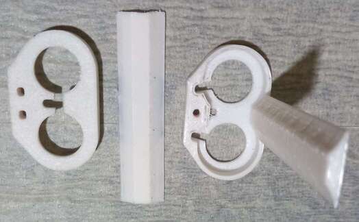
on robot, I place them in a holder made from PLA material (3D printed). In this holder, I also put BMS (Battery Management System) that can help the recharging process. The parts that I already printed is shown in image below.
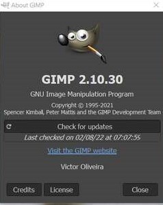
To simplify the object, I choose to redrawn part on the center as 2D image using GIMP. The version that I used was
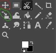
GIMP provides all image manipulation tools on the left side of the window. Since I used to use Photoshop, I felt unconvenient with this software. For instance, the tool for scaling (red circled) and moving (green circled) an object are distinguished which is weird
as shown by image below. I must click both tool consecutively, again and again, just to rescale and move the object which is wasting time. Also, the selection tool does not immediately fill either the inside or stroke of the object. However, I eventually managed to
make all of them functioning.
In this 2D raster sketch, mostly, I was using tools:
Move
Rescale
Crop
Gradient and Bucket Fill
Perspective
I avoided to use magic wand and scissors tool, as I found it less user-friendly. I also was working with so much layers to avoid losing previous works like selection and coloring. I took about an hour to sketch my 2D design from 3D object that I printed as part of my final
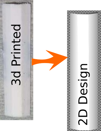
project. Here are the steps to create 2D design of 3D printed object from my final project:
Select Rectangular tool
Use this tool to create rectangular shape with width = 2 px and black stroke. Black stroke filling can be done by right clicking your mouse and select stroke path. Create new layer before the path stroke filling so you will have this stroke lay on the new layer.
Select Paths Tool
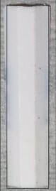
As it can be seen from original image that the surface is not flat. To do this, I did 2 things. By filling gradient color on the surface and put indentation path. To make the indentation path, use this tool by manually clicking points over the rectangular. This action will create new path
between two adjacent points. Then do right click and select stroke path and fill with white color. Usually, GIMP will use foreground color to fill this stroke/path. So you can just select white color as your foreground color.
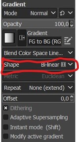
Select Gradient
To colorize inside the created shape of previous step, select gradient tool and select light-dark-gray as foreground color and white as background color. Then drag your mouse over the shape's surface. Please select bi-linear setting for this where you can find it on gradient setting.
This can be found on the left pane of the window.
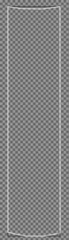
You may do the steps more than once according to my experience. Even it is far from perfect, the 2D design from 3D printed object that I prepare for my final project is shown below.
Tip
Always work with layers. Create new layer to place any changes on your design. So you can come back to that later when anything goes wrong.
New layer is created only when the selection or path creation is done.
Change your working area into new layer after the selection.
Do not forget to push [ENTER] on your keyboard whenever you want to release path tool (changing mouse back to normal).
The Inkscape
Differ to GIMP, Inkscape is a software for vector image manipulation. This software is easy to use yet powerfull. One can download the software by clicking image below.
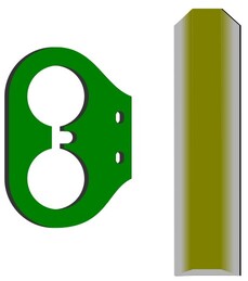
Actually I printed 2 parts with 3D printer to hold batteries for robot I am going to make for final project.
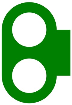
But one of this part is fractured because I did not carefully treat it when trying to assembly the battery and BMS PCB on the part. However, it can be useful to show shape of each part and redrawn it on Inkscape. Before everything is started,
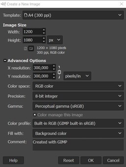
create a document and set-up the page setting from menu: [FILE]>[DOCUMENT PROPERTIES]. I prefer to work on landscape view with A4 paper and mm as measurement unit as shown below.
Then, steps here are steps to create 2D design of parts I mentioned above. Similar to the way I use GIMP, I prefer to create many layers and assign each object to different corresponding layer. This has helped me to have safe work in design.
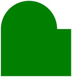
Body creation
I use this tool to create a rectangular as the body with the dimension is width = 30 mm and length = 20 mm. Any color will be good.
Outer circle
I use circle tool to create one circle at the top of the rectangular. The width and heigth of the circle is 24 mm. Any color will be good. I put the center of the circle exactly on the upper edge of the rectangular. To align them, I choose
from menu [Object]>[Align and Distribute]>[Align Left Edges] and the left edge of circle is glued to the left side of the rectangular.
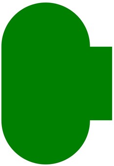
Duplication
Before the next process applied, I need to duplicate the circle to avoiding taking time to recreating it again.
Object union
Then hide bottom circle will leave you top circle with rectangular. Select the circle and rectangular by pressing [SHIFT] key on your keyboard, than go to menu [PATH]>[UNION]. The circle will join the body. After that, show bottom circle and
do the same. Both circle now join the body.
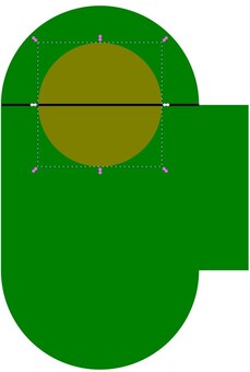
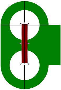
Inner circle
The part has two hollow parts in it. It can be done by putting two circles with same dimensional which is 15 mm. To make their position correct according to the body, I use line helper that i create using Bezier tool. This black-colored
line helper is used to make circles centered relative to boudaries of the body.
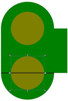
Object difference
To cut through the body using both circles, I clicked the circle one for every step with the body and applied object differences by selecting menu [Path]>[Difference]. It gives body with 2 flat hollows.
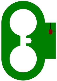
Hollow hub
These hollows have a hub that connect both of them. To do this, I create a rectangle with size of width 3 mm and arbitrary size of length (red-colored). Then use add other black-line helper to help positioning the rectangular. After that, I do object difference
between the rectangle and the body, just like what I did in the previous step.
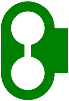
Another part to add that connected to the hub is added by using a rectangle. I create a rectangle with width equals to 2 mm and change all its corners to round by using edit path tool. Then I applied object difference to create another hollow connected
to the hub.
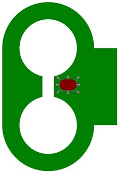
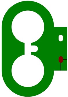
Last components to add are small rectangles close to right side of the body. Again I use black-colored line as helper to positioning the two small rectangles. These rectangles dimensionality are 3 mm x 2 mm. With the helper line, the objects position can fit the correct position relative
to the body. When they are fitted, then applied the object difference again.
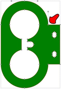
Body curving
The right side of the body should be curved. To do this, I click edit path tool then select the node shown by red-colored arrow. After that, I adjust the angle of rightmost node to get curvy shape. I did this to bottom side of the
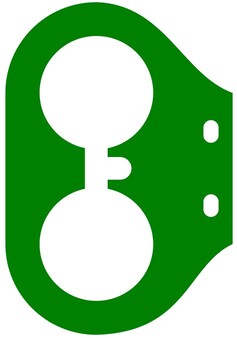
Final touch
As a final touch, I duplicate the final version after and change the duplicated version to black. Then I moved it to the bottom of the final version object by clicking lower selection to bottom tool that you can find easily on the panel control below the menu rows. By adjusting
the position of black object, I can get the shadow of final version object. I also add second part without further explanation to this result. This object is created with simple steps than the first object. It only used edit path and gradient tool. Gradient tool
can be found on the left panel along with other tools.
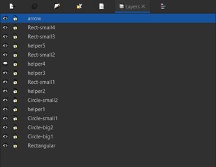
All layers
Here is all layers that I created when creating both objects. Just to inform you that for second object, I used only 1 layer to speed the design as it is intended merely for additional showcase.
Tip
Here are my suggestions when working with Inkscape
Always consider to use layers to safe your life.
The way I draw the object above can be done with different style to avoid using many helper.
Black-color helper line can also be replaced with Guide Line. This guide line is yellow-color straight line that you can pull down from top-ruler and left-ruler.
Measurement tool in Inkscape sometime does not match with the dimension of object. I tried comparing this, but I do not know which one is correct.
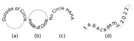
I also do some experiment with text. One of most interesting to me is that I can place text on curve that I make using tool like bezier. The step is simple as:
Drag bezier tool and draw some curve. I draw 3 circles and 1 random curve. With one of the object (or all) selected, go to menu [PATH]>[Object to Path]. The object(s) will be changed to Path.
Write any text you want and place them anywhere you want.
Then select your curve or object then continue with the text, then go to menu [Text]>[Put on Path]. Voila!!! You will have your text located on your object following its curve shape. You can see some of the demo below.
Text Manipulation
Some tips for you
You can use objects/shapes filled with colors as path to follow for the text.
You can make the path "dissapear" by selecting no-stroke in the Fill and Stroke option.
You can put text inside the objects/shapes by clicking Flip Selected Object Vertically by first selecting the object/shape (not the text). See this image below.
3D Design Software
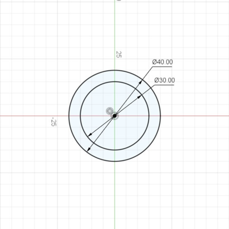
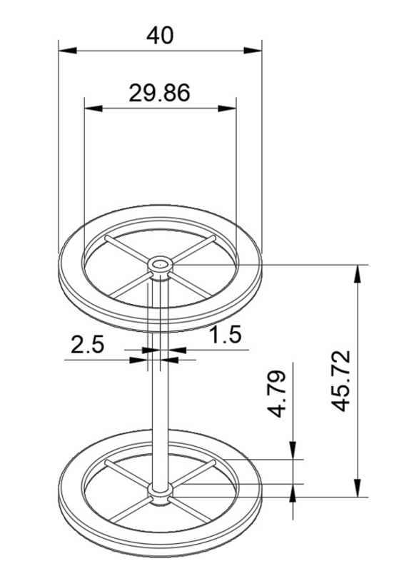
I frequently use Fusion360 as the software to help me design 3D object before printing. This software is popular and provides student version that help many students a lot for creation. In this weekly task, I make 2 wheels that connected by a road.
Nothing special with the wheels, which means they are just ordinary wheel. Theare 2 circles for each wheel used with radius 40 mm and 29.86 mm consecutively. The length of the rod 45.72 mm.
Fusion360
According to Autodesk, Fusion 360 is a cloud-based 3D modeling, CAD, CAM, CAE, and PCB software platform for product design and manufacturing. The benefits of using this software are:
Design and engineer products to ensure aesthetics, form, fit, and function.
Reduce the impact of design, engineering, and PCB changes and ensure manufacturability with simulation and generative design tools.
Directly edit existing features or model fixtures with the only truly integrated CAD + CAM software tool.
Other 3D CAD software which are frequently used by engineer and designer, especially the free software, are freecad. I learnt about Freecad, but still not familiar with it. The following steps are how to create 2 wheels that I mentioned above using Fusion 360:
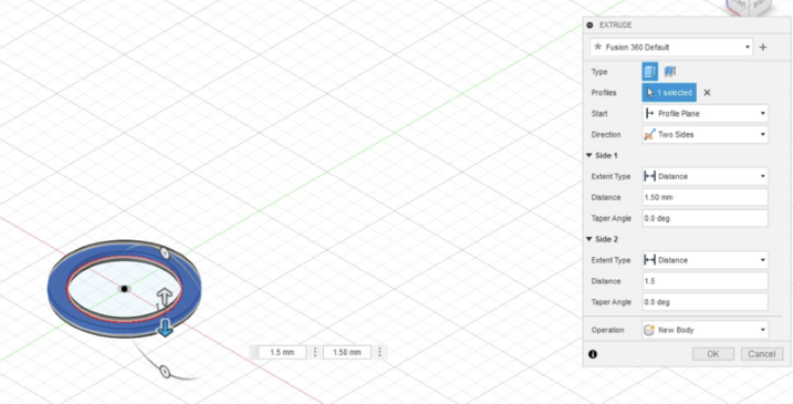
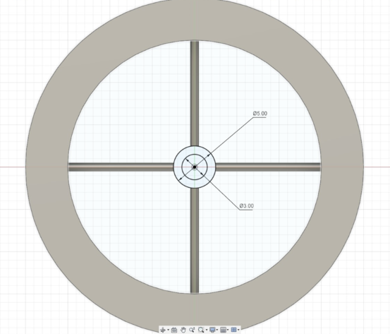
Make a circle object with certain parameters
Extrude the object
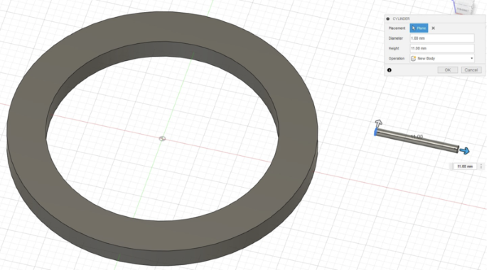
Then create a cylinder inside the circle (wheel)
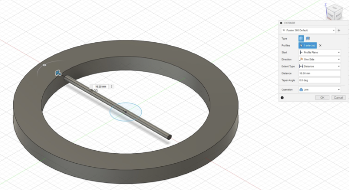
Use extrude with Cut to joint the wheel and cylinder
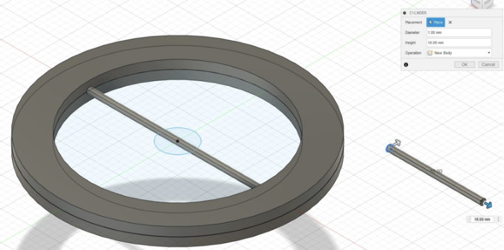
Add another cylinder so it will form plus symbol
Add circle on the center of the wheel using sketch
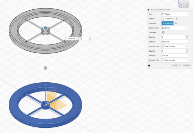
Copy the properties to get new exact wheel using Rectangular Pattern
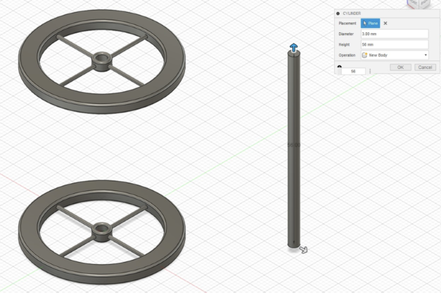
Connect both wheel using one longer cylinder
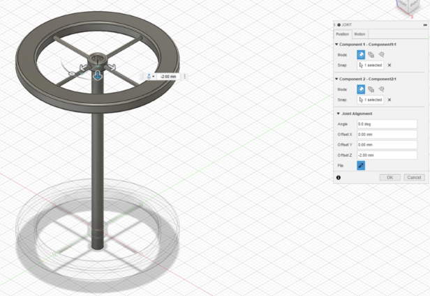
Then use joint to ensure that the cylinder sticking in inside the smaller circles on both of the wheel
Both wheel in the form of 2D diagram is shown below
One can add some "art" to them like fillet etc.
Render
When final object is done, it can be rendered in the same software as shown below
Animation
In this animation, I show how the joint between long cylinder sticking inside the smaller circles.
All files involved in this weekly task can be found on below link:
 Home
Home