Week 10 - Output devices
group page // repo source files // objectives
Contents
hero shot >
objectives >
- Linked to the group assignment page
- Documented how you determined power consumption of an output device with your group
- Documented what you learned from interfacing output device(s) to microcontroller and controlling the device(s)
- Described your design and fabrication process or linked to previous examples.
- Explained the programming process/es you used.
- Outlined problems and how you fixed them
- Included original design files and code
- Included a ‘hero shot/video’ of your board
files >
gold and brass >
well, not quite. I didn’t magically plate this PCB with gold or brass.
In Spongebob, Squidward makes a painting called Bold and Brash. The name I chose references this magnificent work.

design >
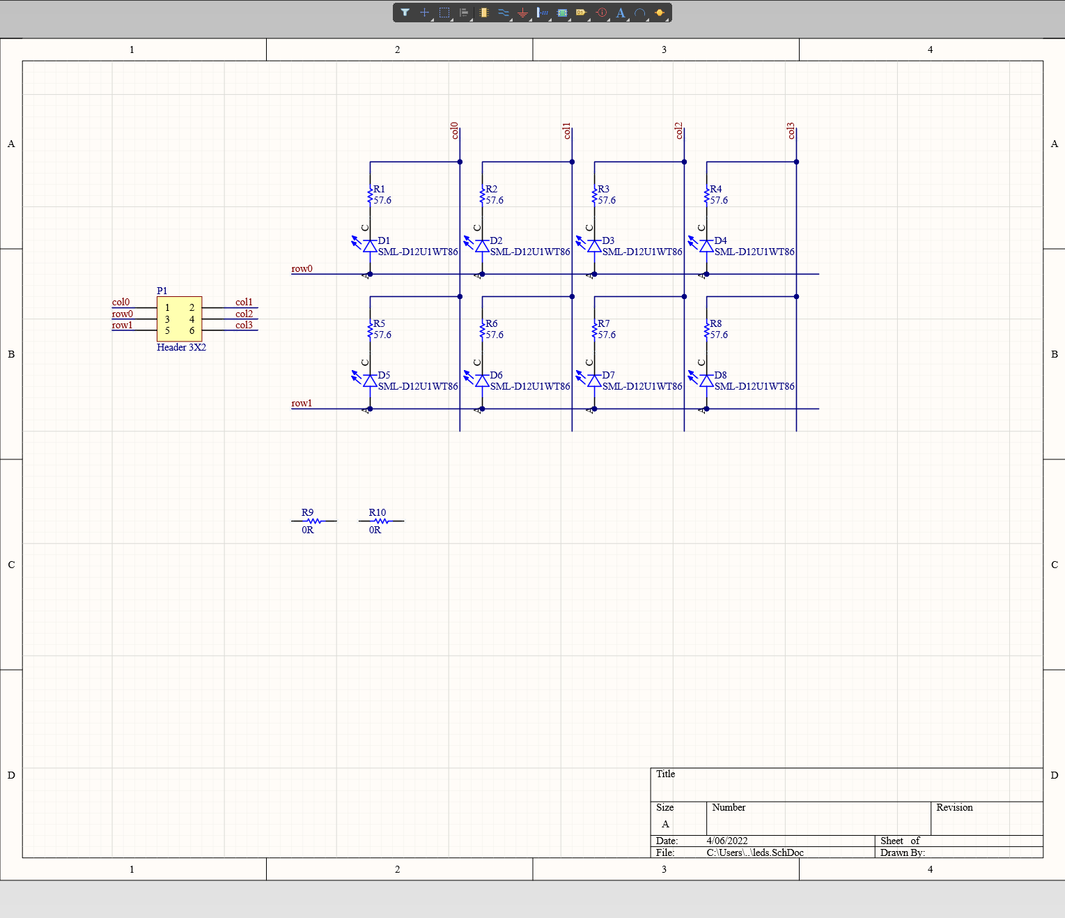
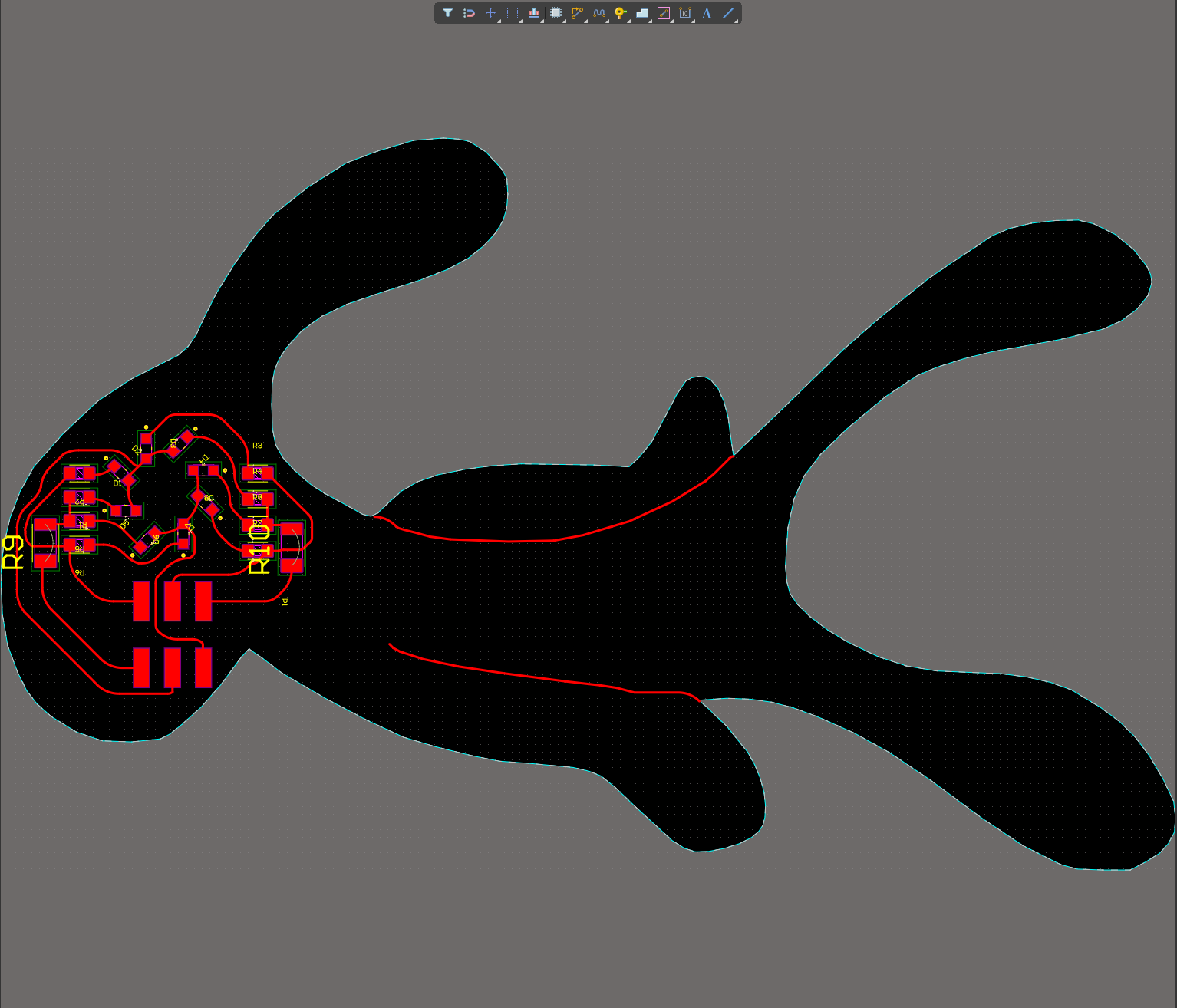
I was trying to implement a traditional multiplexed LED circuit (not charlieplexed, but I’ll probably do that next), and I deliberately made the circuit messier than normal to play around with commonly held preconceptions about how PCBs are supposed to look.
Also, seeing the “swoopy” circuits during a previous lecture inspired me.
Up until this point, I had been rectangularly fitting boards to the components as well. At work, I’ve done plenty of ecad/mcad integrated design, but I haven’t had a chance to express that for non-engineering reasons.
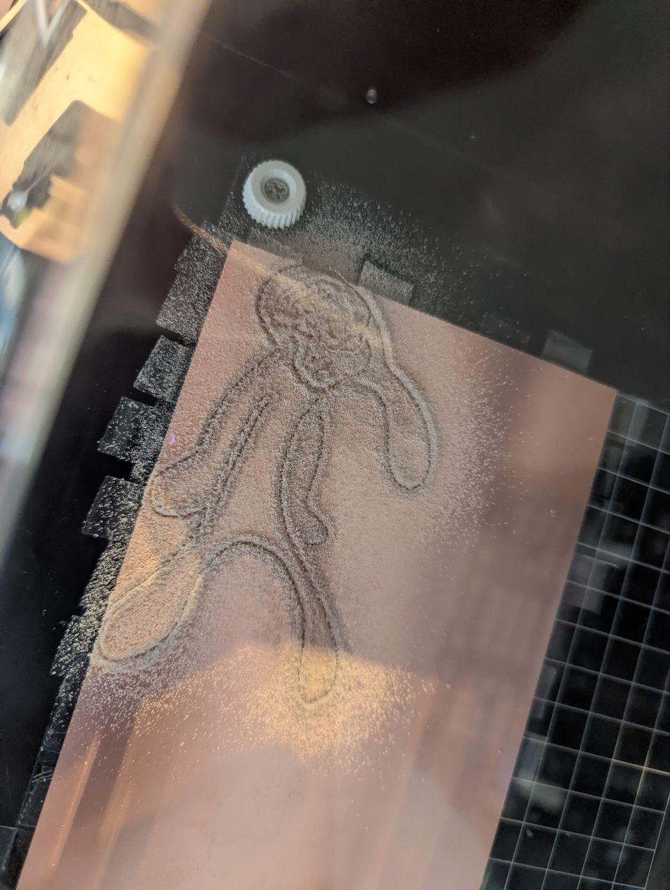
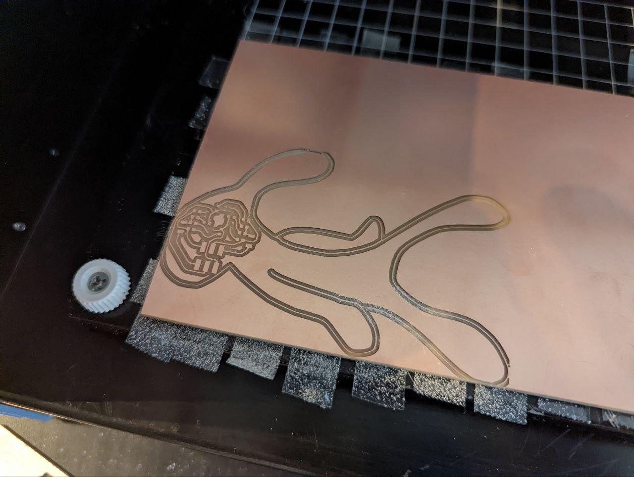
After I finished my board layout, I looked for a suitable outline to match. I started by searching for amoeba; I thought my trace layouts and components positions embodied that well.
However, I eventually gravitated towards Squidward. Probably a stray neutrino passing through the right neuron or something.
https://duckduckgo.com/?q=bold+and+brash+svg&kp=1&t=ffab&iar=images&iax=images&ia=images&iai=https%3A%2F%2Fi.pinimg.com%2F736x%2Fbe%2F5a%2F01%2Fbe5a01a87e6902910e9fbb59b4518701.jpg
As it turns out, someone already did some of the heavy lifting and traced Bold and Brash in black on white, perfect for converting into an SVG!

squidboard >
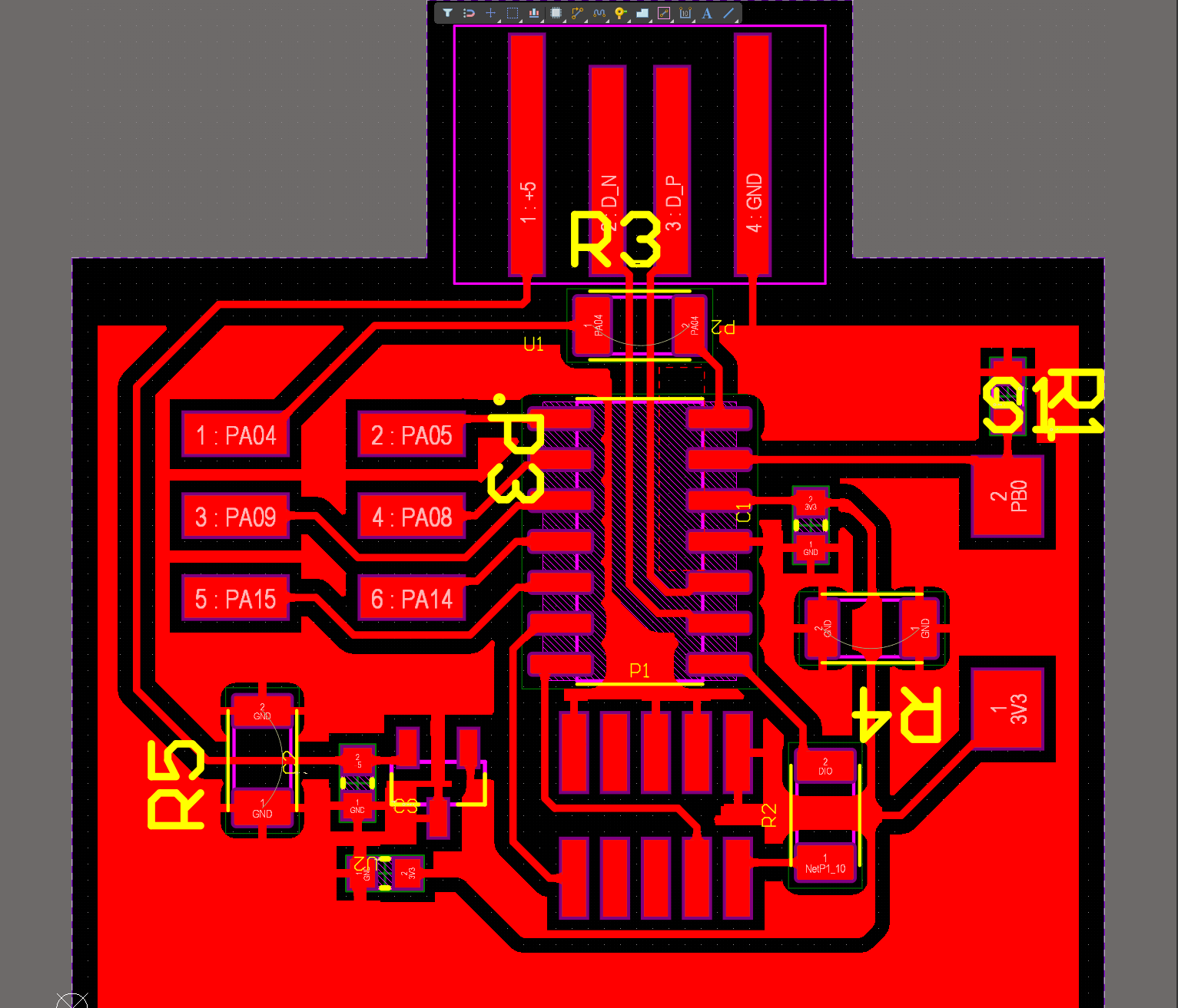
I’ve stocked up on a reasonably sized quantity of fab inventory components to expedite the progression of efab spirals. I’ve been having to work jumpers into my design paradigm, since I’m used to adding board layers to my PCB instead of jumper components to my SCH. Learning to use them seamlessly has been a work in progress, but I think it’s going pretty well!
I definitely saw it as a barrier to using the MDX-20 liberally for practical 1-layer PCB prototyping.
If you look at all of the schematics I made for this week, each one has a couple of 1206 jumpers (the resistors that don’t appear to be connected to anything in the schematic). This Altium Doc describes how to setup a library part to act as a jumper.
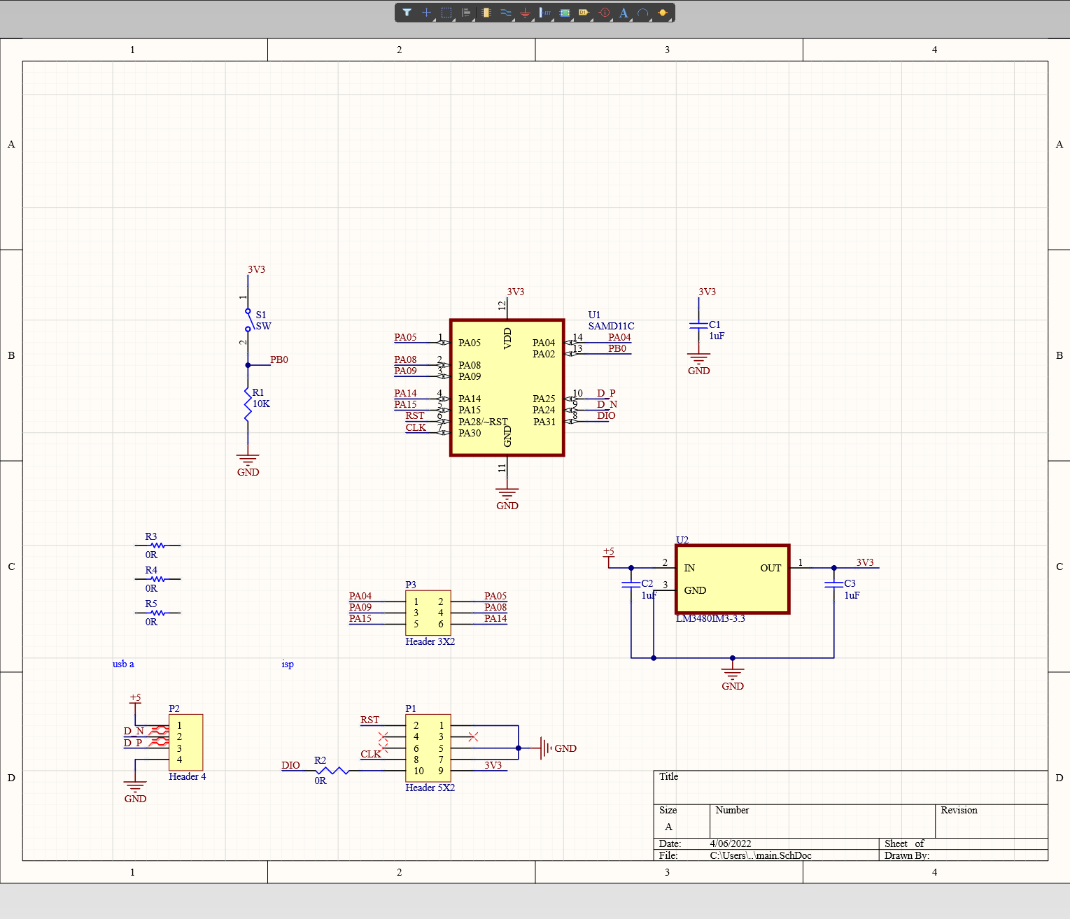
samd11c >
epaper dev board >
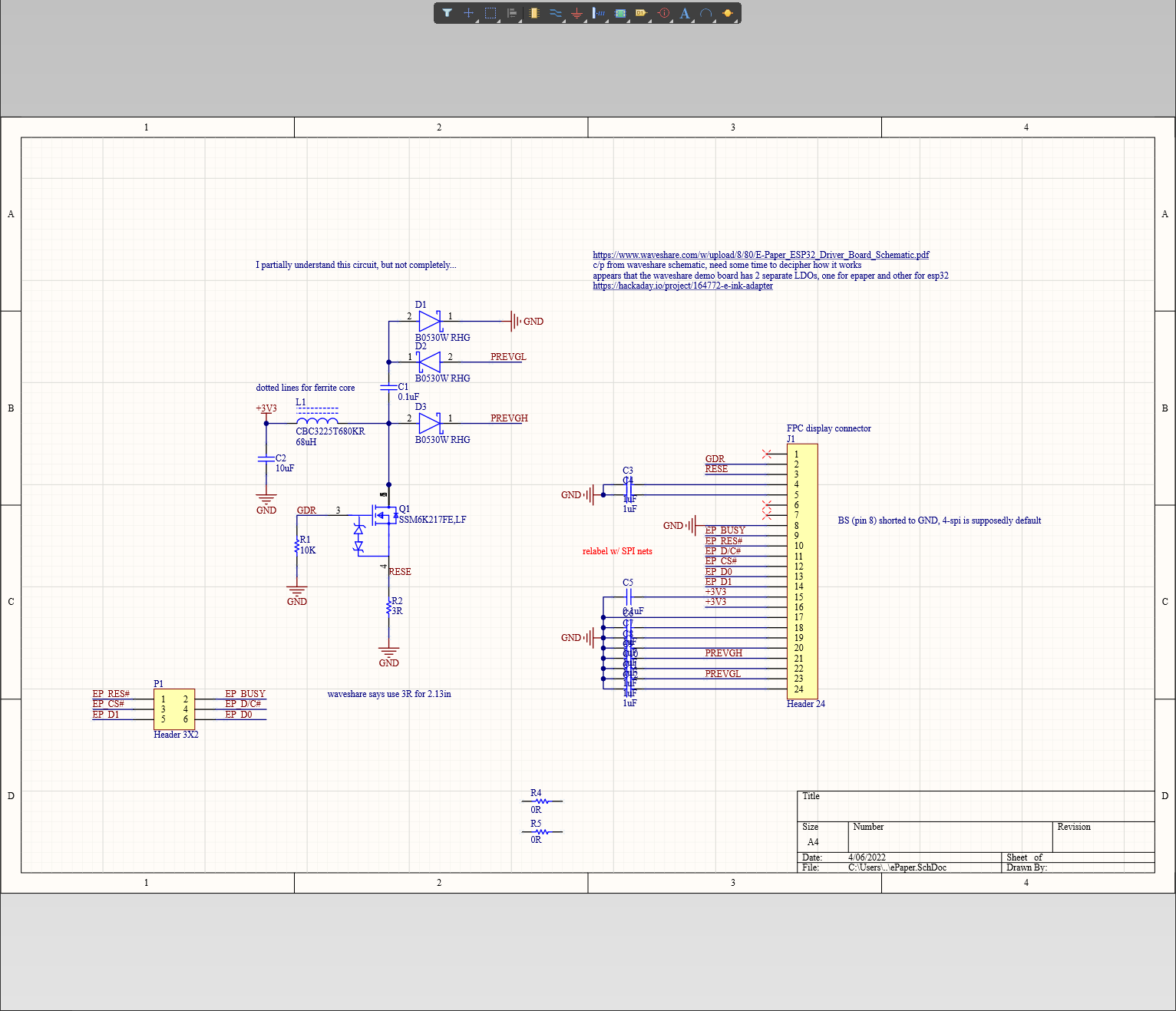
I wanted my second spiral to be for an epaper display I obtained awhile back in preparation for my wristLogger final project. One of the barriers I’ve been facing for prototyping the final project is the tiny clearance between pads for parts.
I’ve been meaning to run some tests with the 10mil bit to partially solve this problem, which I did this week using some guitar picks as an excuse.

efab >

soldering >
I had a bum LED in my squidward’s eye, so I used the diode function on my multimeter to check if the LED was burnt out or I had a cold (or nonexistent) solder joint. Turns out the LED wasn’t properly soldered down. However, after a couple of attempts at fixing the solder joint in place, I tried another approach and removed the LED. I added a lot of solder to both of the joints (the pads were too small; seems like the tool path sauntered off the beaten path here), and managed to create a bed of solder for the pads to stick to.
I also had a trace that was too close to the top of Squidward’s head, and was machined off during the outline pass. I jumpered it with some jumper cable. I’ve been trying to understand the relationship between the outline pattern in the mods PCB workflow and the finished board, and I think I finally figured out that mods likes to make an inside cut when provided a board outline. To compensate, you can modify the value in the offset block in the mods workflow, or you can add the appropriate offset in your ecad source files themselves.
For a 1/32in bit (~0.8mm), you’ll need to add 0.8mm per side. Assume the bit is traveling on the inside of the contour using the outline as a guide.
sw >
I’ve pretty much always used intelligent LEDs (of the neopixel variety) for my LED projects, so I’ve never really had to explore multiplexing or charlieplexing LEDs. I decided to start with a multiplexing design instead of charlieplexing, so I can compare the different approaches myself after implementing them.
I used the Arduino IDE for burning the micro (I want to start merging edbg into my workflow). My program is written in C (with Arduino library flavoring). The workflow is a bit clunky; programming using edbg would be a marked improvement since
In my code, I made a simple sequence using for loops to ramp up the duty cycle of my LEDs, keep it at a high duty cycle for a moment, then ramp it down again. This way, the user can see how duty cycle affects persistence of vision.
I first tested my code on an Arduino Nano, since I had some issues getting a samd11c chip bootstrapped during embedded week.
I managed to get my samd11c chip working (turns out the chip I was using a few weeks ago might’ve been a dud), but didn’t have time to figure out pin mappings… randomly connecting the col/row pins, I managed to get one LED to display the same behavior.
group >
measuring current >
I obtained a usb multimeter awhile back ~Nov 2020, which I forgot about! I’ll need to keep it closer in mind from now on; tools that don’t get used might as well not exist.
Based on measurements from plugging the Gold and Brass board into the usb multimeter, current draw appears to be anywhere from ~9 to 14mA. Since the multimeter is reading 5.12V, the wattage is anywhere from ~46mW to 71mW.
LED architecture comparisons >
As I’ve mentioned already, I’m accustomed to using intelligent RGBW LEDs, typically called neopixels. Although I only had enough time to implement a traditionally muxed LED circuit here, there are a variety of ways to drive/control LEDs. Non-exhaustive list:
- single-wire intelligent LEDs (neopixels)
- each LED addressable w/o additional components
- less cost effective compared to dumb LEDs
- pcb routing is much simpler
- multiple form factors (small leds, right angle leds, flex substrate, etc.)
- unless intelligent LED has redundancy (like ws2813), a single dead LED could compromise entire chain of LEDs
- driver ICs
- dumb LEDs w/ driver IC, single channel
- BCR420U is one example
- One driver can be responsible for driving a single or multiple serial chain(s) of LEDs of same properties. If multiple, chains are driven in parallel
- driver IC outputs high voltage, low current. Voltage drop over multiple LEDs in serial means required forward voltage over a single LED
- dumb LEDs w/ driver IC, multi-channel
- like single channel LED driver IC, but a single chip can control multiple channels, which can be used to selectively control individual LED(s) to create a display
- cost effective way to scale large (like, sculpture or advertising display large) LED works
- makes it easier to control for even lighting, Mike Harrison goes into more detail
- Mike Harrison gave a comprehensive talk on large LED works from the 2019 Hackaday SuperCon
- dumb LEDs w/ driver IC, single channel
- multiplexing
- traditional multiplexing
- 2n pins required to drive n^2 LEDs
- straightforward, a lot of keyboards use this technique
- not very cost effective, inefficient fanout compared to other techniques
- charlieplexing
- n pins required to drive n^2 - n LEDs, so more fanout efficient than traditional multiplexing
- layout is more complex than traditional multiplexing
- traditional multiplexing
A major part of decision making between different architectures is driven by the granularity of control required in the application and whether the required fanout can be achieved between the choice of microcontroller and additional driver ICs, FETs, etc.
Power is also a major factor. A single GPIO pin can supply ~10s of mA, which is sufficient for an LED or two. However, we quickly run into walls with more LEDs. Driver ICs and FETs are critical for delivering and regulating required power.