Electronics Design
Electronics Design
-
Group assignment:
- Use the test equipment in your lab to observe the operation of a microcontroller circuit board (in minimum, check operating voltage on the board with multimeter or voltmeter and use oscilloscope to check noise of operating voltage and interpret a data signal)
- Document your work to the group work page and reflect on your individual page what you learned
-
Individual assignments:
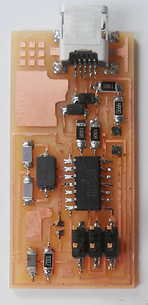
- Redraw one of the echo hello-world boards or something equivalent, add (at least) a button and LED (with current-limiting resistor) or equivalent input and output, check the design rules, make it, test it. Optionally, simulate its operation.
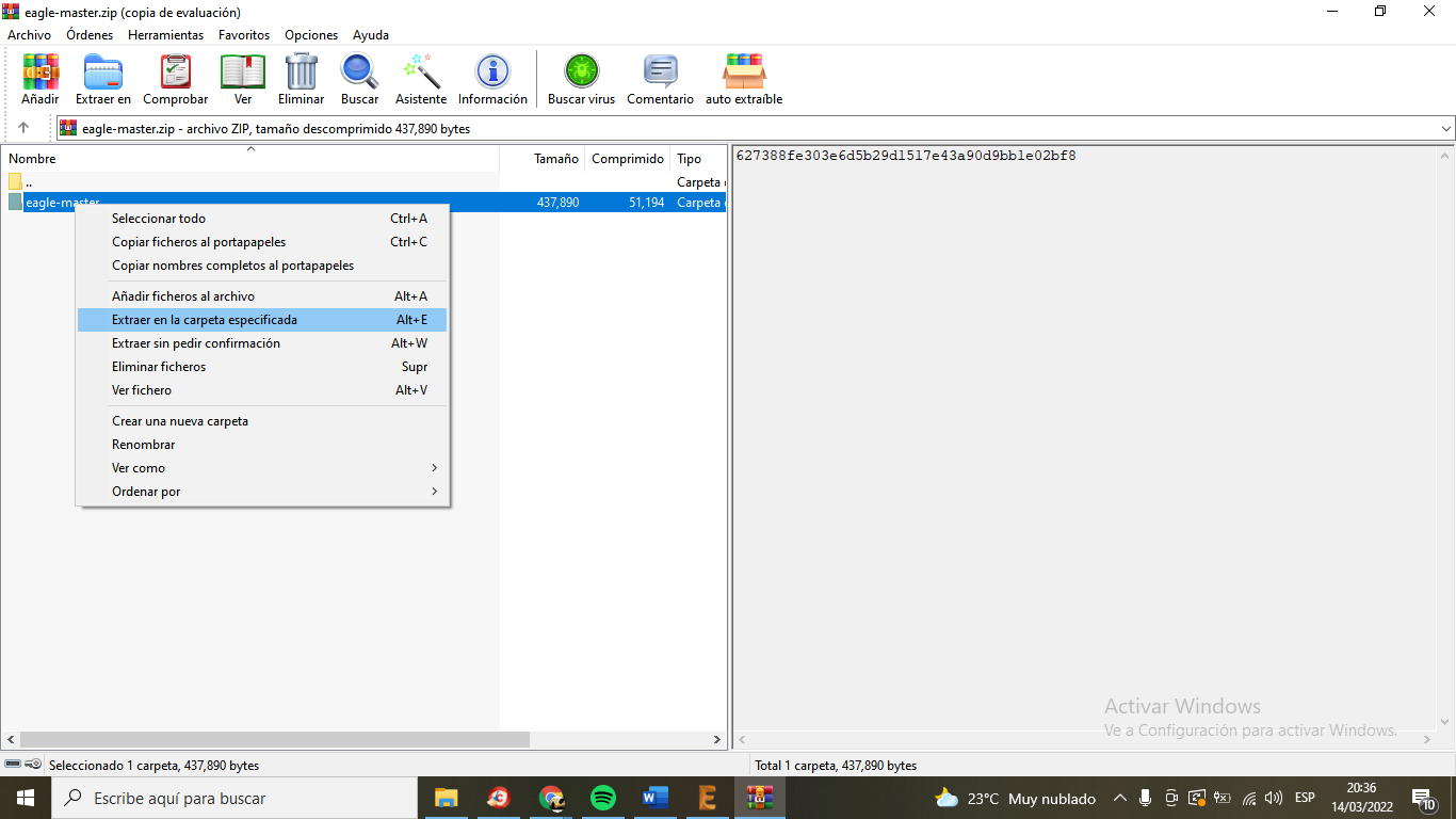
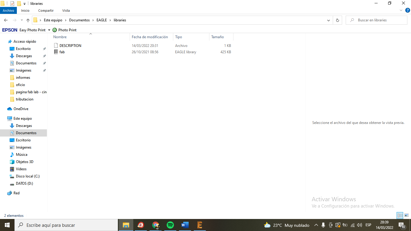
We don't have a fab lab yet... but we learned how to design our ready-to-cut electronic card... I'll show you a little of what Jorge, the instructor, taught me...
Here I will describe the step by step... of my learning... I thank my instructor for the
patience....
I put some links, which were my guide ...
- http://academy.cba.mit.edu/classes/embedded_programming/index.html#programmers
- http://archive.fabacademy.org/archives/2016/doc/programming_FabISP.html
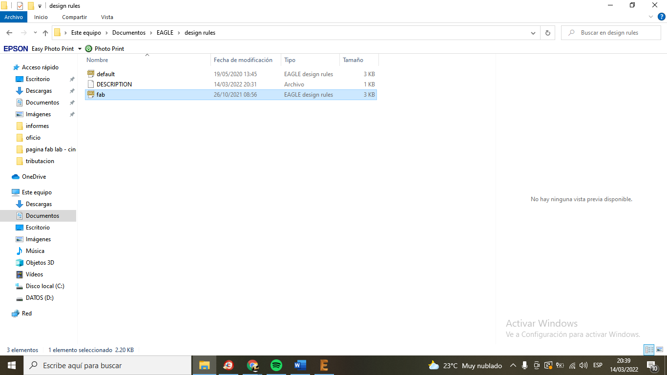
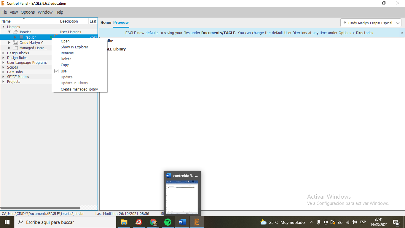
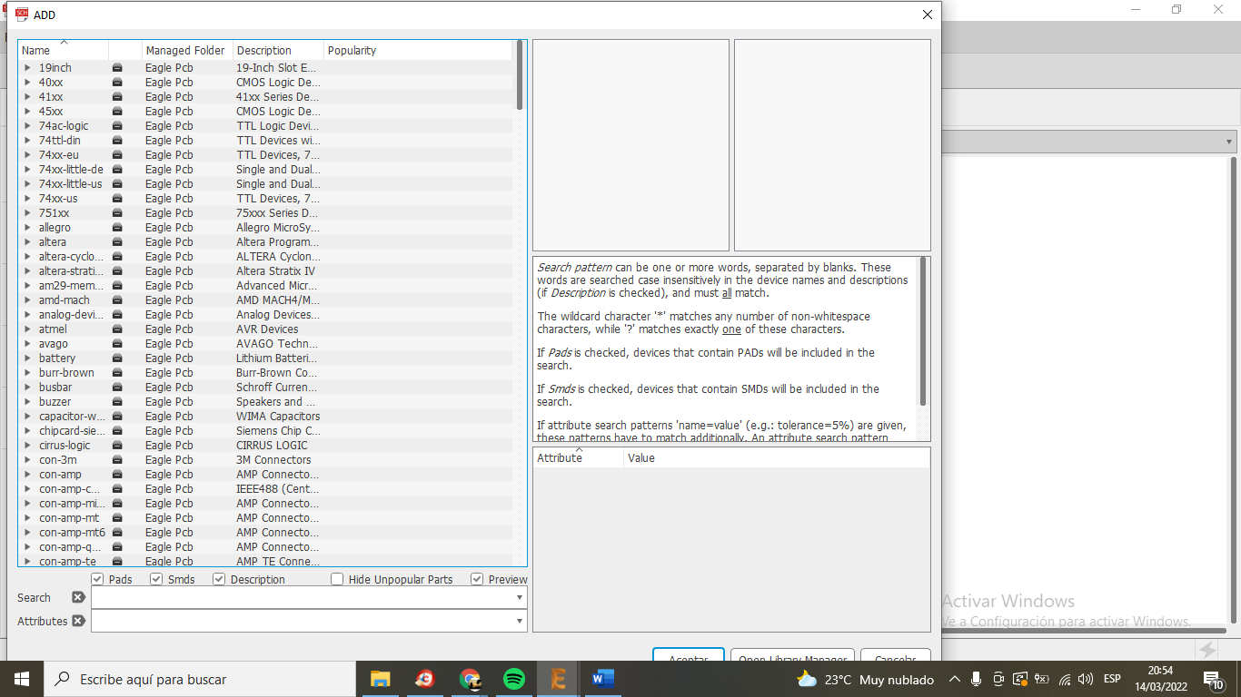
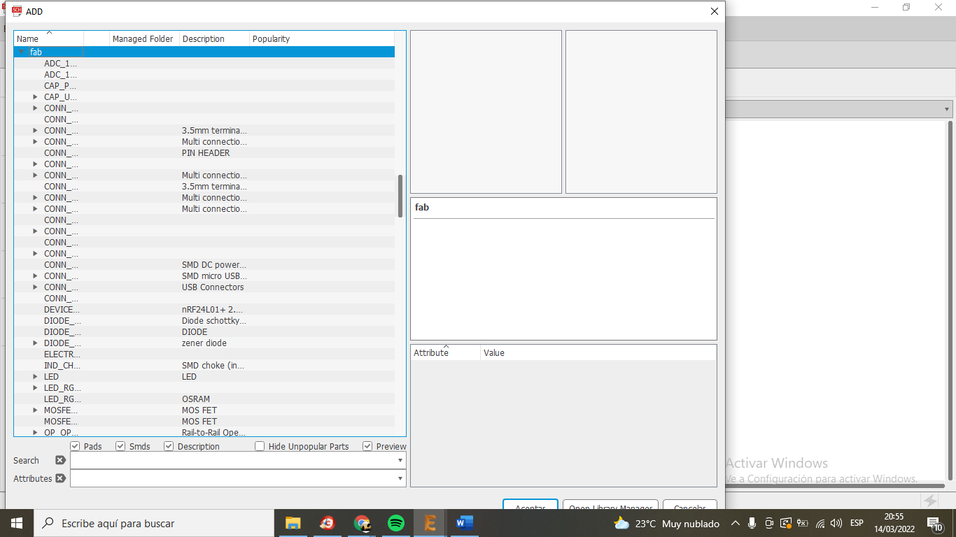
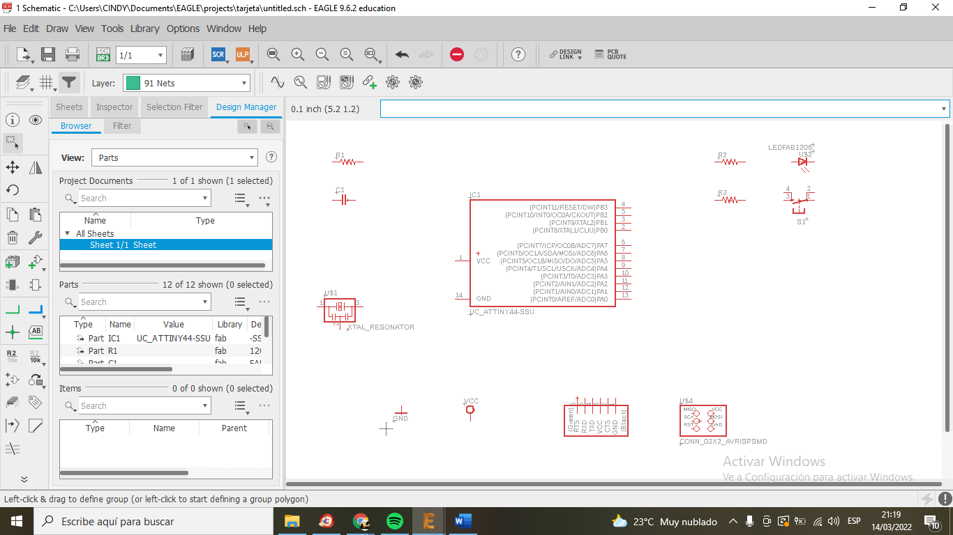
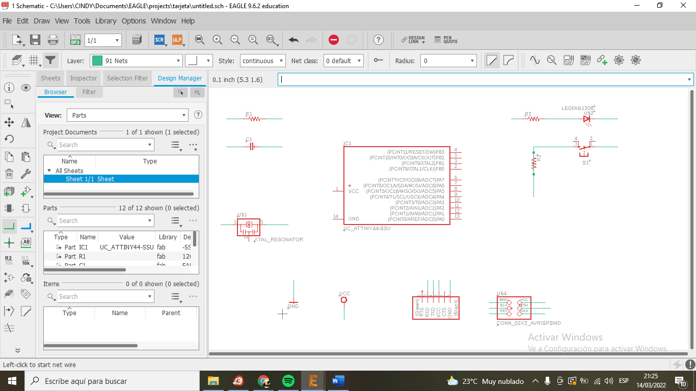
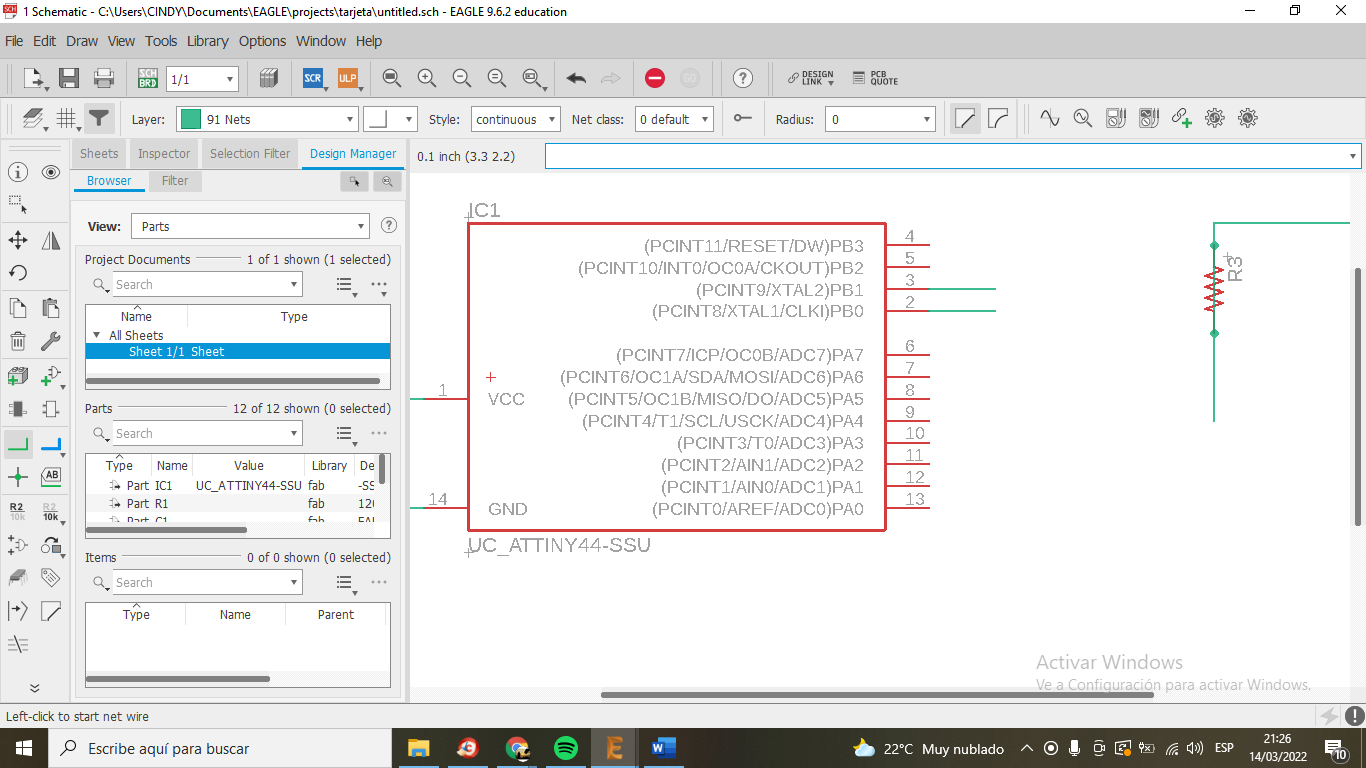
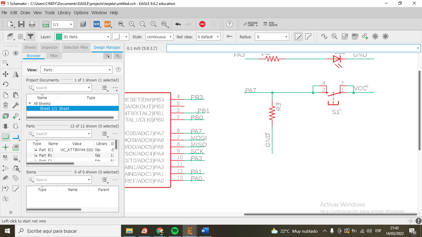
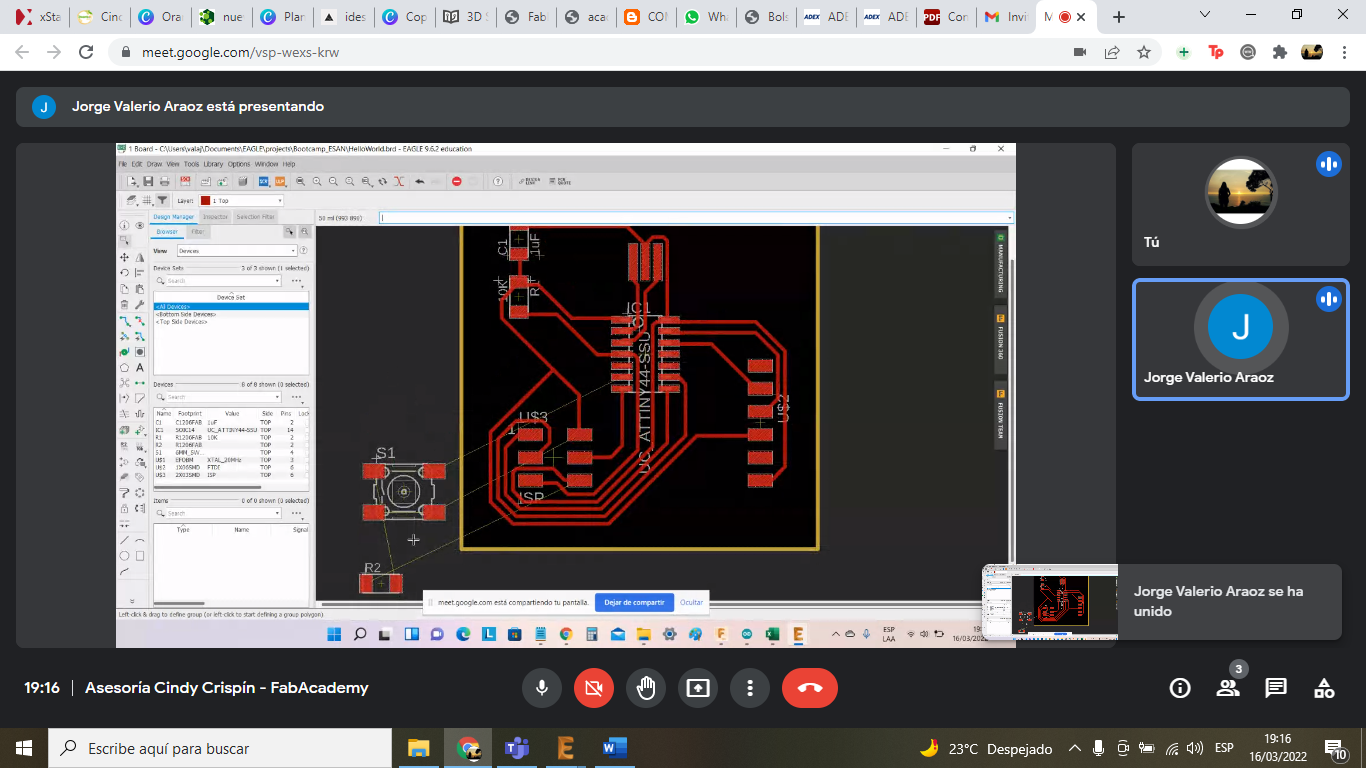
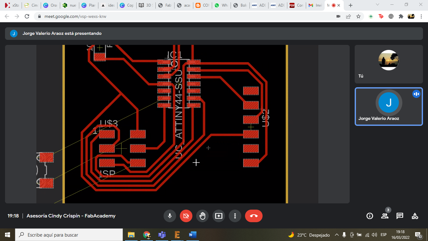
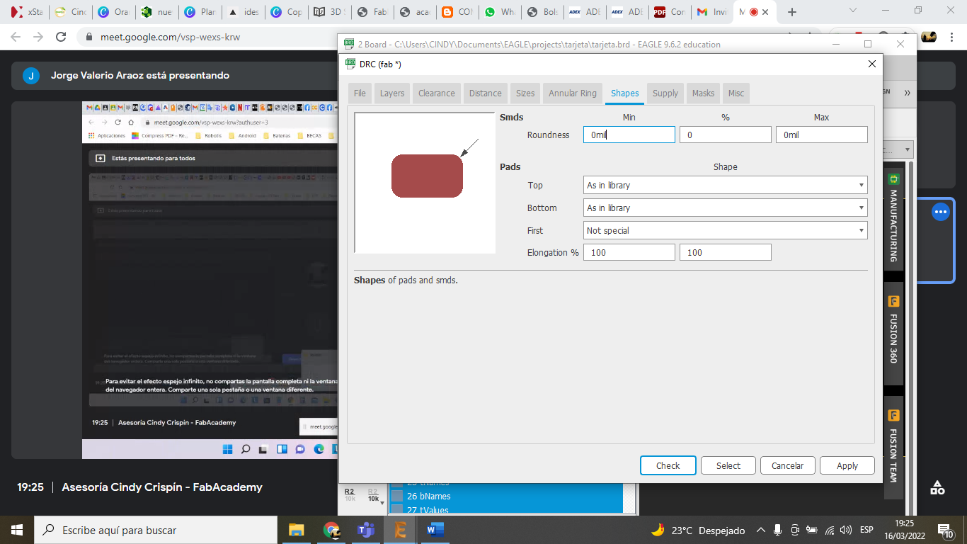
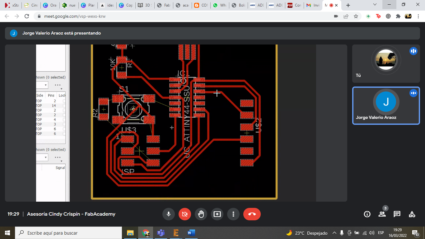
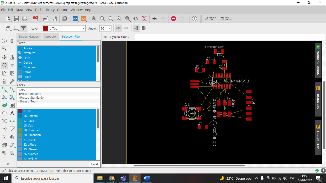
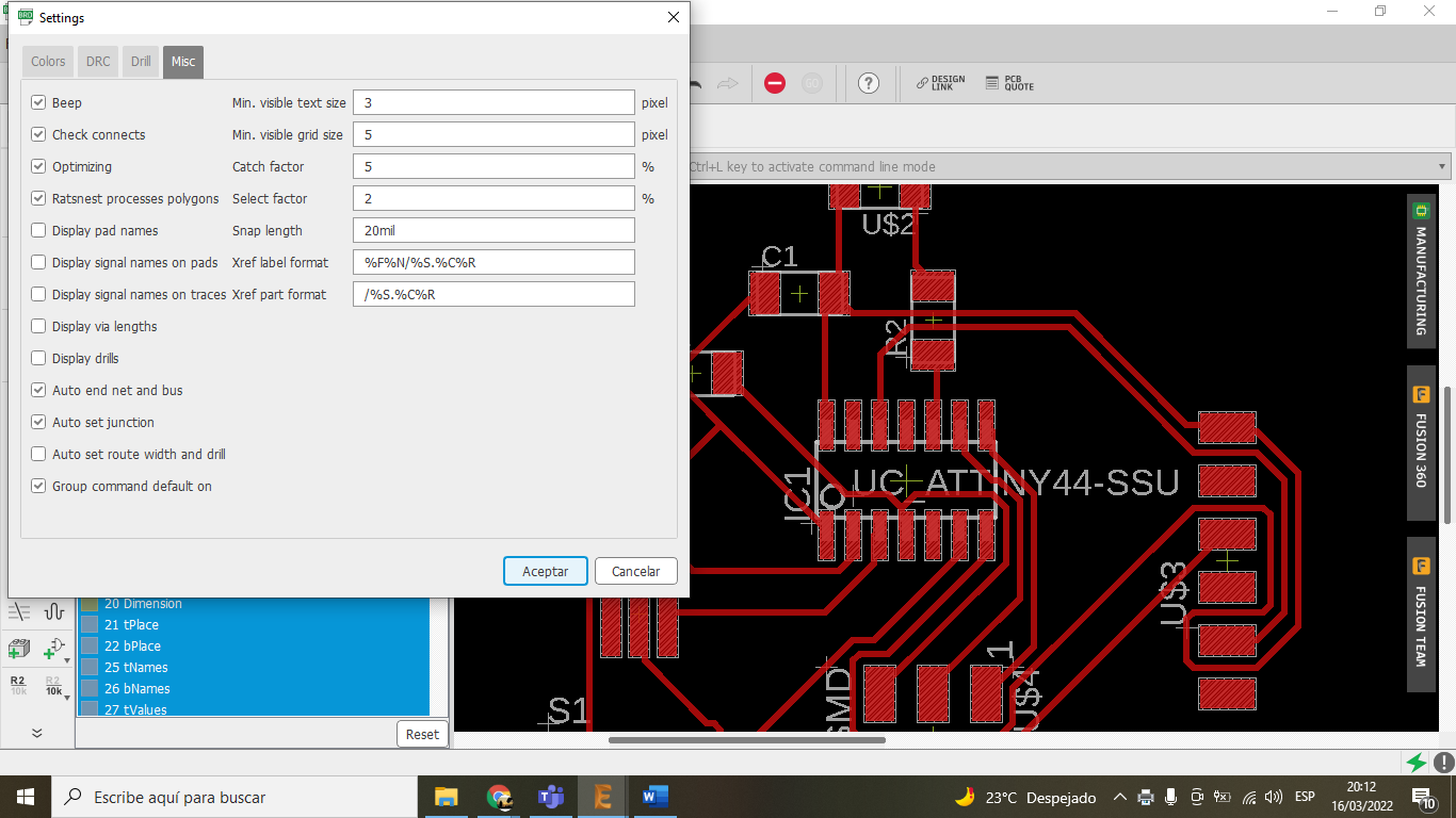
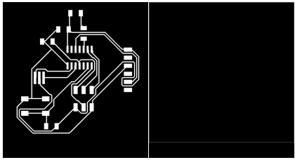
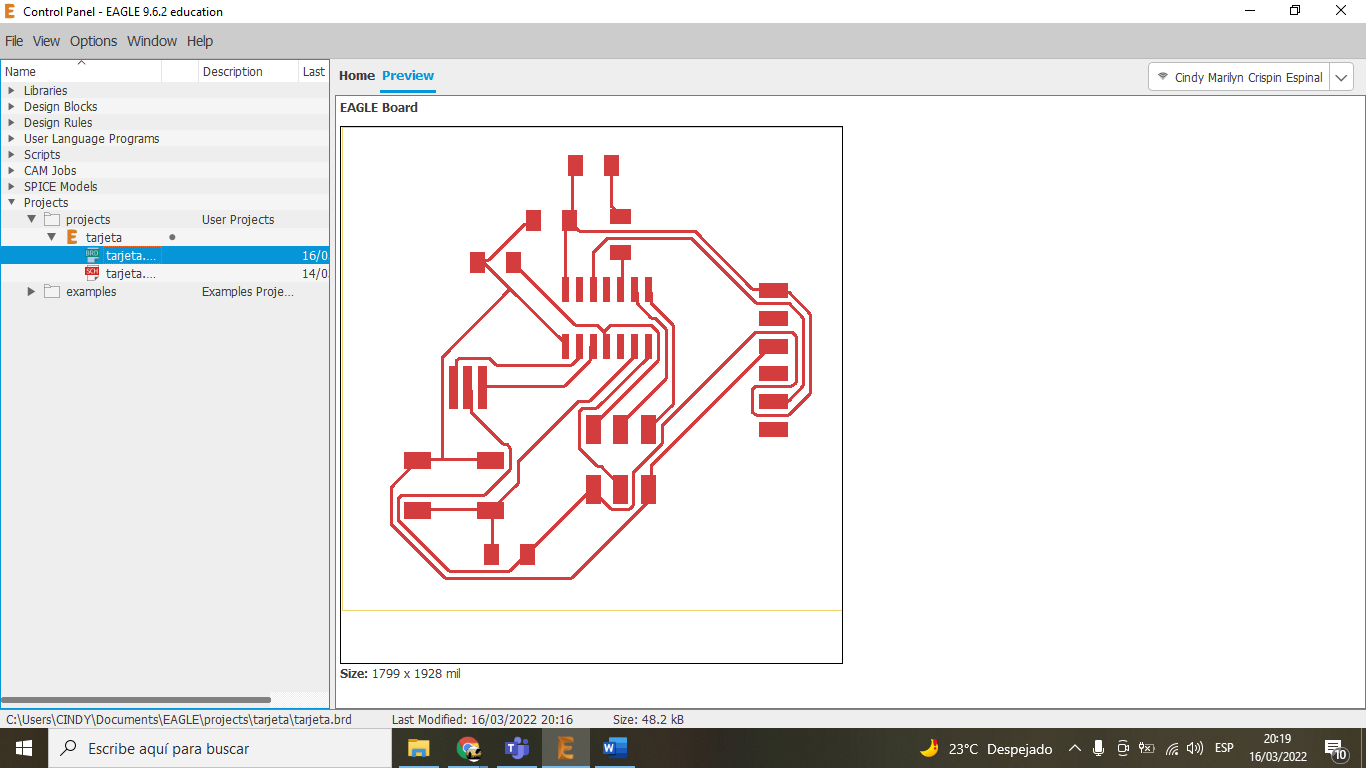
During this week, I learned to design a custom PCB from scratch. I used the Hello Echo board as a reference and added a push-button and an LED. The design was done in Eagle following the Fab Academy design rules.
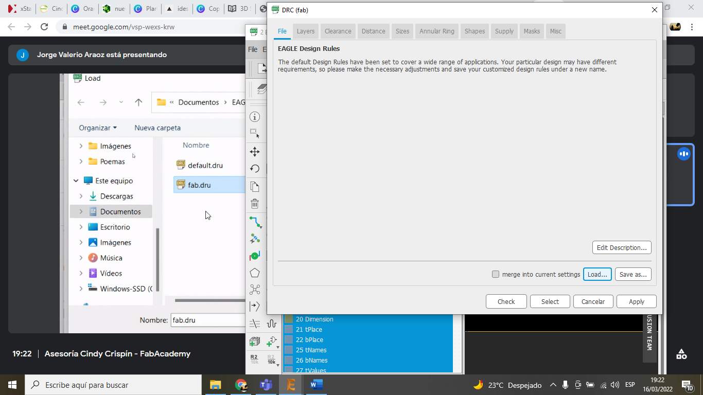
Technical considerations:
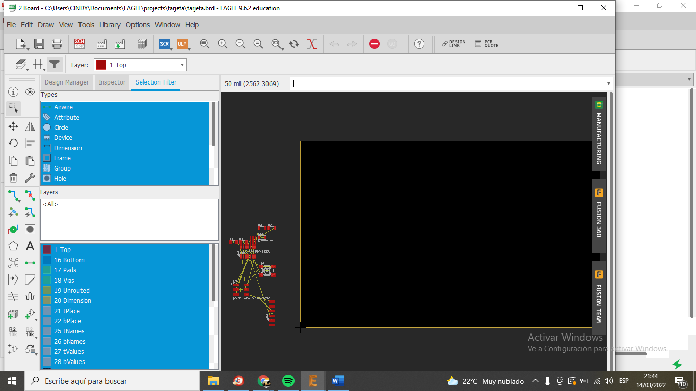
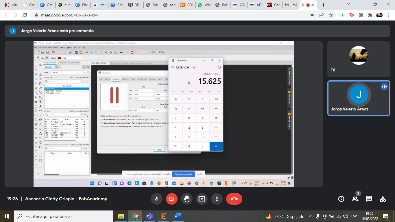
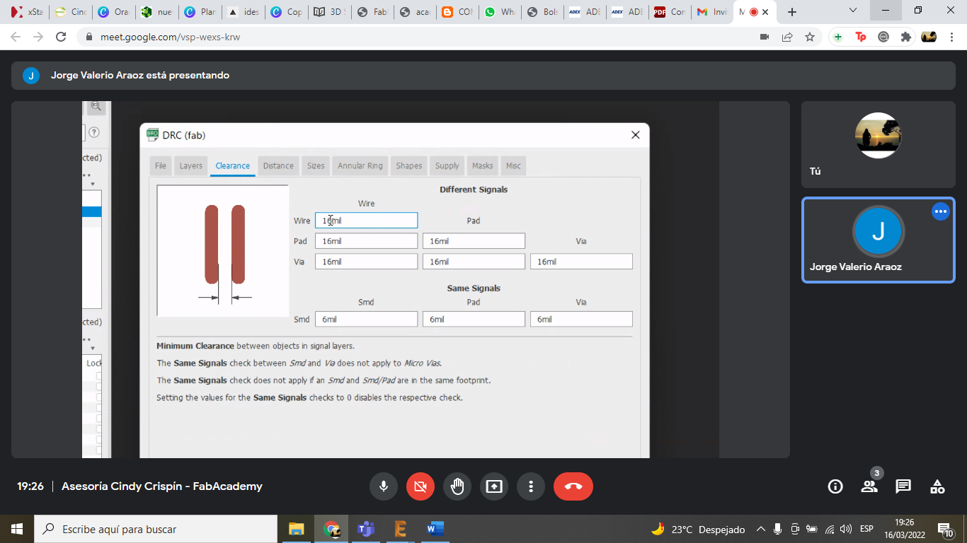
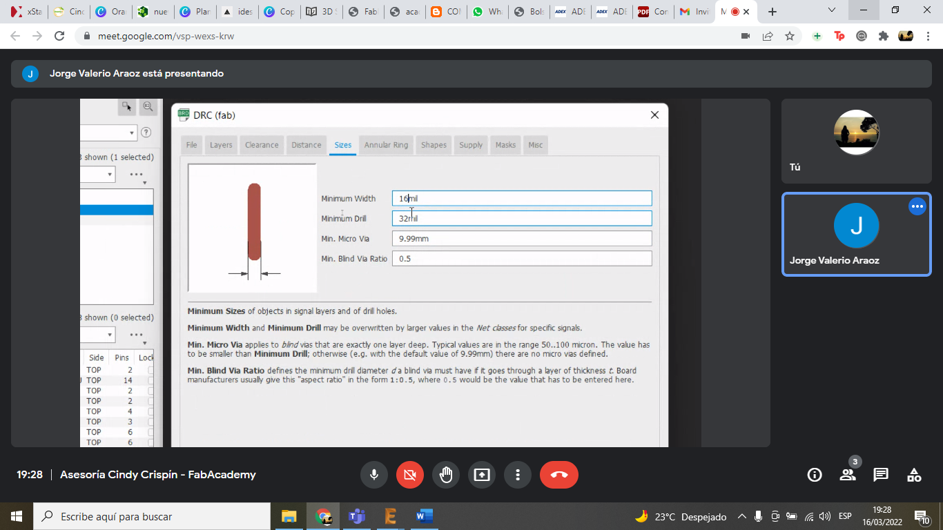
- Track width: 16 mil to ensure reliable milling with a 1/64" end mill.
- Clearance: 16 mil to avoid short circuits.
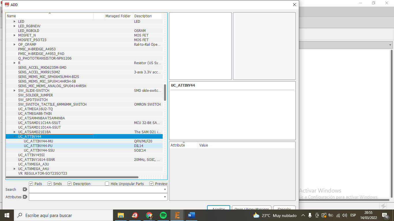
- Components: ATtiny microcontroller, resistors for the LED, and pull-up resistors for the button.
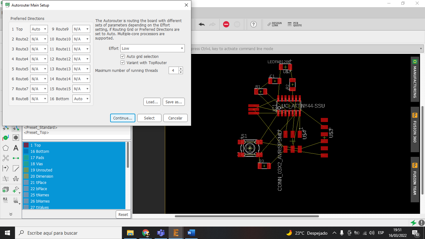
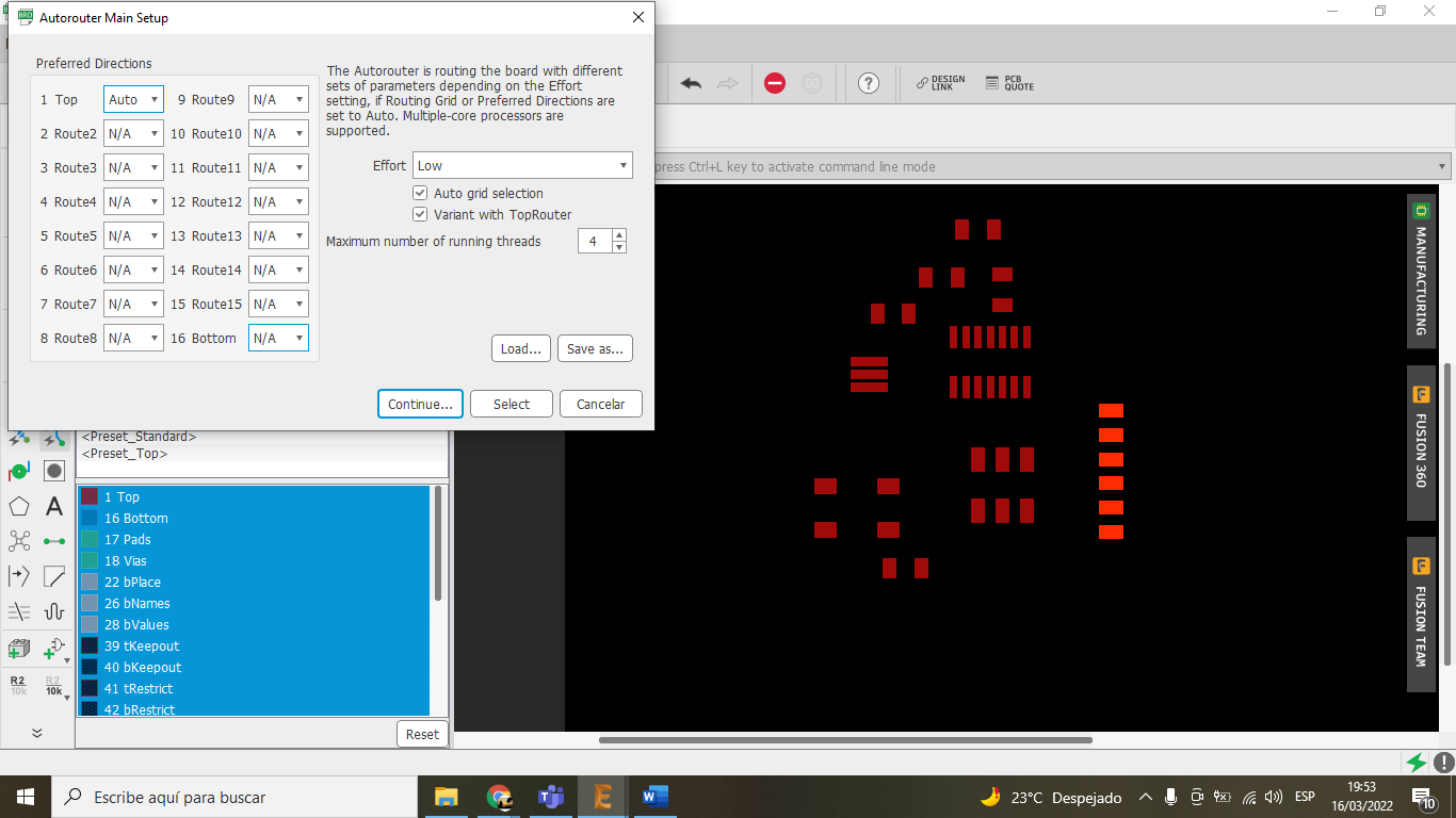
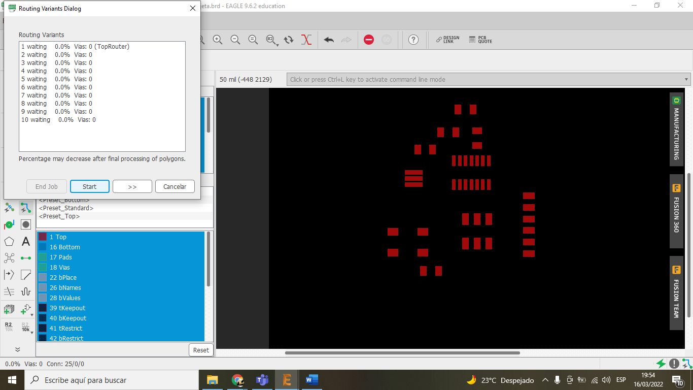
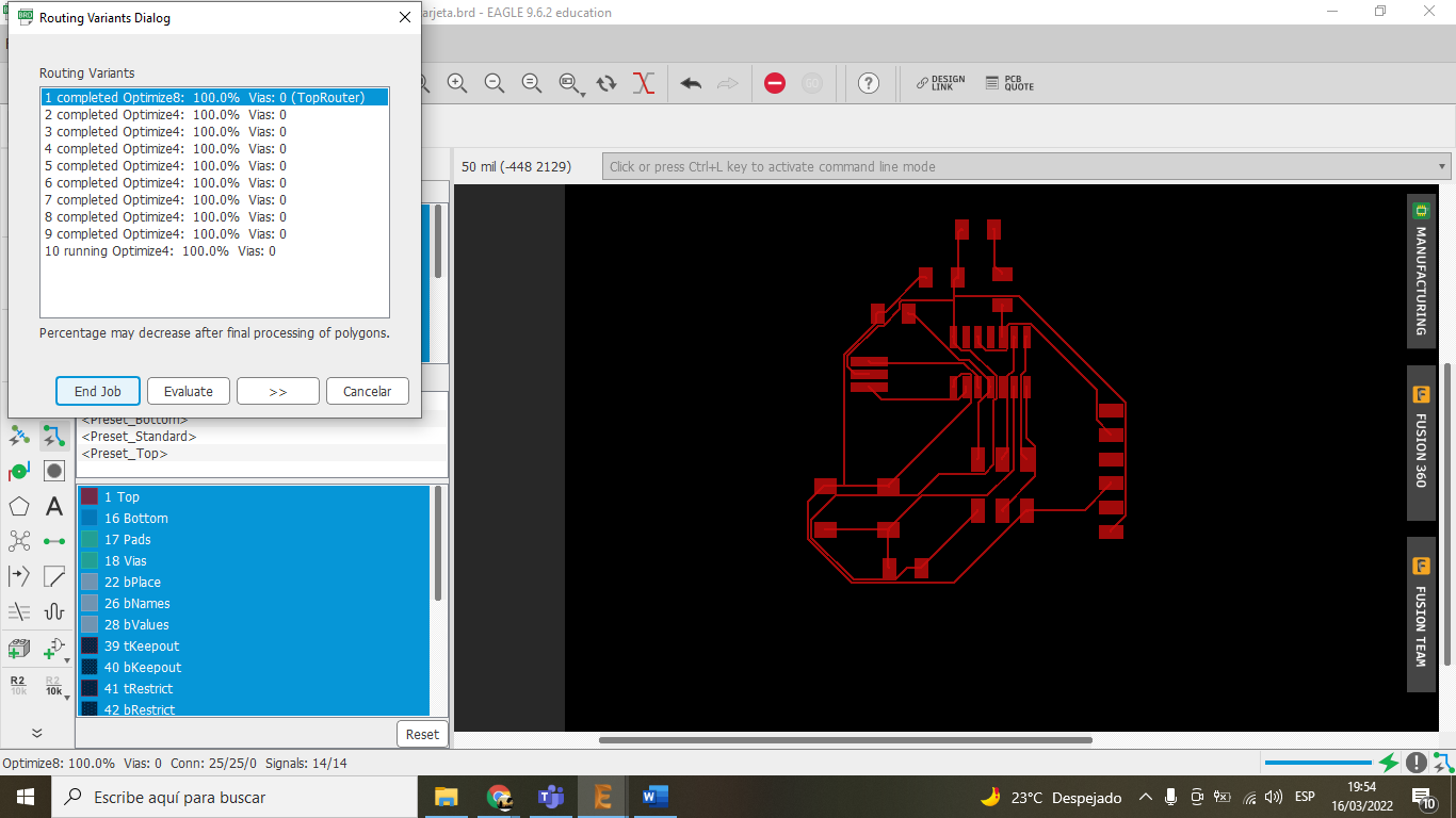
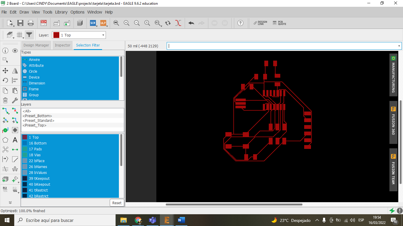
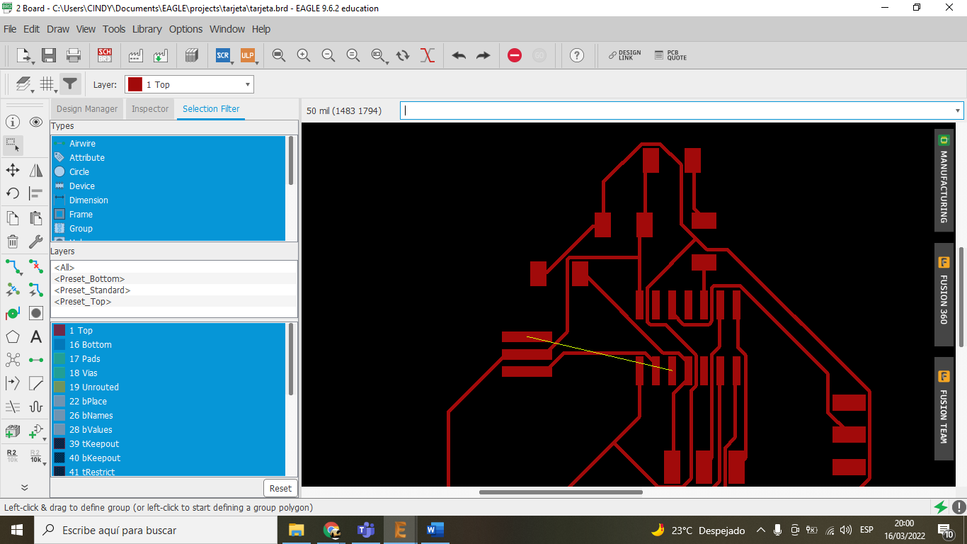
I started by creating the schematic, ensuring all nets were correctly named and connected. Then, I switched to the board layout and manually routed the traces to minimize the board size and avoid using jumpers.