Computer Controlled Cutting
Computer Controlled Cutting
-
Group assignment:
- Design, lasercut, and document a parametric press-fit construction kit, which can be assembled in multiple ways. Account for the lasercutter kerf.
- Cut something on the vinylcutter
-
Individual assignments:
- Characterize your lasercutter's focus, power, speed, rate, kerf, and joint clearance.
- Document your work to the group work page and reflect on your individual page what you learned.
Vinyl
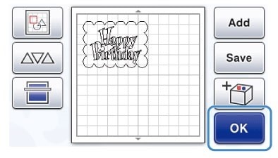
I started by selecting the image that I was going to put on the slicer. The picture is the Huando Institute sales logo.
This image was made in Inkscape, the image is saved in my file to be used when we have our machinery in the institute. Both images were converted to their respective bitmap.

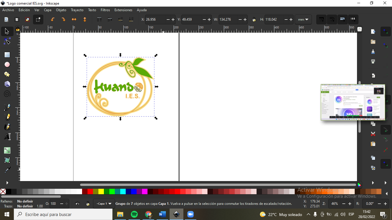

These images will be used to cut out and be decals and then used for various images.
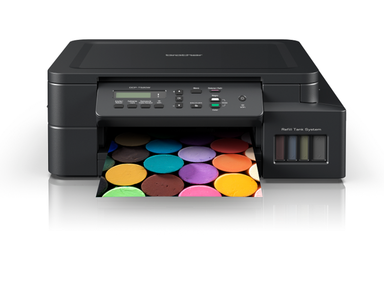
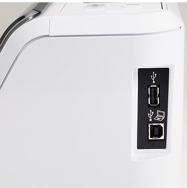
The PMSUB, will provide us with a machine to be able to make our designs to cut vinyl, it also allows us to scan a drawing and cut it instantly using different materials.
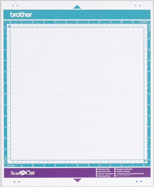
Some configurations for different types of grid mat.
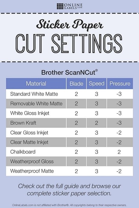
I will use a standart size.
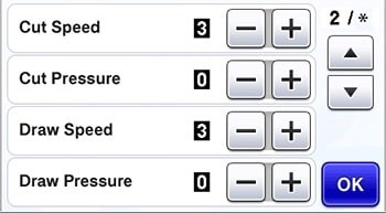
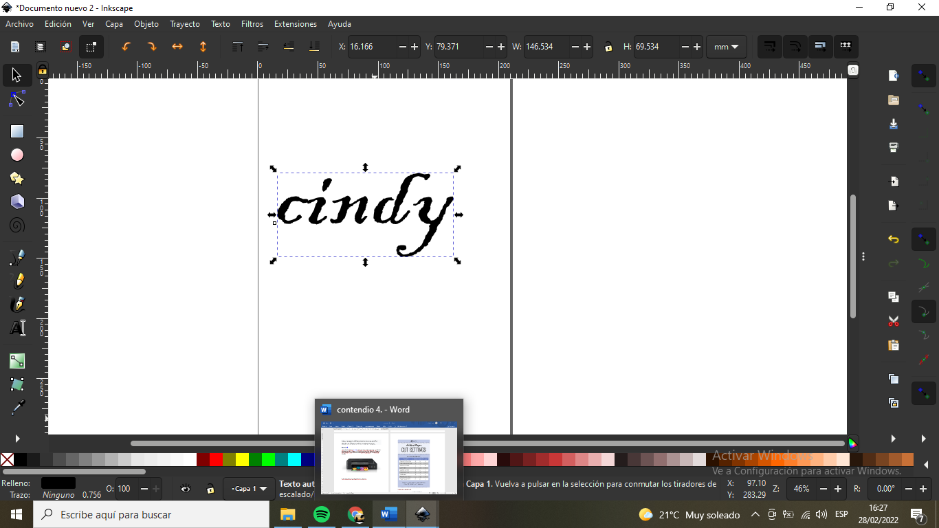
Well, in this part, I have learned that the machine that performs vinyl cutting... will cut all the lines of the image, even if the lines are canceled by other lines.
For best result, the drawn image should have only the outer lines and they should be connected and there should be no loose spaces.
To characterize the laser cutter, we performed several tests to determine the optimal focus, power, speed, and kerf. We used a standard speed/power grid to see how different materials react.
The kerf is the amount of material that the laser removes. By measuring 10 squares cut in a row, we determined the kerf to be 0.15mm.
We also tested the focus height using the "ramp test". This ensures the beam is perfectly focused on the material surface for the cleanest cut.
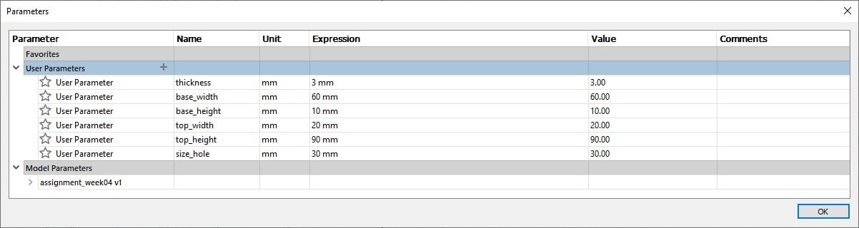
In this design, we worked with MDF material to create a parametric press-fit kit. I designed a bunny-shaped table for children. The key was using user parameters in Fusion 360, so that the thickness of the material (e.g., 3mm or 4mm) can be changed instantly without redrawing the entire model.
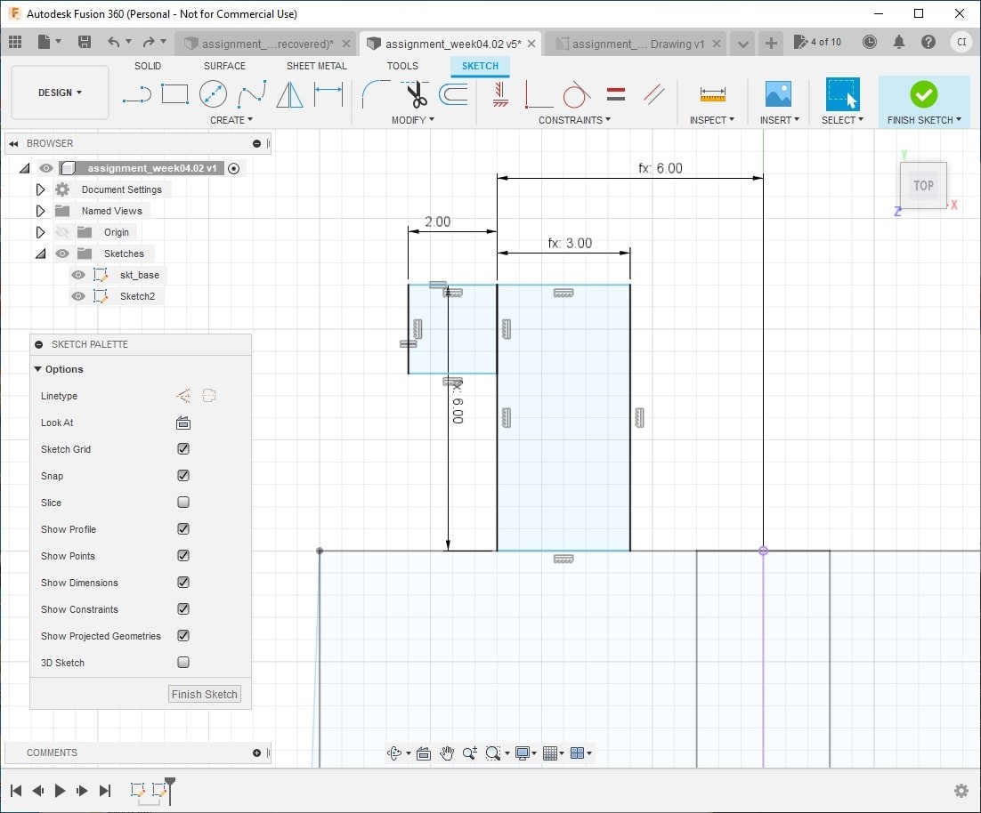
Each joint is a "snap-fit" design. I accounted for the 0.15mm kerf by subtracting it from the slot dimensions. The final assembly is solid and doesn't require glue.
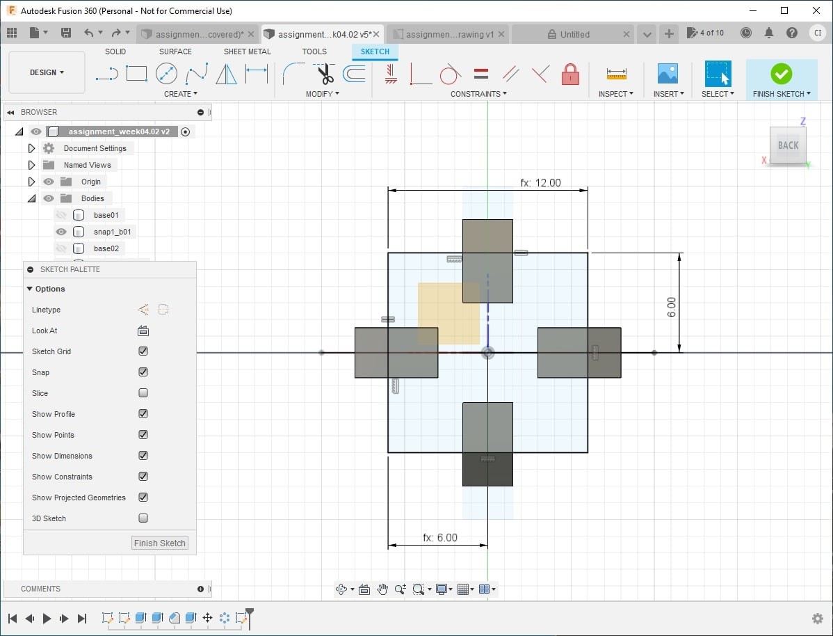
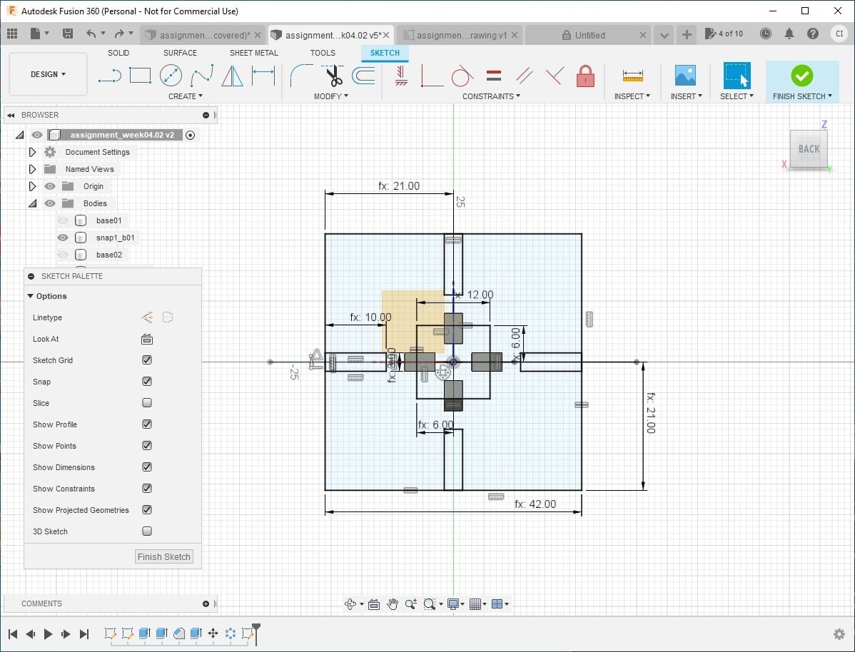
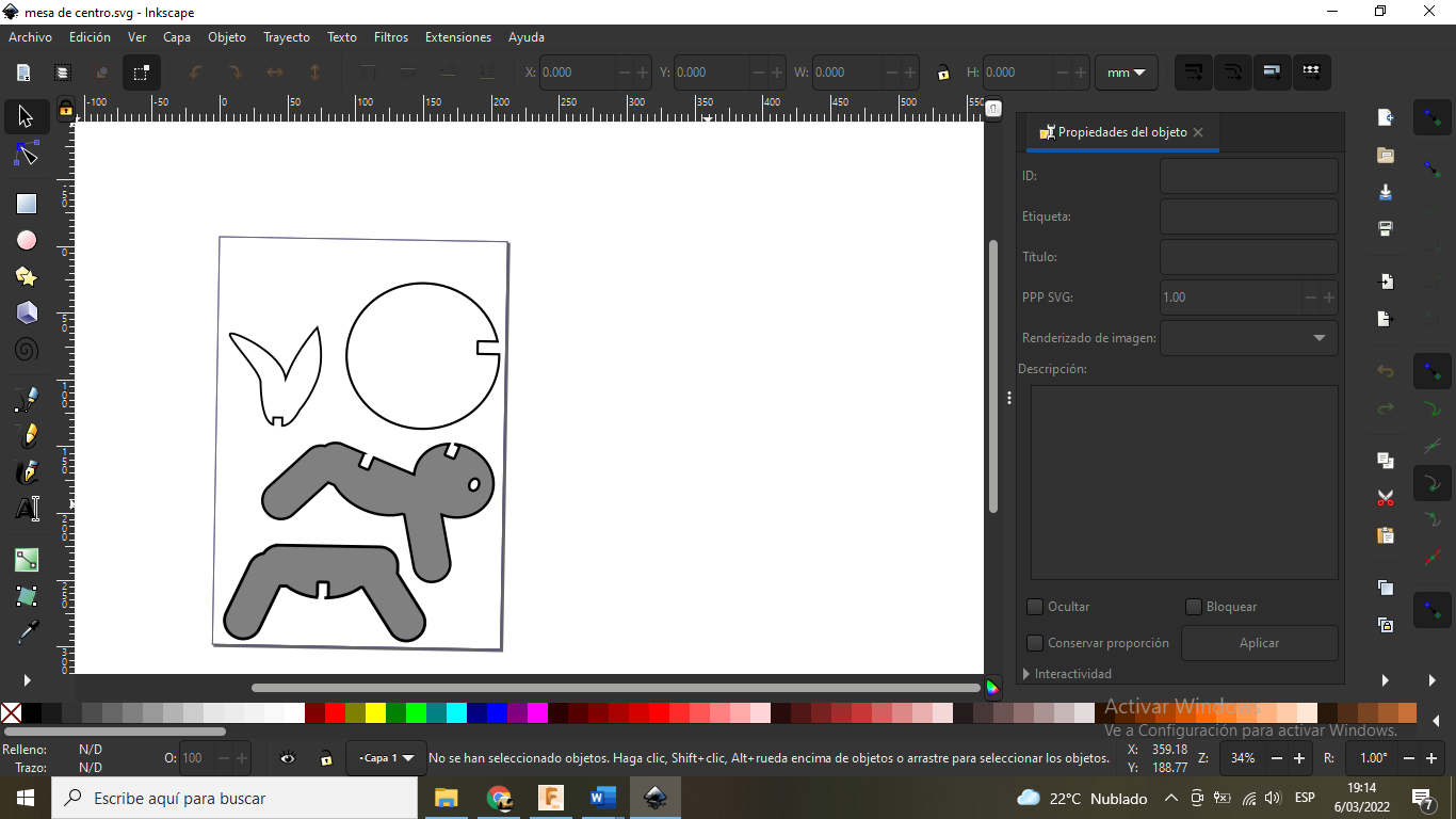
The base is designed to be solid and stable, ensuring safety for its use as a didactic furniture piece.
Download files
-
some files to download from my work done:
- .
- Cut something on the vinylcutter
Video
Download files
-
some files to download from my work done:
- .
- Cut something on the vinylcutter