Picaron Maker 01
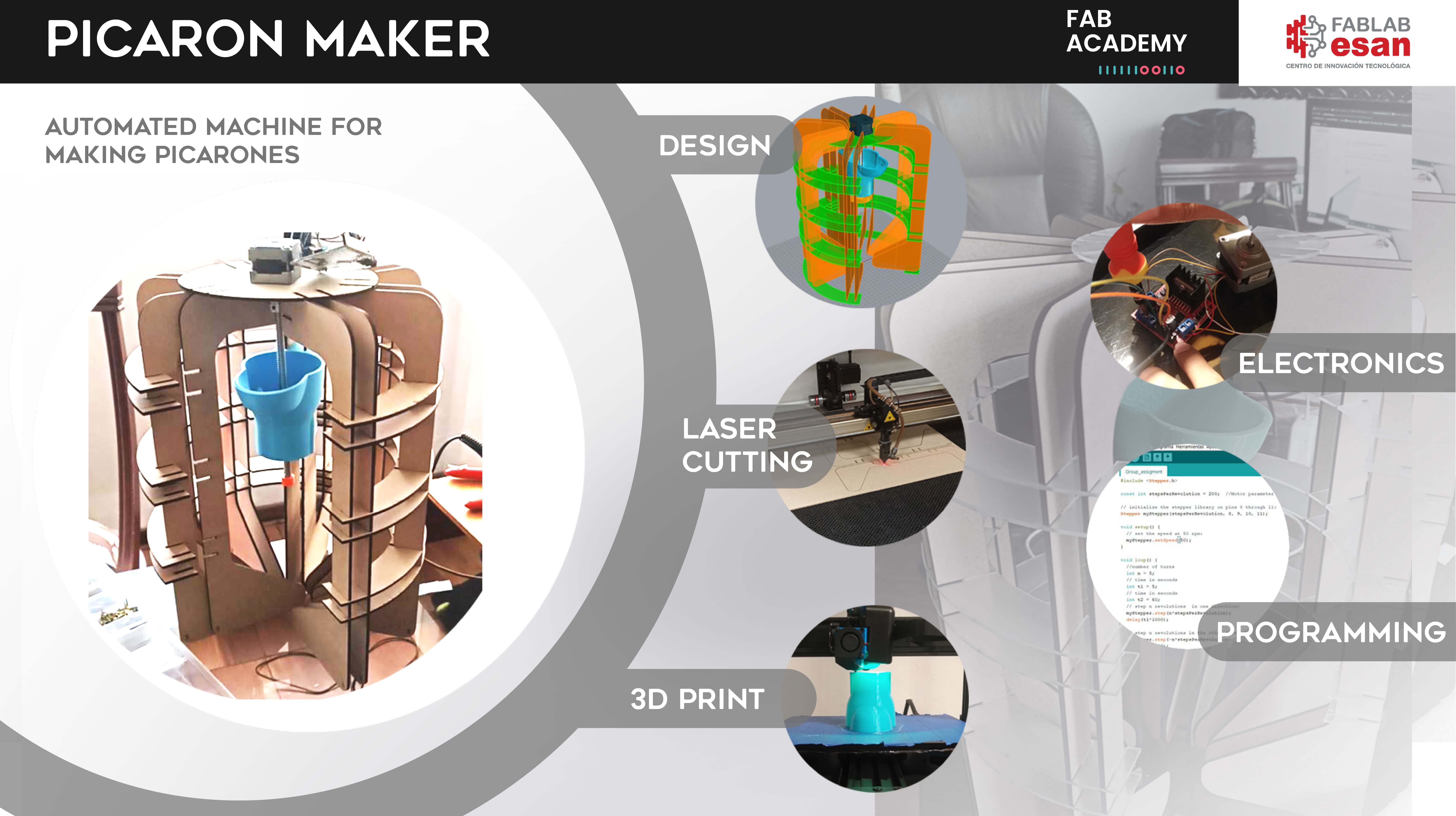
We have a varied gastronomy in Peru, one of the most symbolic desserts is the PICARON and therefore we decided to create a machine that facilitates the process of its production and we created the PICARON MAKER. Join us and see how we built it!
PANEL
VIDEO
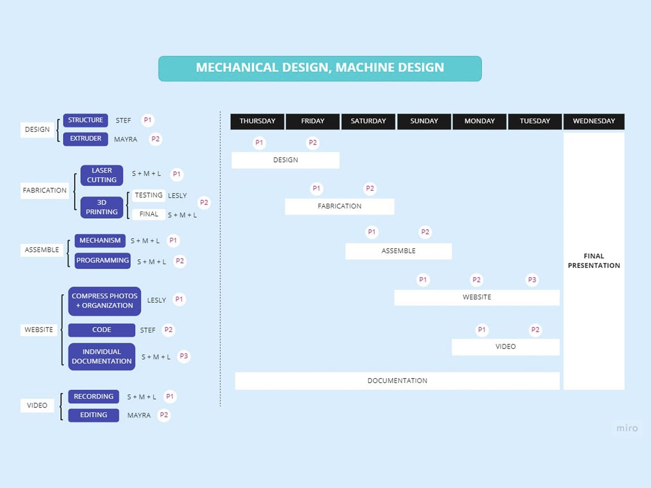
1) SCHEDULE AND WORKFLOW
First, to meet deadlines we draw up a schedule for the development of the project according to the skills of each member and indicating the time available for each activity.
PHASES:
- Design
- Fabrication
- Assemble
- Website
- Video
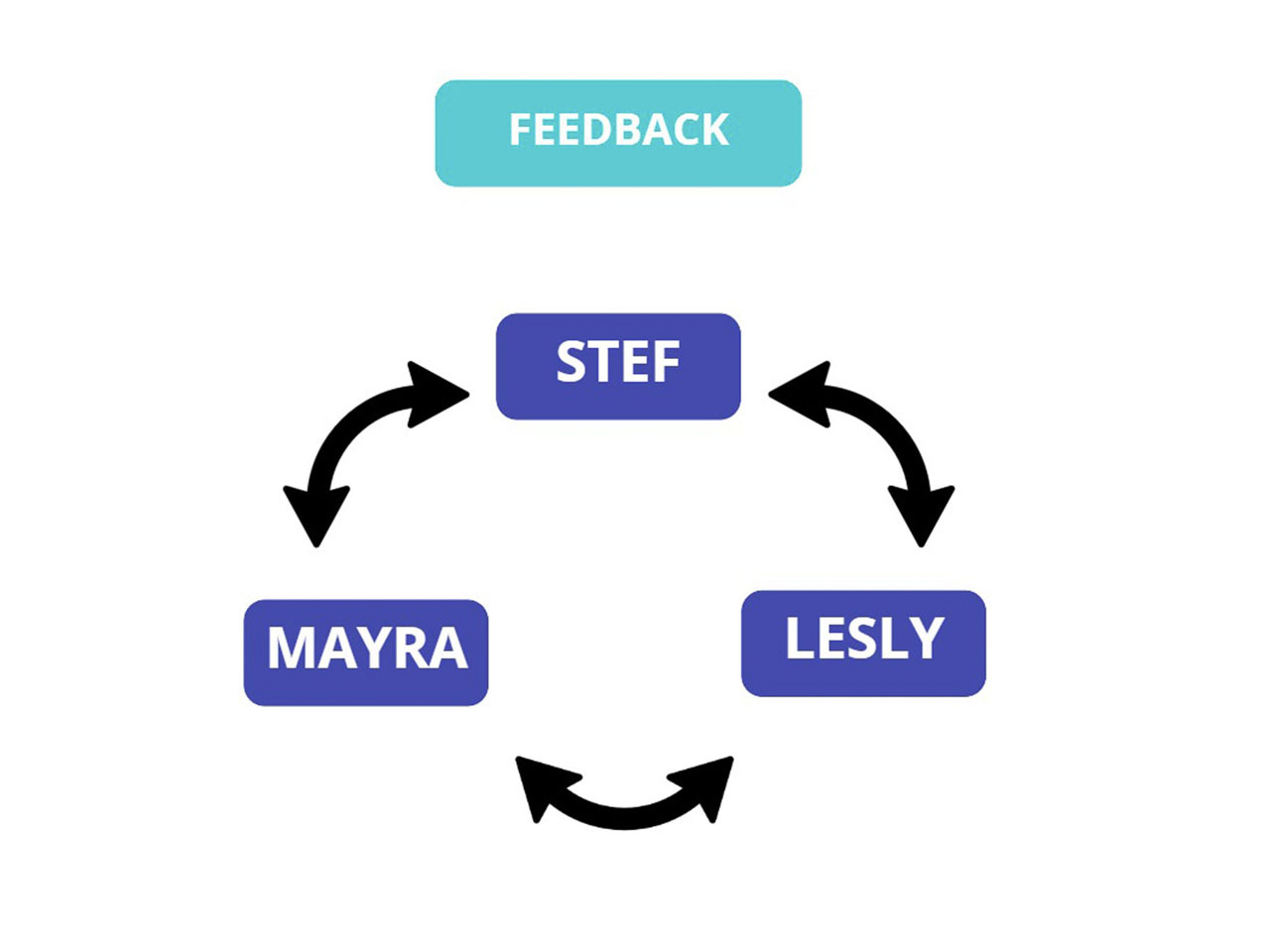
The tasks were distributed, but at each step there was collaboration among the team, giving feeback and advancing their activities in parallel.
When you get a different point of view, you can improve your work and see the mistakes or improvements can be made.
2) WHY PROPOSE THIS PROJECT?
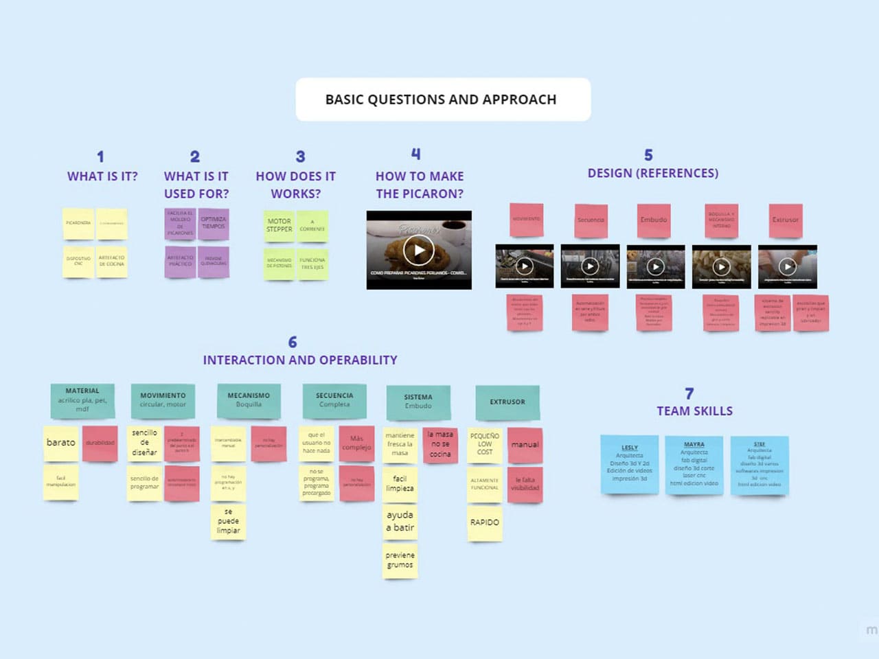
First, prior research was done and the following questions were answered:
What?
What is it for?
How does it work?
Second, we were thinking about something to make and enjoy it, so to define our project we choose something that can be done manually but could be automated, reduce time and improving efficiency.
We proposed this project for:
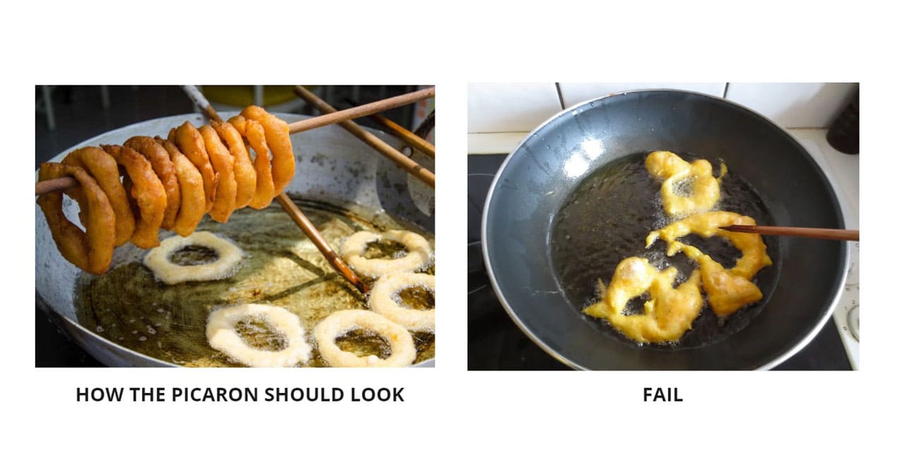
- BEGINNERS: It takes a lot of practice to get the right shape for this dessert, but with our proposal, anyone without previous knowledge can prepare it
- SPEED AND EFFICIENCY: It improves production, especially for businesses that are dedicated to this area.
- ADAPTABILITY: It can be adapted to any place and it is easy to transport.
- CUSTOMIZATION: To be able to create different shapes, fun designs and arouse curiosity in the consumer.
In addition to researching what it is and how it is prepared, we also looked for references of other food machines in order to analyze their mechanism, their interaction and operability, as well as to take into account our skills in order to develop this project.
The following is the scheme of work that was carried out to propose and develop the project.
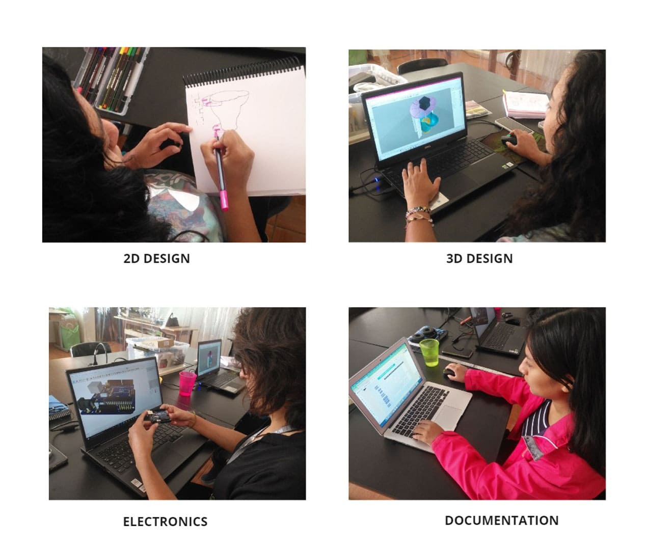
3) EXECUTION
DESIGN
According to the Design Thinking process, each member made a design proposal, indicating how it would work and its advantages as you can see in the following diagram:
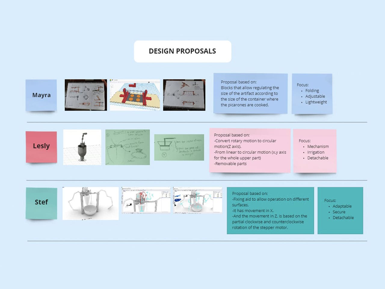
We discussed the ideas and the main design points are:
- Extruder
- Structure
- Electronics
We defined parts of the design and started to move forward in parallel.
Working as a team, despite the pandemic, we were able to get together to do the project and it became a great experience, fun times and also filled with a lot of learning.
Finally, after all the research we came up with the exact components and workflow of the machine:
- EXTRUDER
- STEPPER MOTOR
- MOTOR CONTROLLER MODULE L298N
- ARDUINO UNO
- POWER SUPPLY
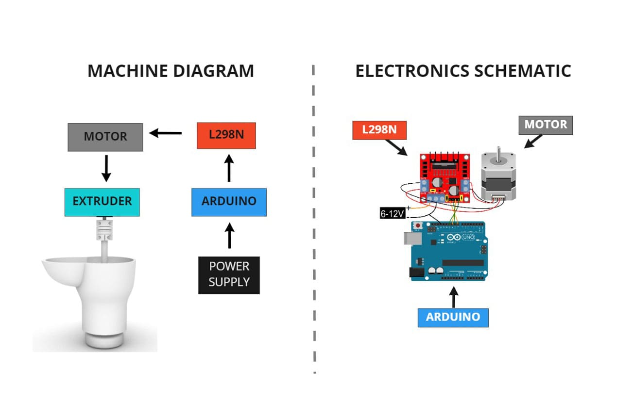
After defining the workflow and components, we continued with the process, improving the design, electronics and documentation.
And here we are, apparently very calm working, but we had many doubts and made tests to see if the pieces fit or works properly 😂.
There are things that sometimes do not turn out the way you imagine them and you have to take into account gravity, knowledge about mechanisms and common sense.
Sometimes there are problems that can be easily solved but sometimes we can't see it, clearing the mind is important.
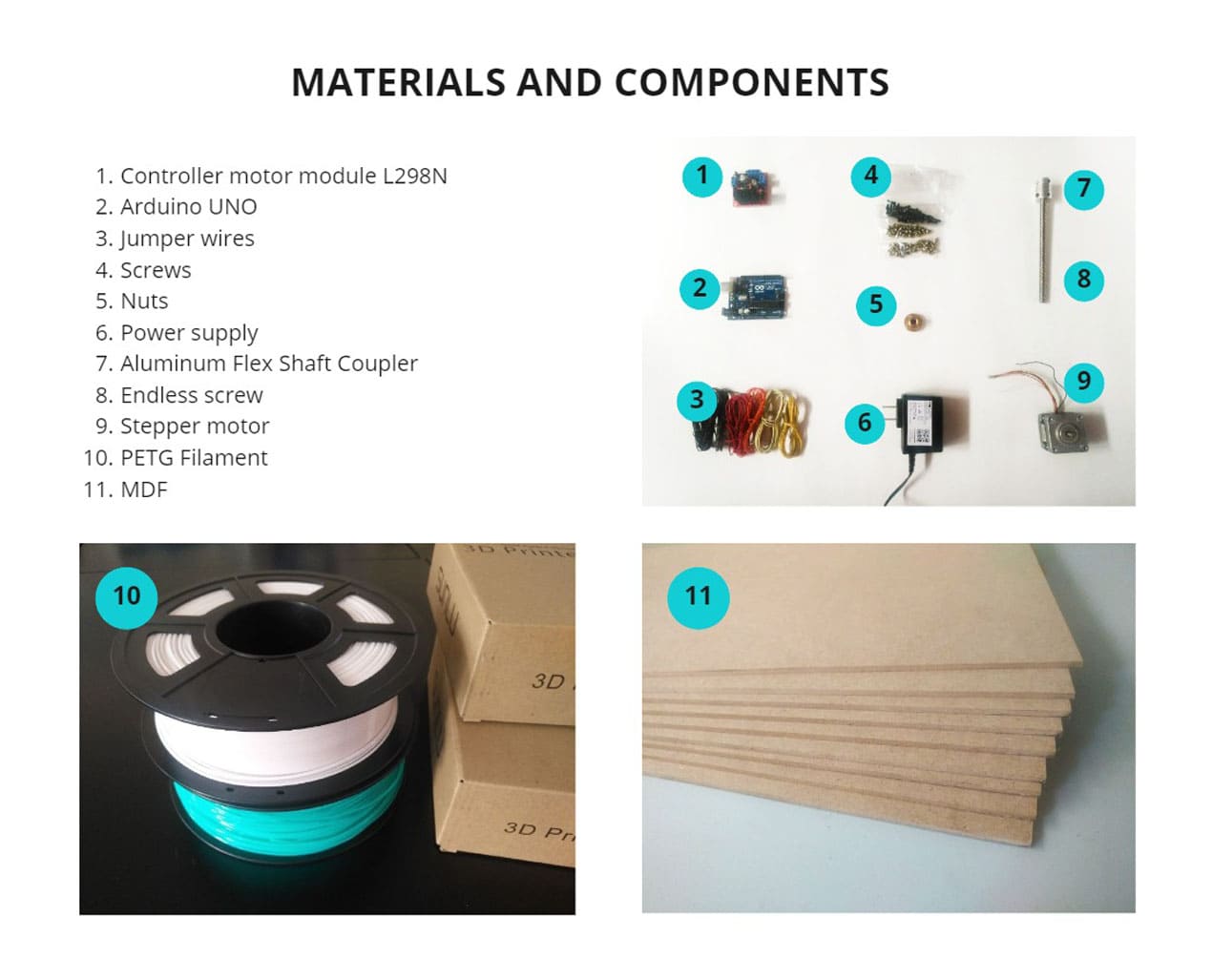
First, we choose the right materials that will suit our entire design :
- Controller motor module L298N
- Arduino UNO
- Jumper wires
- Screws
- Nuts
- Power Supply
- Aluminium Flex Shaft Coupler
- Endless screw
- Stepper motor
- PETG filament
- MDF
For the structure we chose 3mm MDF for better stability.
You can see the materials and components in the next image:
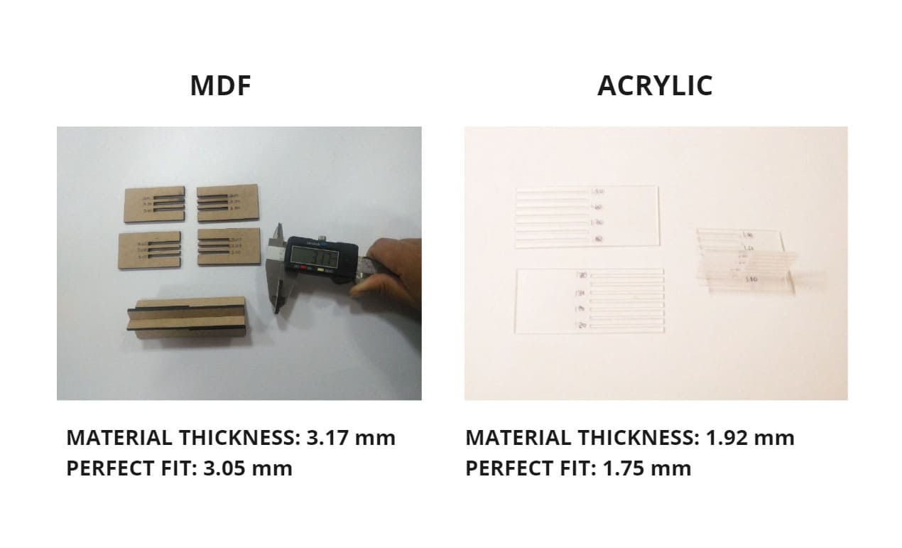
TESTING MATERIALS:
KERF MDF AND ACRYLIC
We have used a different laser cutting machine than the one we used during the week of Computer controlled cutting, therefore, we had to test again in order to have the precise structure fittings and we tested two materials, mdf and acrylic.
As you can see in the following images, the ideal fit we chose for the MDF was 3.05mm, and for the acrylic it was 1.75mm.
FILAMENT
We also test the PETG filament, the minimum recommended configurations to print in the shortest possible time:
- Layer height: 0.28
- Cooling: Off
- Filling: 5%
- Material temperature: 220
- Bed temperature: 80
- Speed: 48
FABRICATION:
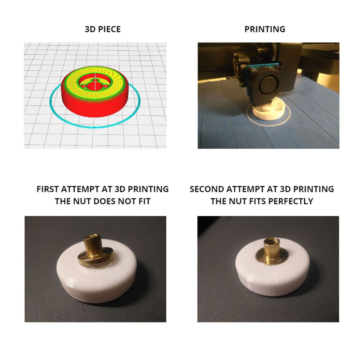
Having the design, we started printing small pieces to see the fit and testing nuts, in the process a lot of mistakes happened....😂😂😂😂😂
First, I opened the 3d file in Ultimaker Cura software, set the following parameters:
- Layer height: 0.28
- Cooling: Off
- Filling: 5%
- Material temperature: 220
- Bed temperature: 80
- Speed: 48
You can see more details in the folling images:
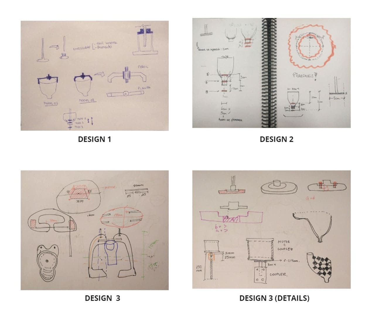
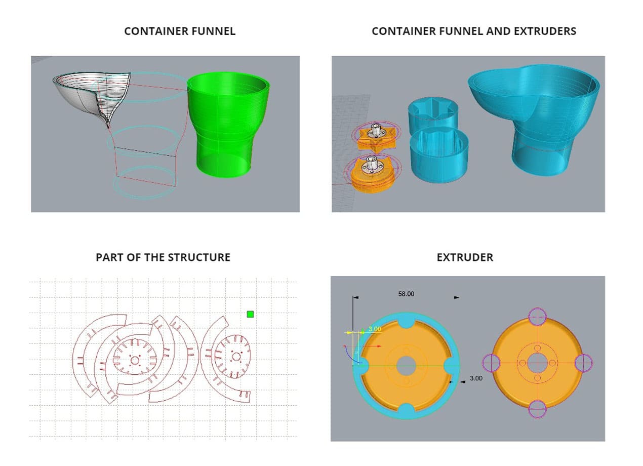
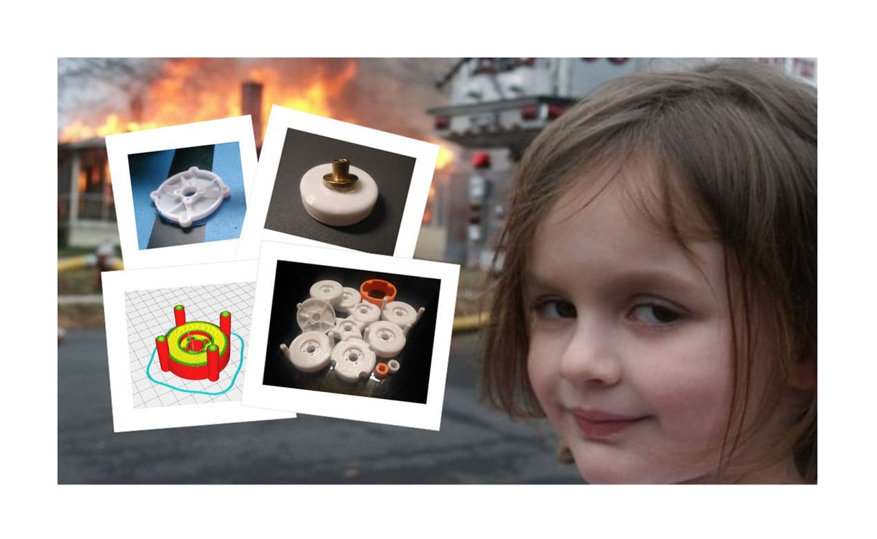
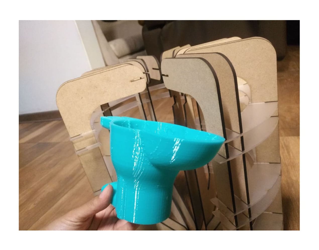
In the next images, you can see the design of each piece of the project. We had several changes before we got to the final parts. From rethinking the main shape of the funnel, the extruder and the structure.
Some parts worked and others were totally discarded.
Join me in this roller roulette of emotions, tears and laughter were not lacking! 😎😎😎😎😎
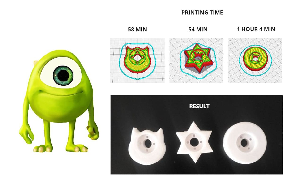
We want to design not only the circle shape like the traditional picaron, we tried to design different shapes like a star and cat, but one of them looks very familiar.
Wazowski, what are you doing there? That's not your family! Accidentally the cat shape looks like Mike Wazowski, it wasn't planned 😅.
One of the things we realized is that if you want to make a different shape, you have to vary the outer and inner shape, i.e. the shape of the funnel and the donut.
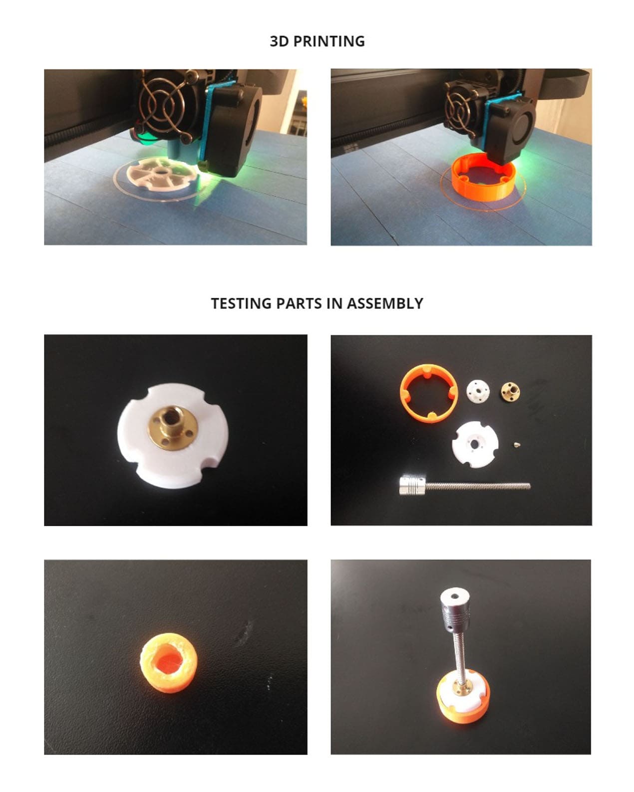
GRAVITY SAID NO!
When everything seemed to be fine, we forgot that the piece could fall without something to stop it...
But a small part would solve our design and internal rails become very important. In this way, no part falls into the vacuum by gravity.
We made several attempts as you can see in the following pictures, but only two rails were necessary to make the mechanism work.
TRY AGAIN!
At this point we didn't know whether to stop and cry for all the hours of 3d printing, so we just smiled and kept going.
After so many mistakes, we finally know what changes are needed to be able to continue manufacturing.
Let's set this thing on fire!
READY TO PRINT AND CUT!
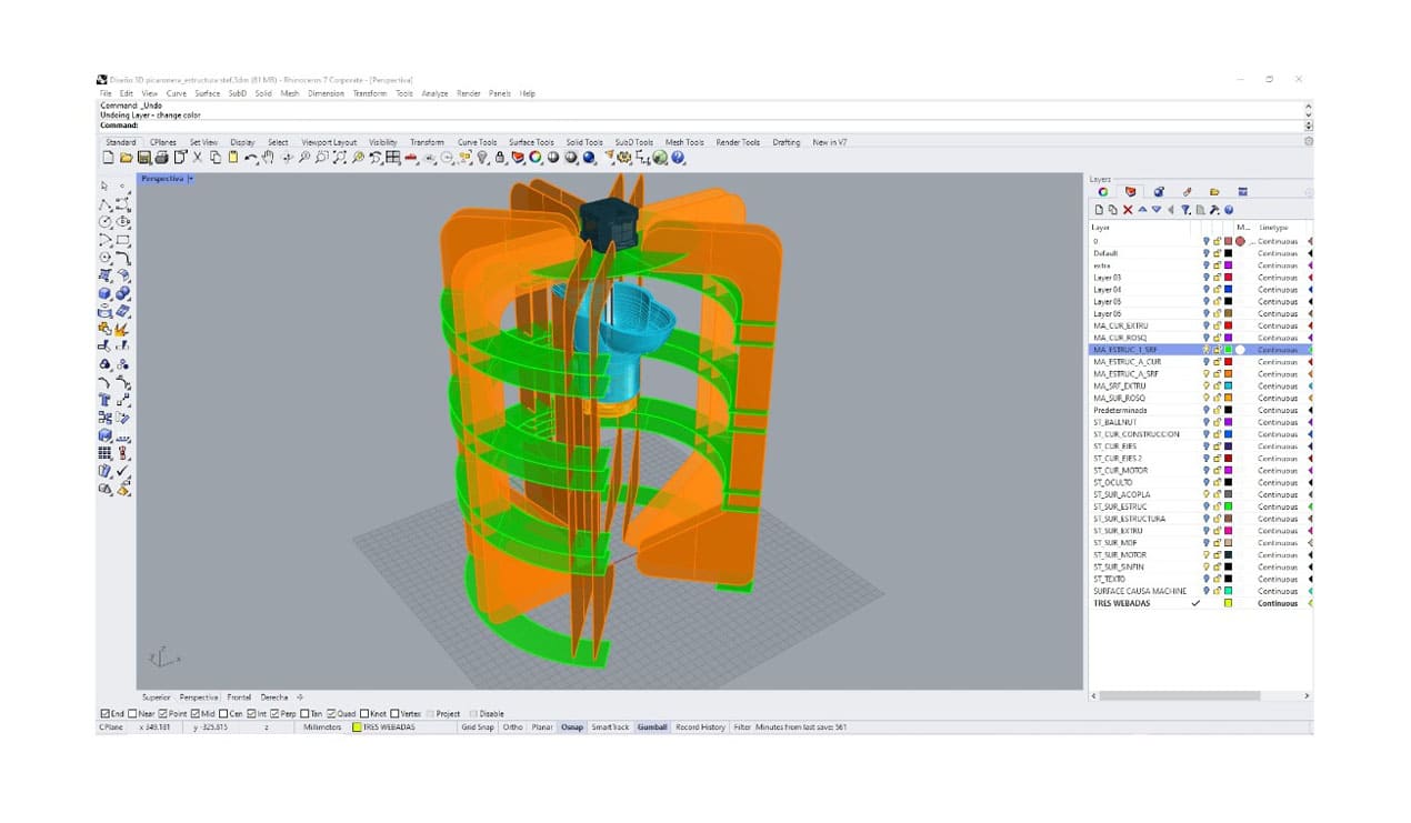
The design took a long time because we went back and changed measurements when something didn't fit. You always have to avoid mistakes in the final pieces, so you can print or cut certain sections and verify that everything fits perfectly, avoiding spending too much material and time. The modeling was done in Rhinoceros.
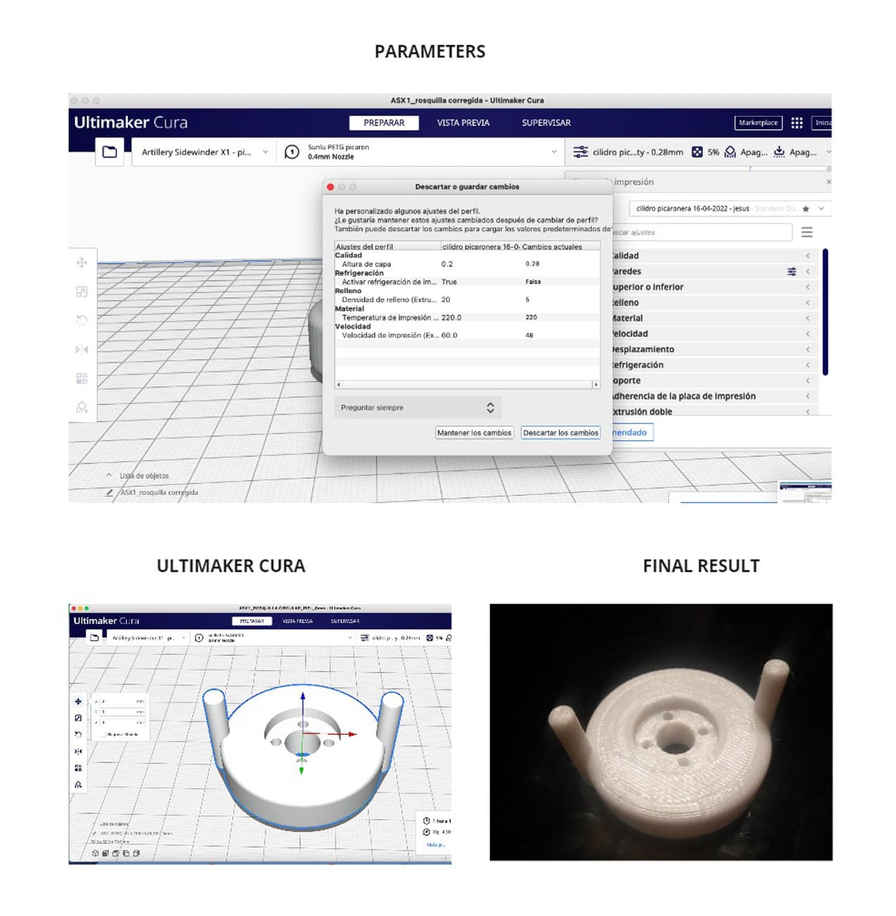
Doughnut shape
This was the first file to print and we use the next setting to print PETG on an Artillery printer, Ultimaker cura was the slicer software that we use to convert it to g.code.
- Layer height: 0.28
- Cooling: Off
- Filling: 5%
- Material temperature: 220
- Bed temperature: 80
- Speed: 48
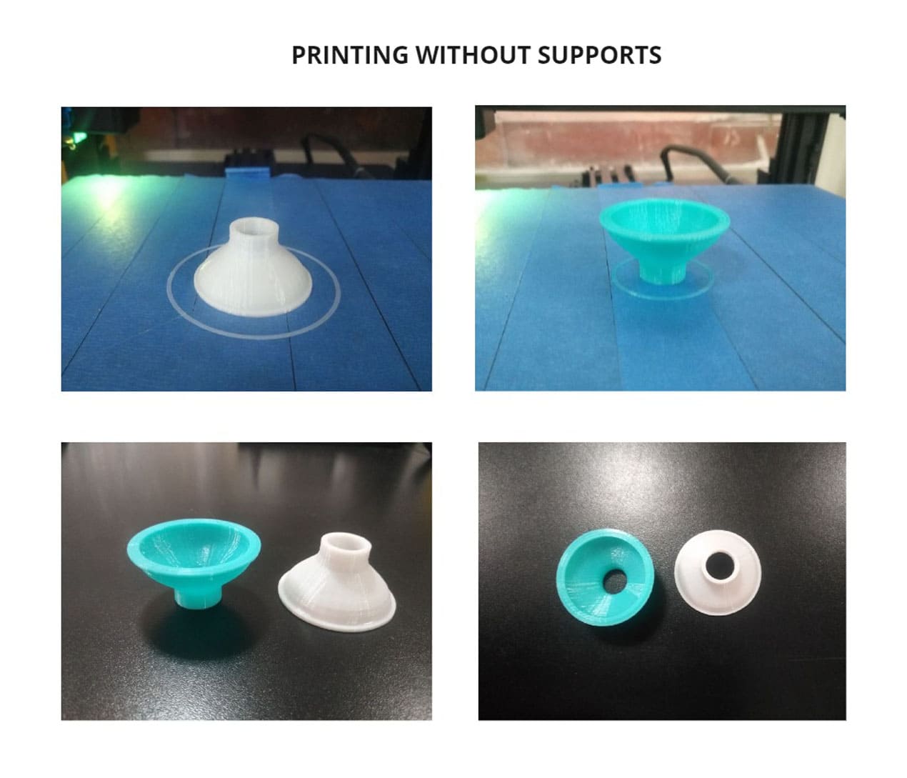
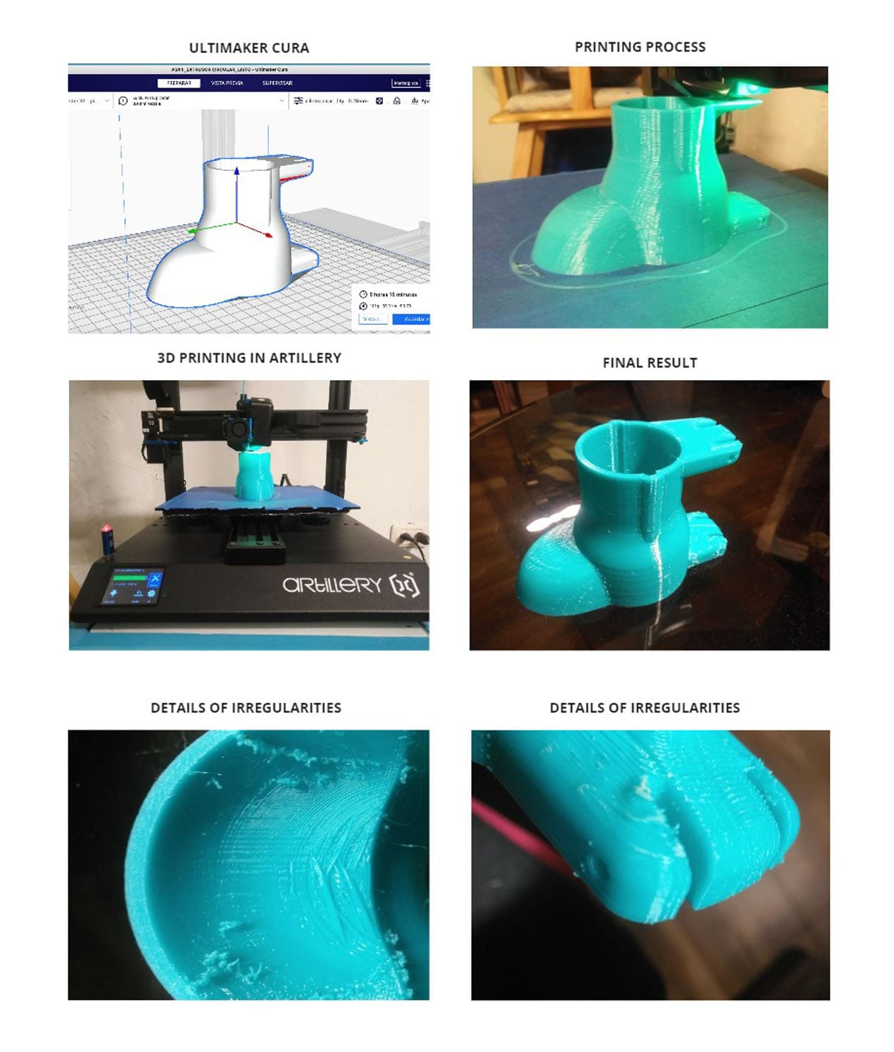
EXTRUDER
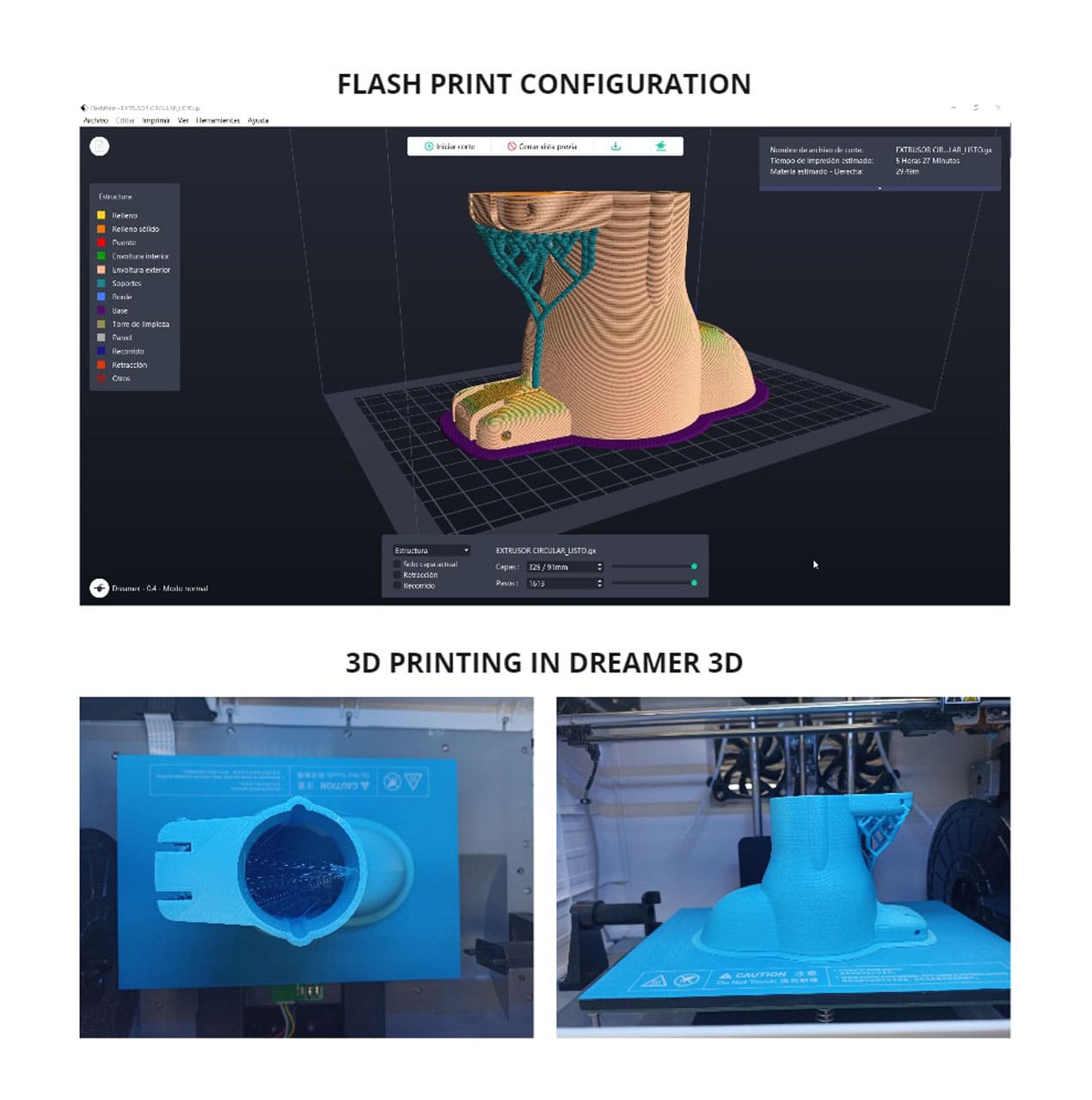
The second file to print was the "EXTRUDER", we call it by this name. The configuration used was the same as in the previous piece.
We changed the parameters to print in less time, but due to these changes, the finish was not the same. The surface was very uneven, and the wind and temperature outside also affected the result.
The quality was not the same and you can check it by looking at the results of the first tests and the actual result, you can see more detail in the following photos:
We made a second parallel print with a DREAMER 3D printer, added supports and the result was different, much more uniform and could be done in less time.
We have used the FLASHPRINT software and the printing time was 5 hours 27 min.
The surface was smoother, dentrite supports were added but were also difficult to remove. The filament used was PLA and is not suitable for food contact.
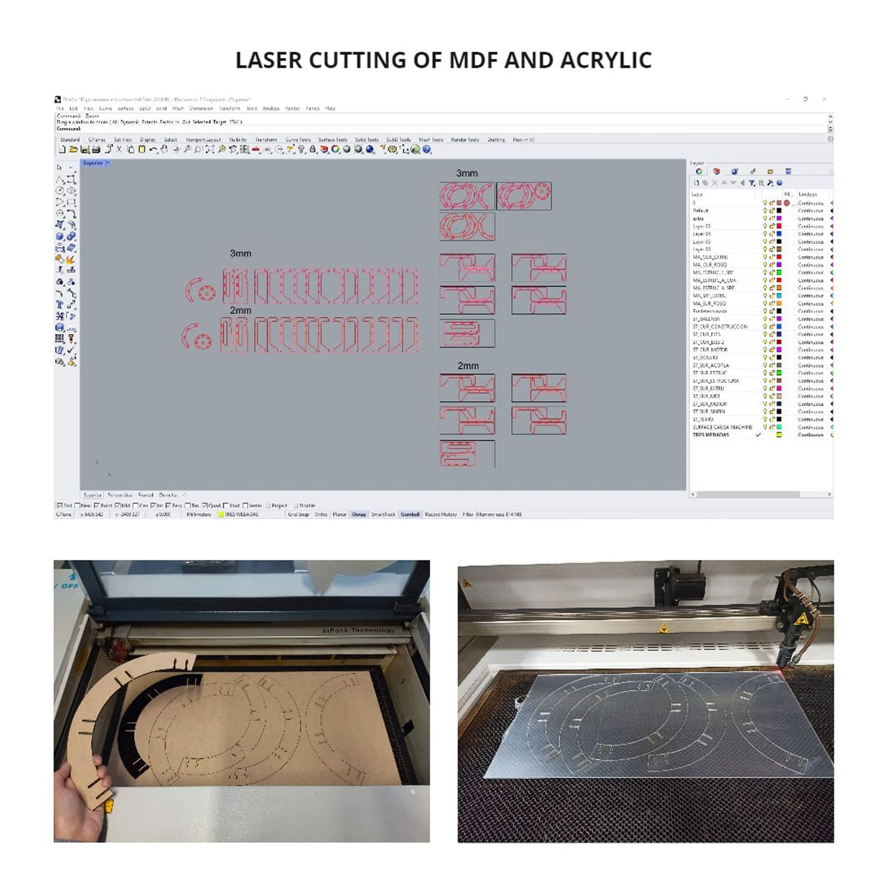
CUTTING
For the cutting of pieces we made two versions, in one we used only 3mm MDF and in the other 2mm acrylic, that way we could have two models of structures and see the difference in balance, strength and aesthetics.
The parameters were well set and the parts were cut correctly without burning.
For the cutting process, the same steps were performed as the laser cutting group assignment to prepare the machine and send the file.
Speed: 15mm/s
Power: 45.0%
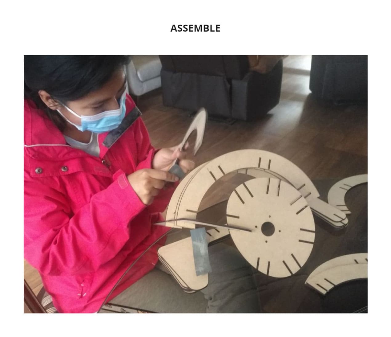
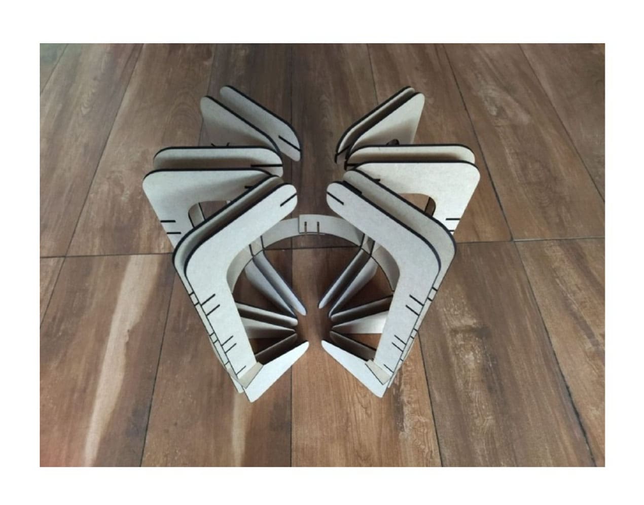
ASSEMBLE
One of the things we noticed during assembly was that the fittings were too tight, it was difficult to assemble all the pieces.
At this point you only have two options, sand the actual pieces or correct the measurements and cut new pieces, we chose the second option, this saved us time. Still there were problems fitting the final piece.
You can see the process below:
PROGRAMMING
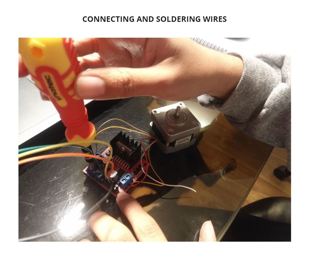
We use the Arduino IDE software to program, place the wires and solder the connections with tin.
Remember that before connecting you must take into account the type of motor and its data sheet. Then we correctly connect the wires to the computer and start programming, we define the type of motor and its speed, in this case a stepper motor, finally the amount of time it will rotate and the sequences it will follow.
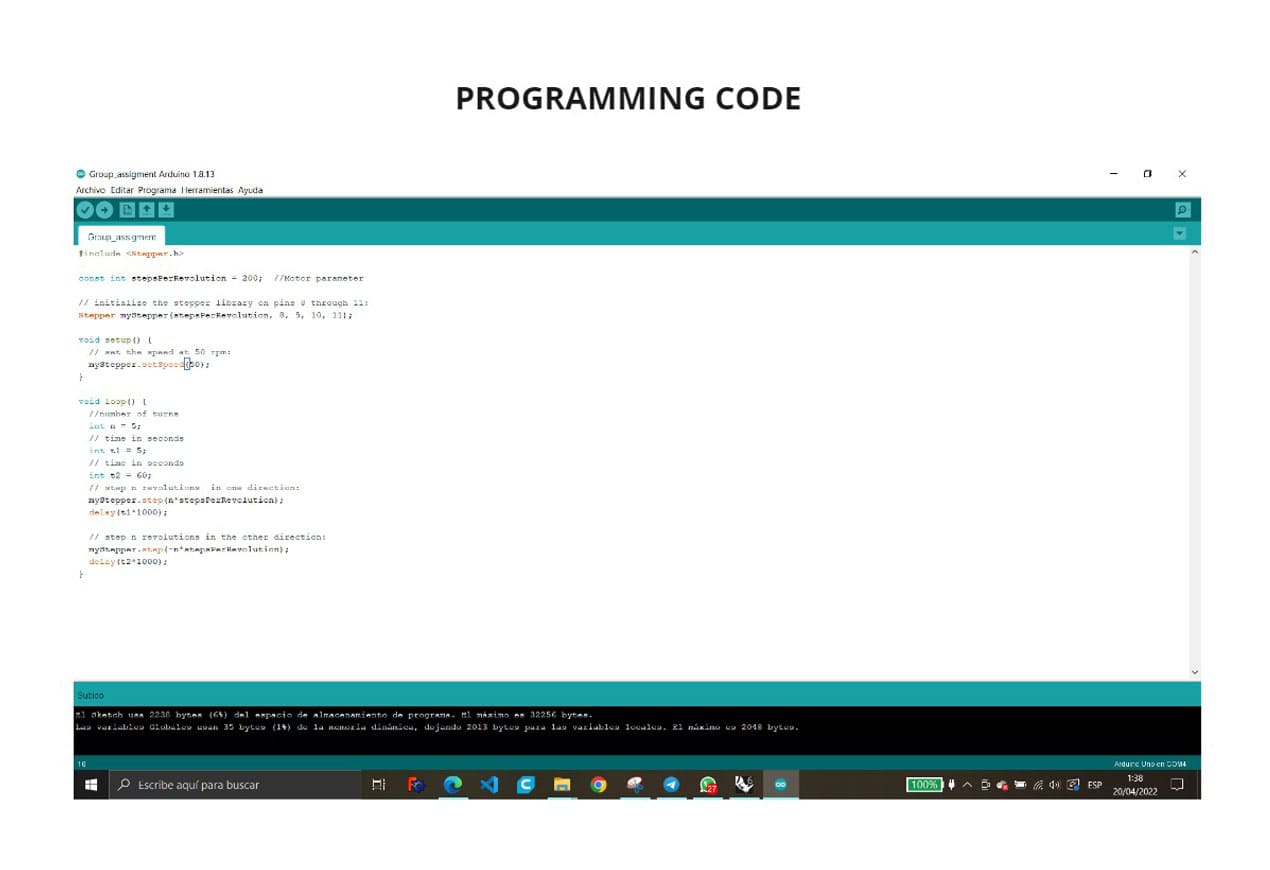
You can see the code below:
#include


                const int stepsPerRevolution = 200; //Motor parameter


                //initialize the stepper library on pins 8 through 11:

                Stepper myStepper(stepsPerRevolution, 8, 9 , 10, 11);


                void setup() {

                //set the speed at 50 rpm:

                myStepper.setSpeed(50);


                }


                void loop() {

                //number of turns

                int n = 5;

                //time in seconds

                int t1 = 5;

                //time in seconds

                int t2 = 60;

                // step n revolutions in the other direction

                myStepper.step(-n*stepsPerRevolution);

                delay(t1*1000);


                //step n revolutions in the other direction:

                myStepper.step(-n*stepsPerRevolution);

                delay(t2*1000);

                }
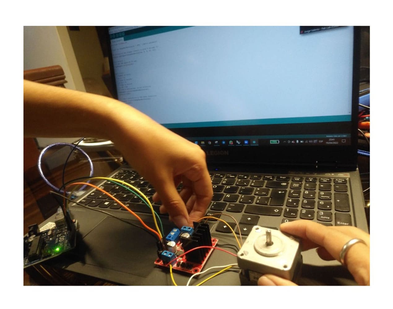
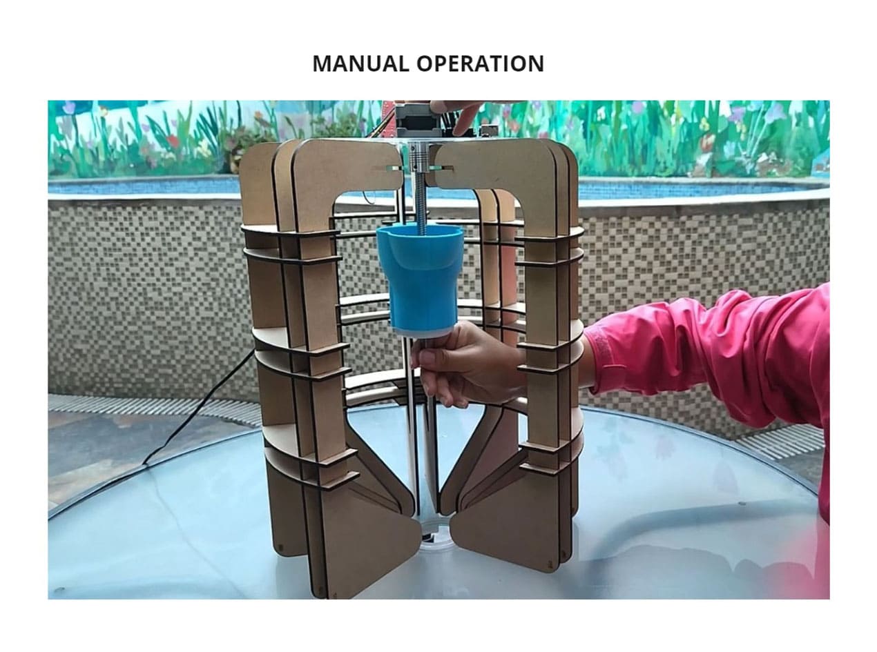
TESTING MACHINE
Finally we tested it manually and the mechanism worked, after programming it we tested it by connecting it to the power supply and it also worked.
With this machine you will get traditional picarones very easily.
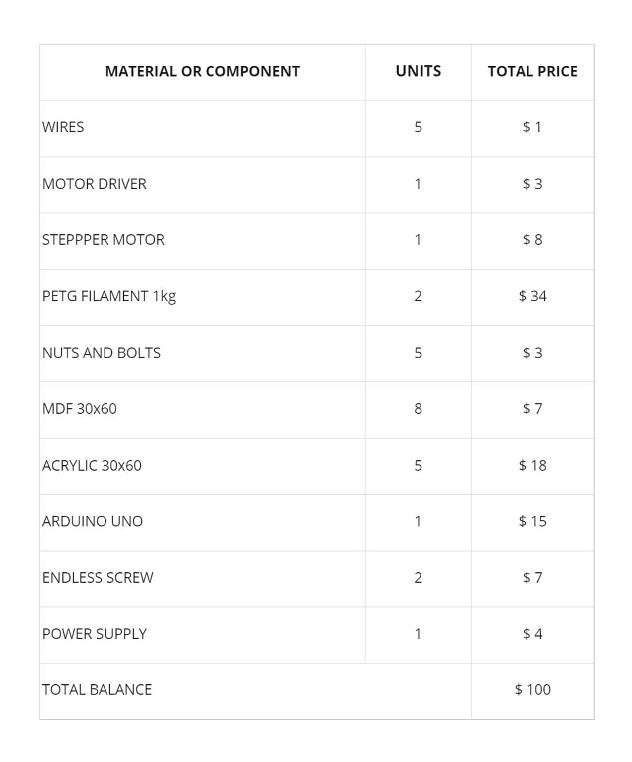
BOM (BILL OF MATERIALS)
4) FUTURE OF THE MACHINE
Improvements can be made to the prototype to help customize designs by changing 2 parts of the machine and make this possible faster and at lower cost, giving the added value of customization.
Due to the speed and efficiency of production it can be incorporated for business, improving the response to the consumer public by the reduced waiting time.
It can be adapted to other types of dough, not just picarones, and with modifications, improvements could be made, such as adding a little oil to the edges to make it easier for the dough to come out.
There are many possibilities to make this a commercial product. Prototyping is one of the great tools that helps us to create, improve and realize projects, it has been very interesting to participate in this experience.
5) CONCLUSIONS
There are many improvements to be made, this experience helped us to see the workflow and deal with setbacks that may arise.
Automation can greatly improve the efficiency of a service or product, but in addition to that, adding value such as personalization can be even better, the combination of these two ideas could cover many needs in businesses, especially emerging ones.
The design can be further simplified, improving aesthetics and performance, finding that balance is essential. In every project you go through a learning process and this was no exception, I learned more elements that I can work with again in the future.
6) FILES
Students
Continuing Students
New Students
Instructors