Kinetic Window
The members of the group are architects. Our interest arises in some architectural element. In this case, a kinetic window that can create different textures through the movement of some of its parts to allow the passage of light in order to create visual sensations.
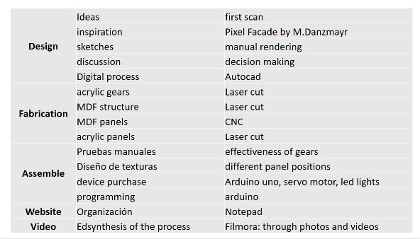
SCHEDULE AND WORKFLOW
First, to meet the deadlines, we prepare a schedule for the development of the project according to the skills of each member and indicating the time available for each activity.
STAGES:
- Design
- Manufacturing
- To assemble
- Website
- Video
DESIGN
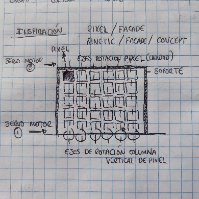
INSPIRATION
For this work he started by reviewing the Pixel Facade designed by Matthias Danzmayr, which is documented on his website. The concept of the façade was to have three states of opening. Fully open, fully closed and partially open. Another desired feature was the ability to rotate all partially open panels at the same time to create a wave animation on the building.
SKETCHES
Based on inspiration as reference work. The following drawing was made to better express our design intentions. The main idea is to create panels that can rotate to create various visual sensation scenarios. For this, the movement of these panels through a servo motor is proposed. These panels must have properties of transparency and solidity to explore various textures. A wooden support for the window was raised
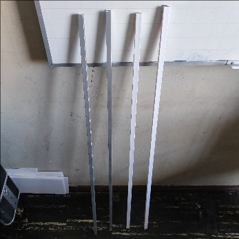
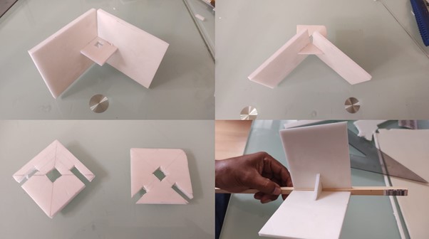
DISCUSSION
Small prototypes were made to explore the movement and fabrics of the panels. We explore various vertical structures for the movement of the panels. We study wood, plastic and aluminum. This allowed us to make decisions. We decided to use wood for the vertical axes as it was light in weight, had good stiffness and was easy to work with.
DIGITAL PROCESS
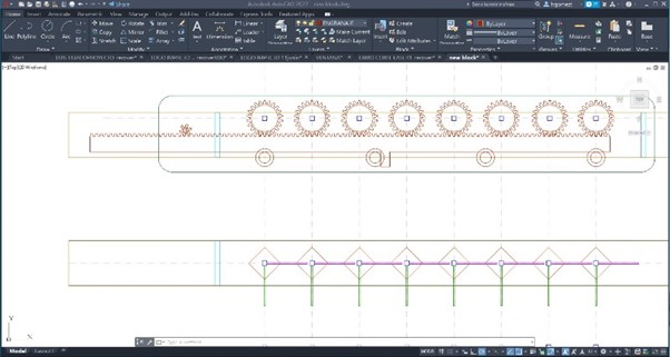
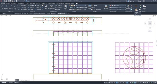
Gear design was the trickiest part. It helped us a lot to have the example of Pixel Facade.
Each of the pieces was digitally designed in autocad:
- The gears. It helped us a lot to have the example of Pixel Facade.
- MDF frame to support the entire window.
- MDF base to hide the mechanical and electronic system
- Square panels
- Vertical structure and panel connection piece
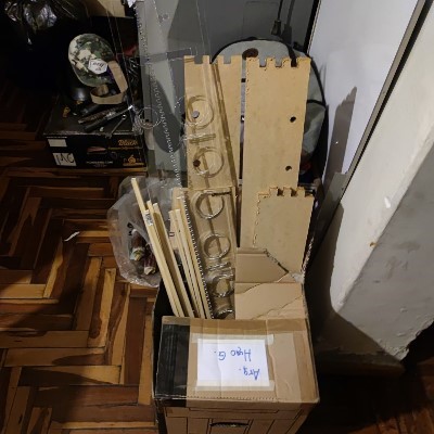
FABRICATION
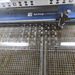
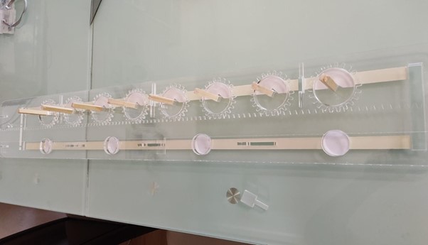
For the manufacture of gears and acrylic joint parts, it was exported from autocad to PDF. The file was opened in CorelDraw and run on the laser cutting machine. The internal parameters of 4mm acrylic cutting were imported. Several models were printed until the vertical wooden structure fits into the holes of the gears.
For the manufacture of acrylic panels, it was exported from autocad to PDF. The file was opened in CorelDraw and run on the laser cutting machine. 2mm acrylic cutting internal parameters were imported.
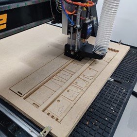
For the manufacture of MDF panels, it was exported from autocad to PDF. The file was opened in CorelDraw and run on the laser cutting machine. Internal 2mm wood cutting parameters were imported.
For the manufacture of the base and the frame of the MDF window it was exported from autocad to PDF. The file was opened in Inkscape and saved in .SVG format. With the Online JSCUT application, the cutting code for the CNC mill machine was created.
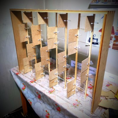
ASSEMBLE
Some manual tests were made for the correct operation of the mechanical gear system.
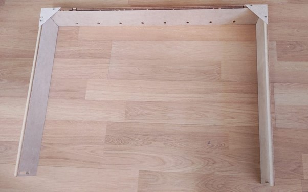
The window frame was made of 15mm MDF.
Joined the gear system with the window frame
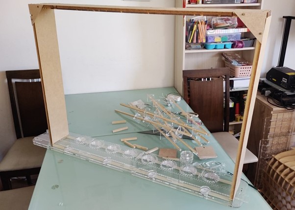
The fabric of the panels was explored creating different textures through movement
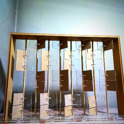
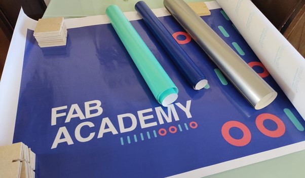
It was decided to give it more visual complexity with a printed image. With the help of the cutting plotter, we cut the self-adhesive vinyl to cover the pixels.
A servo motor was purchased to move the gear system. This is where we had the most problems. On some occasions the pieces got stuck and did not rotate. We had to assemble the whole system several times in such a way that the panels were fixed and did not collide with each other in the turn. It was hard work and time invested.
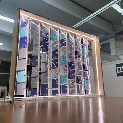
We opted to place LED lights to improve visual sensations.
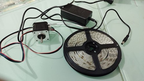
An arduino 1 board was also bought to program the motor and the lights.
PROGRAMMING
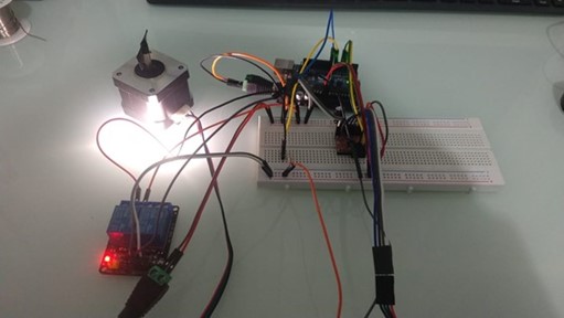
We use the Arduino IDE software to program. We correctly connect the cables to the computer and start programming, we define the type of motor and its speed, in this case a stepper motor, finally the time it will rotate and the sequences it will follow.
Finally we tested it manually and the mechanism worked, after programming we tested it by connecting it to the power supply and it also worked.
You can see the code below:
              //initialize the stepper library on pins 8 through 11:

              Stepper myStepper(stepsPerRevolution, 8, 9 , 10, 11);


              void setup() {

              //set the speed at 50 rpm:

              myStepper.setSpeed(50);

              }


              void loop() {

              //number of turns

              int n = 5;

              //time in seconds

              int t1 = 5;

              //time in seconds

              int t2 = 60;

              // step n revolutions in the other direction

              myStepper.step(-n*stepsPerRevolution);

              delay(t1*1000);


              //step n revolutions in the other direction:

              myStepper.step(-n*stepsPerRevolution);

              delay(t2*1000);

              }
The end result was as follows: A completely transparent face is presented. With another twist you can see the Fab Academy logo. In another you can see different colors of vinyl-coated MDF prisons. In addition, the light frames the window.
Materials list:
- Wires
- Acrylic
- MDF
- Servo Motor
- ARDUINO UNO
- led lights
- Vinyl
- wooden slats
FUTURE OF THE MACHINE
It is the first machine we make and in that sense it has changed our way of perceiving architectural elements. In this experience of making the kinetic window, we observe a great potential to continue exploring the spatial qualities that the envelope can give us in buildings. The window in particular is the contact between the environment and the interior of the room.
You can still scan the axes of rotation in multiple directions and not just one axis of rotation. More sensory elements can be inserted to create different atmospheres through textures, colors, movement, etc.
There are many possibilities to make this a commercial product. Prototyping is one of the great tools that helps us create, improve and carry out projects. It has been very interesting to participate in this experience.
CONCLUSIONS
As architects we are used to designing static architectural elements. It was a challenge for us to think of movement through gears and axis of rotation. The work will help us in future jobs since we learned mechanical and automation processes.
FILES
Students
Continuing Students
New Students
Instructors