Computer-Controlled Machining
Assignment requirements:
Group Assignment
- Test runout, alignment, speeds, feeds, and toolpaths for your machine.
- Document your work (in a group or individually).
Individual Assignment
- Make (design+mill+assemble) something big.
- Extra credit: don't use fasteners or glue.
- Extra credit: include curved surfaces.
- Post processing → sanding, painting.
Learning outcomes:
- Demonstrate 2D design development for CNC production.
- Describe workflows for CNC production.
Assessment criteria
- Linked to the group assignment page.
- Documented how you designed your object (something big).
- Documented how you made your CAM-toolpath.
- Documented how you made something BIG (setting up the machine, using fixings, testing joints, adjusting feeds and speeds, depth of cut etc.).
- Described problems and how you fixed them.
- Included your design files and 'hero shot' photos of final object.
Group Assignment
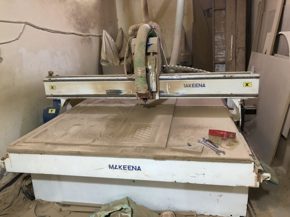
In this week we want to design cool designs in meter scale, we had a small CNC router machine in our lab and had access to a big machine in another workshop.
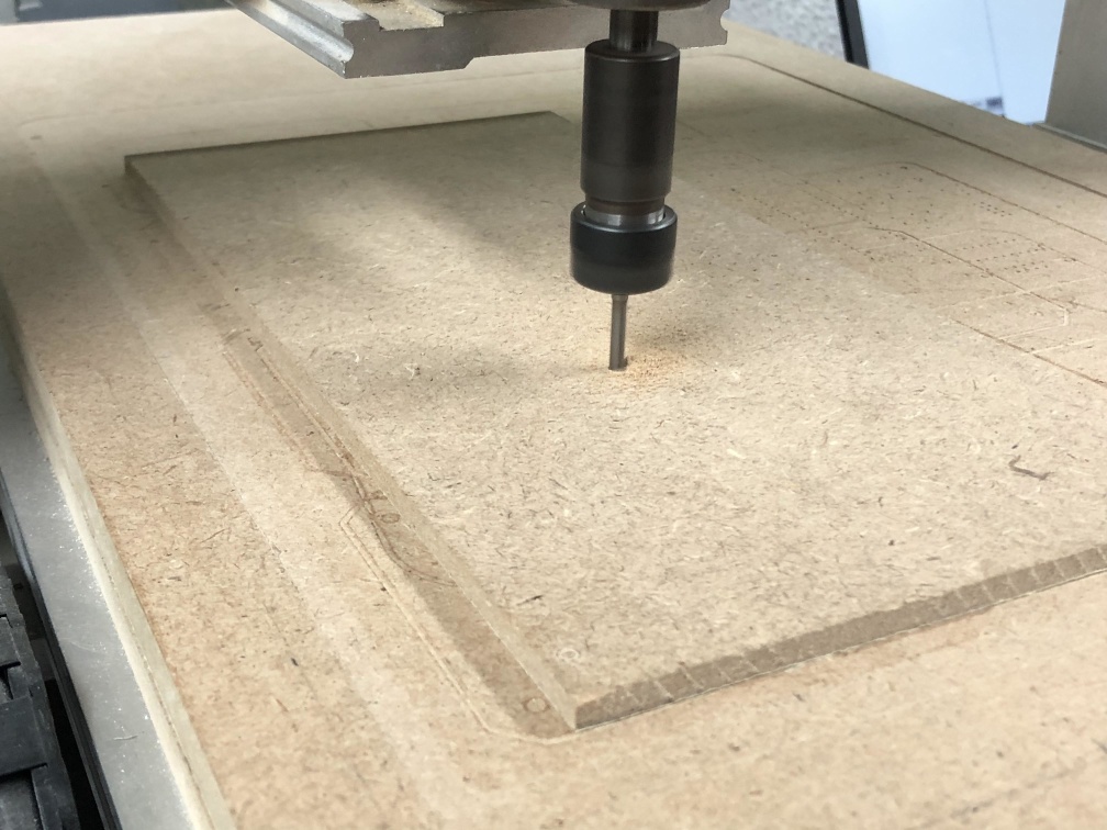
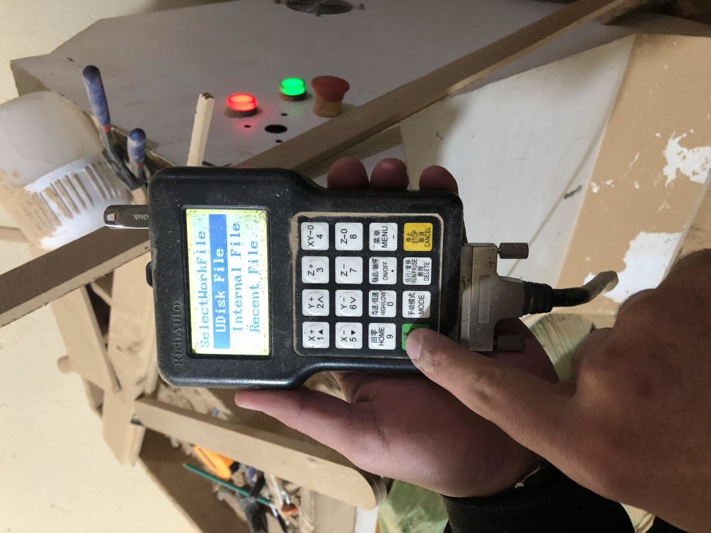
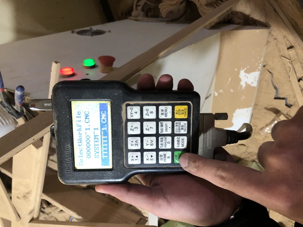
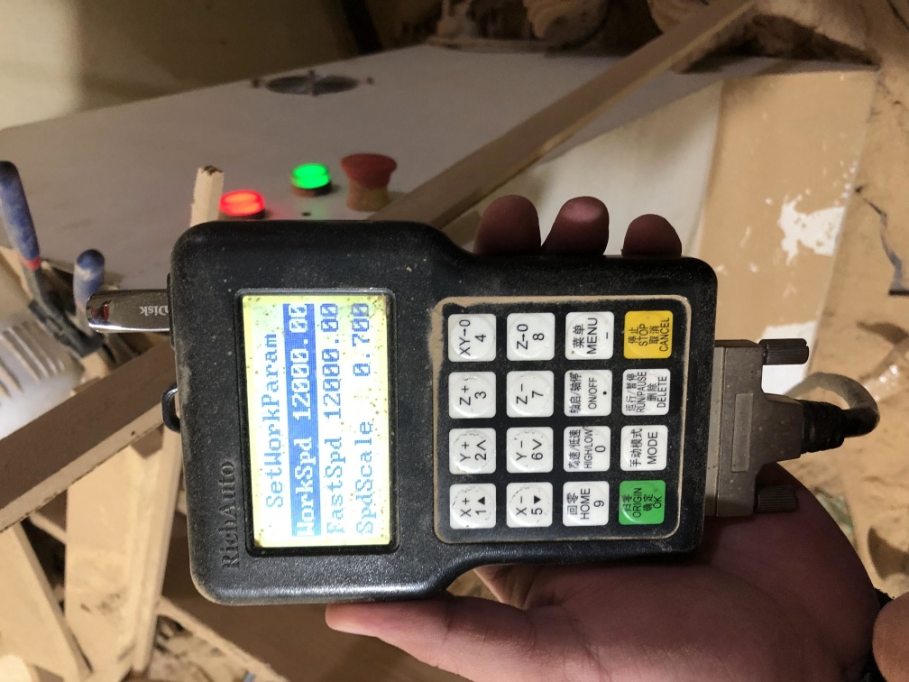
So we started our week by testing a small parts using our machine.
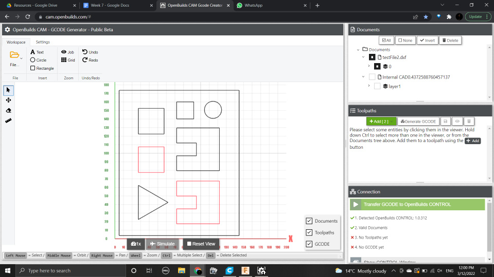
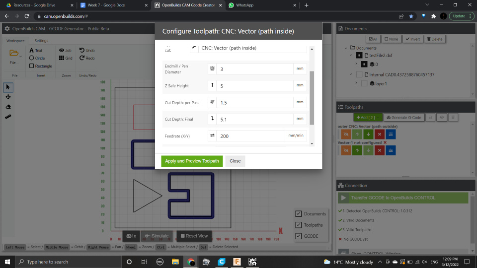
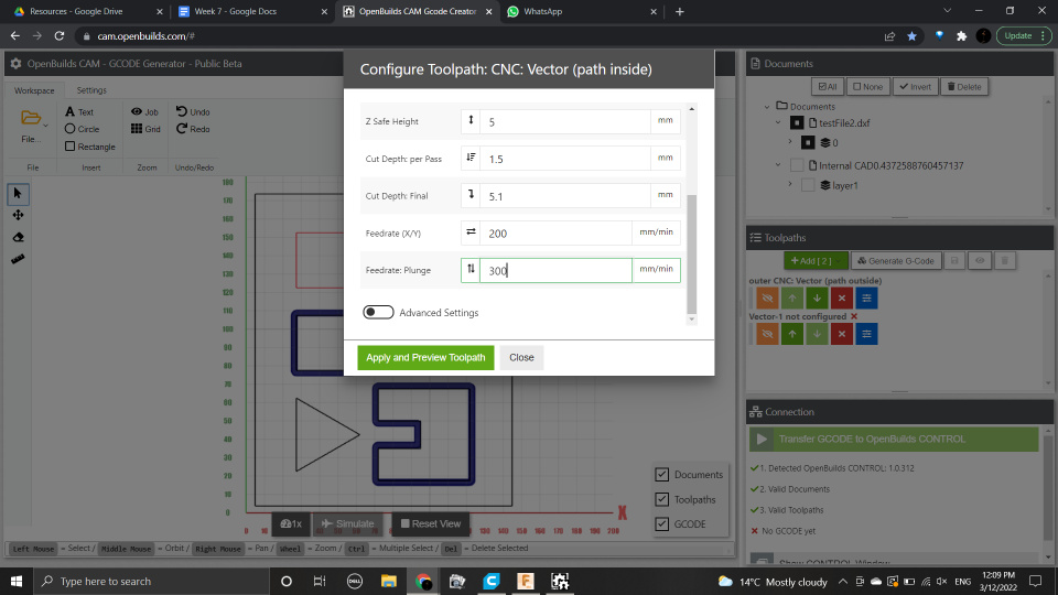
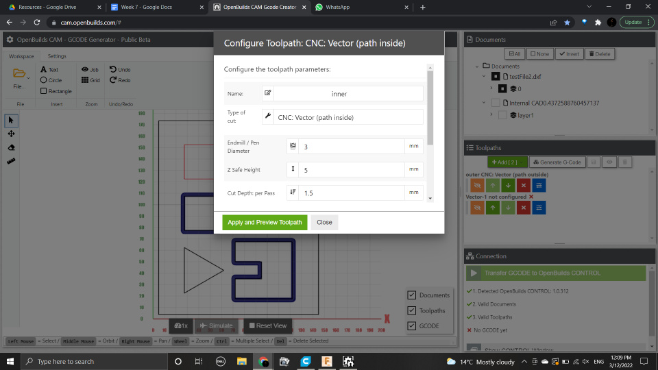
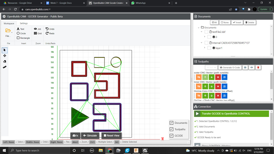
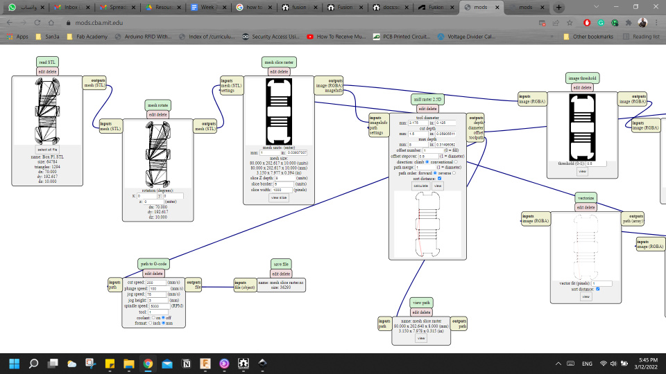
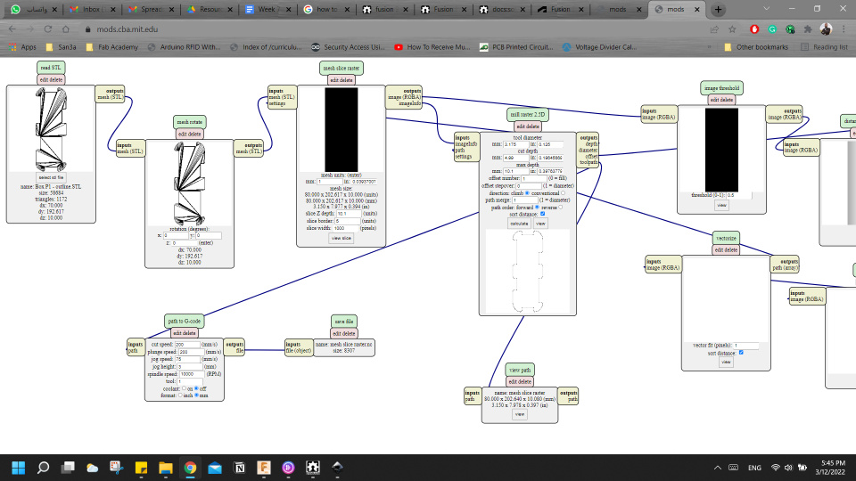
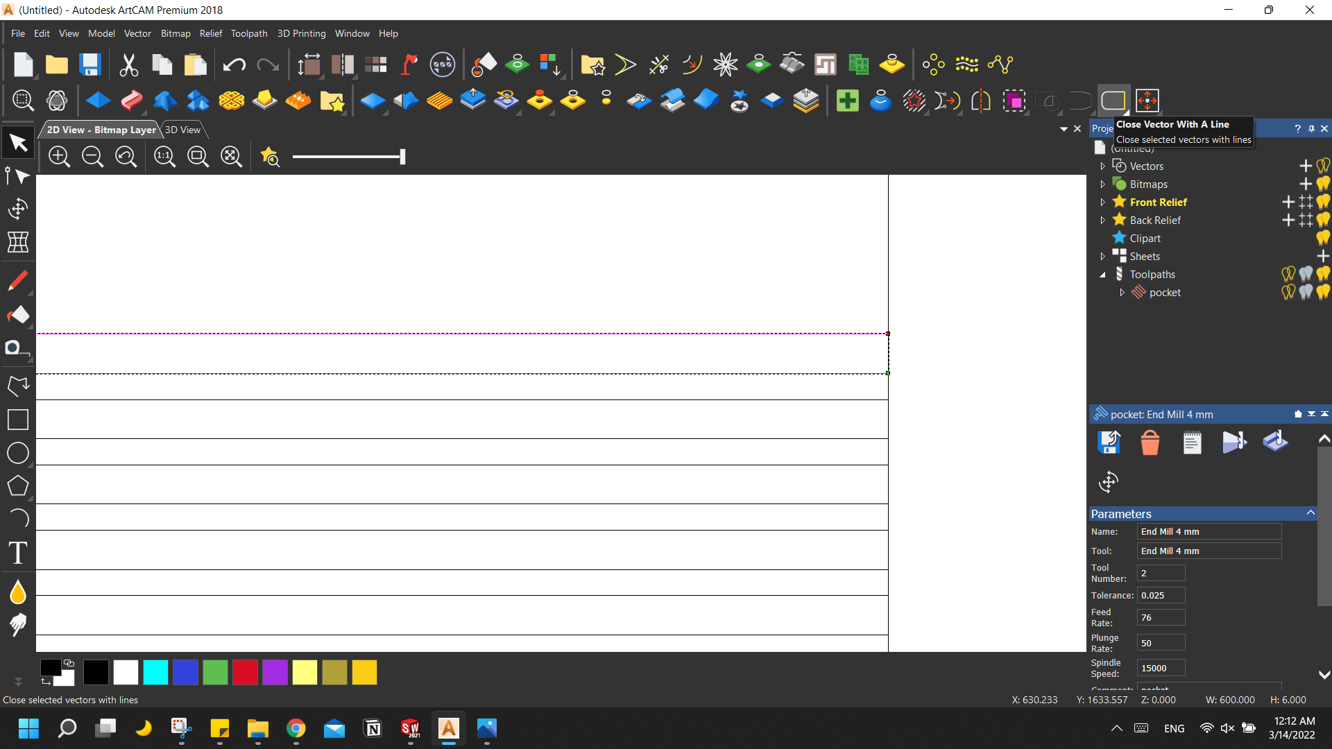
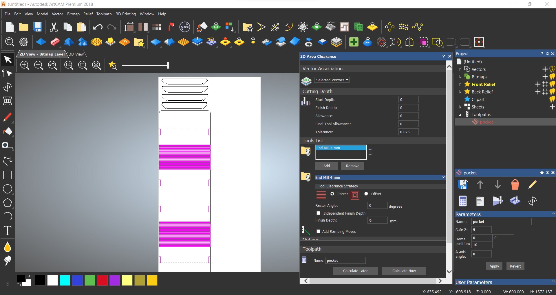
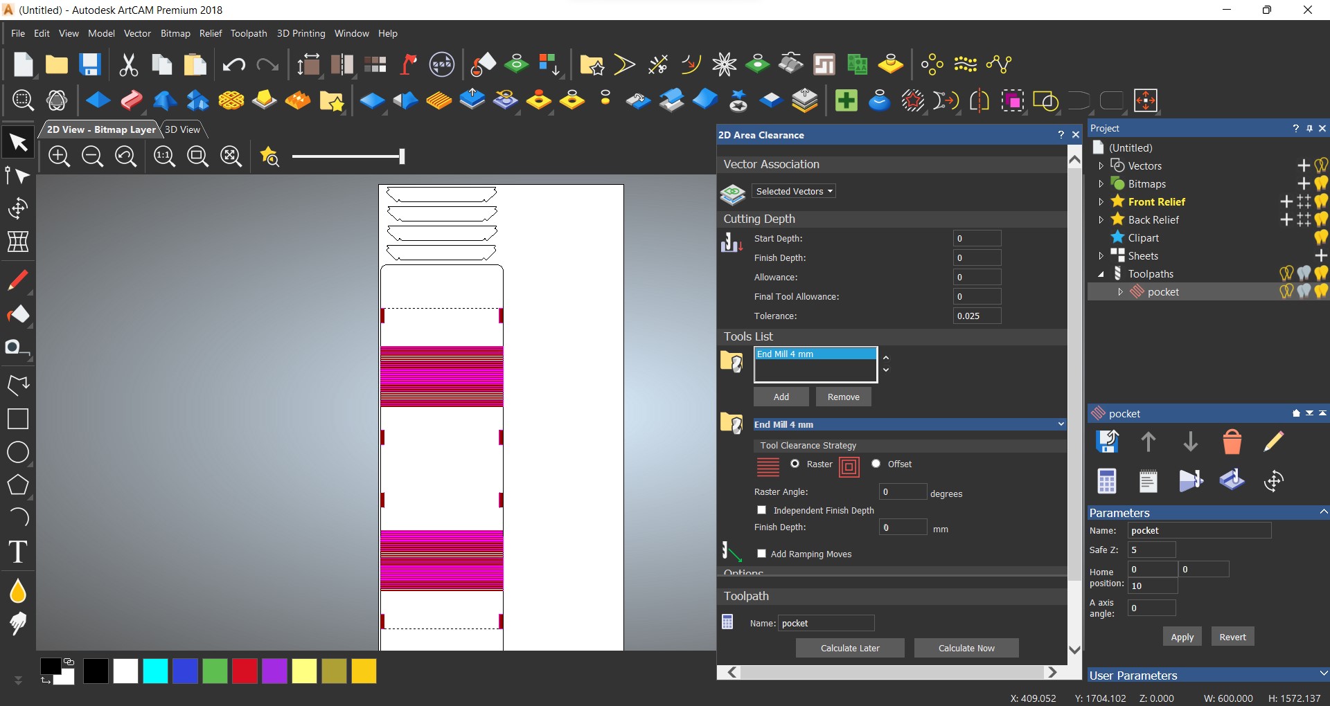
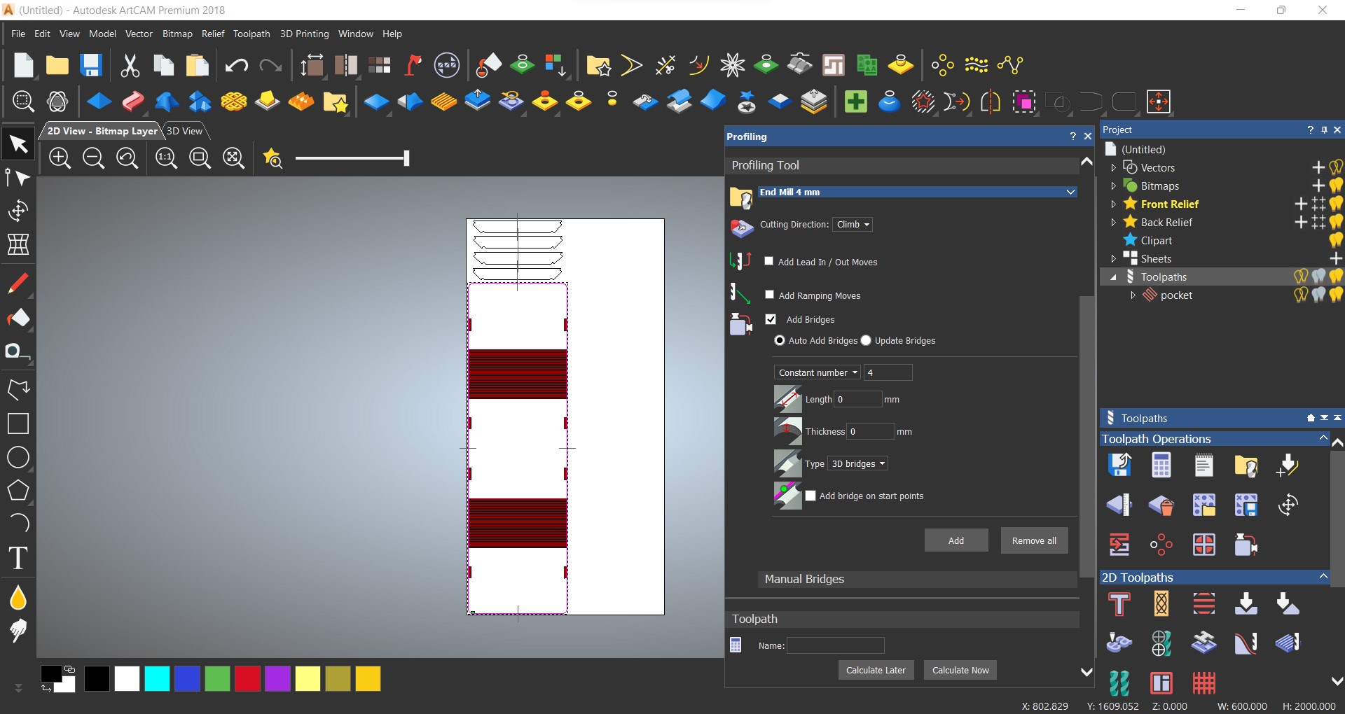
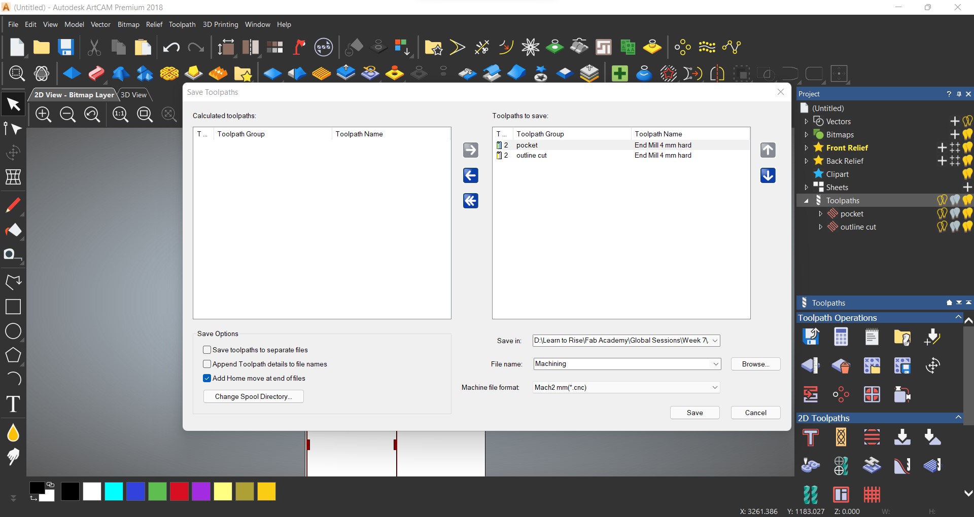
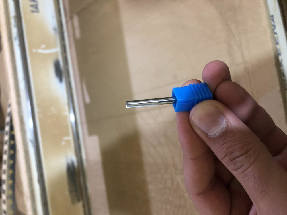
Toolpath generating
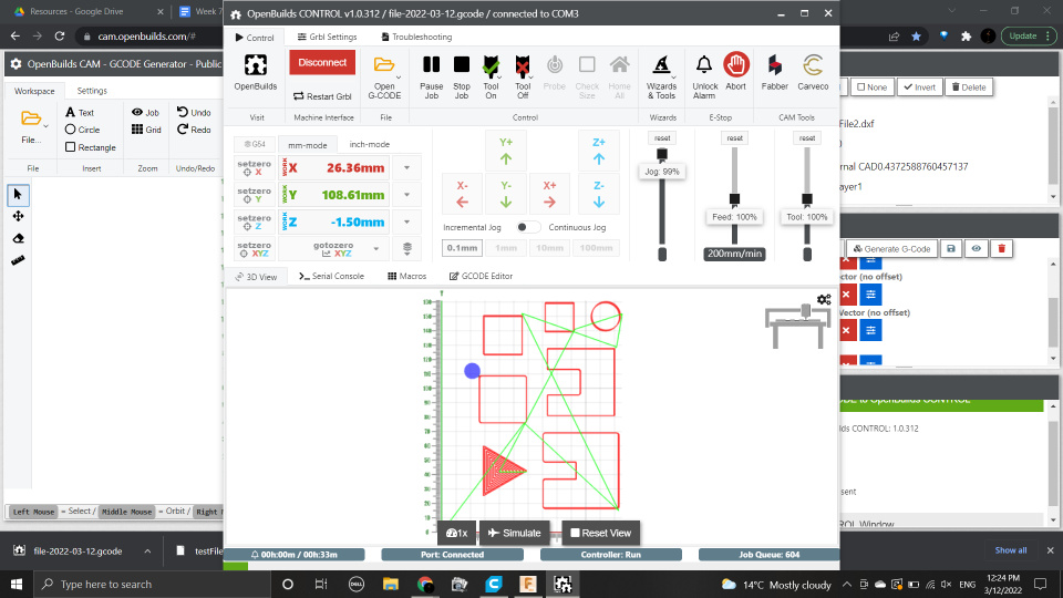
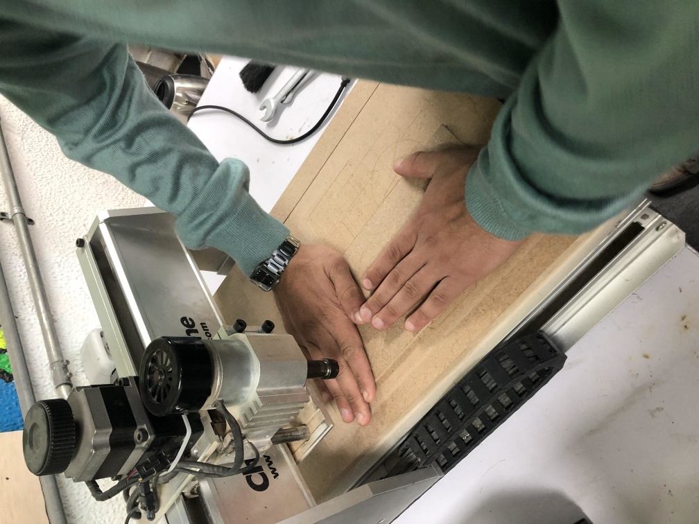
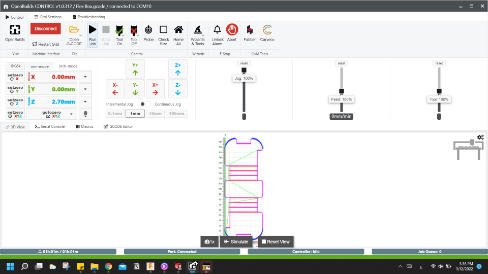
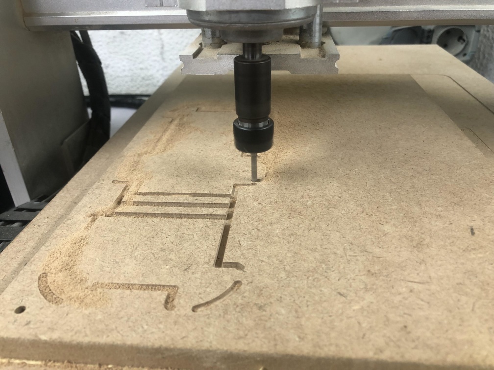
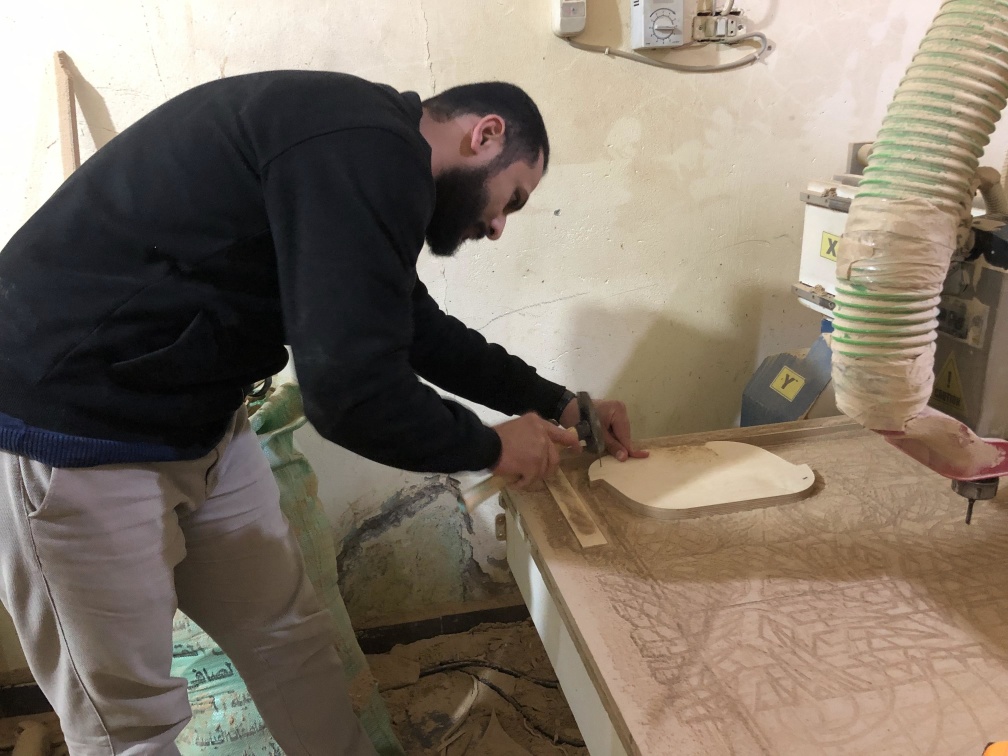
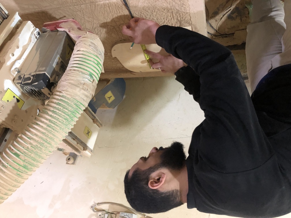
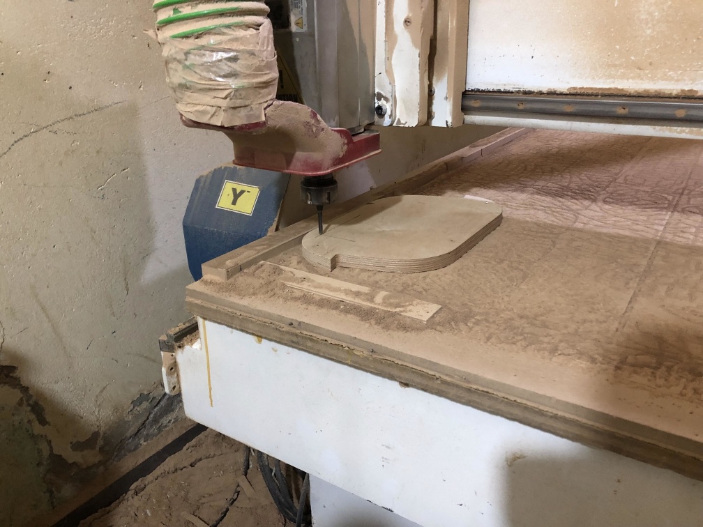
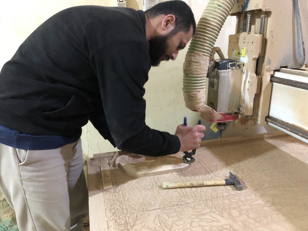
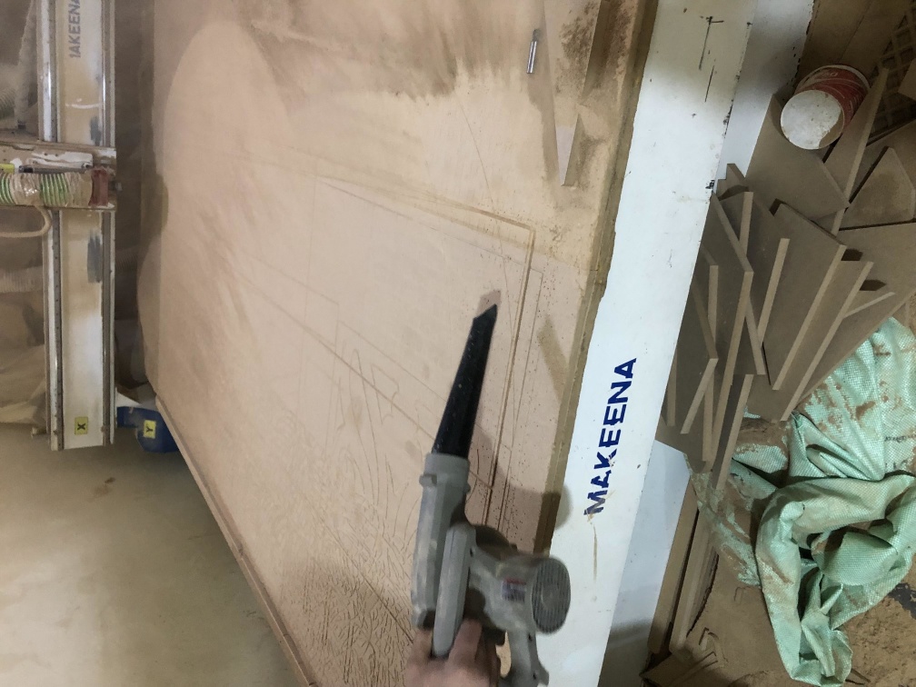
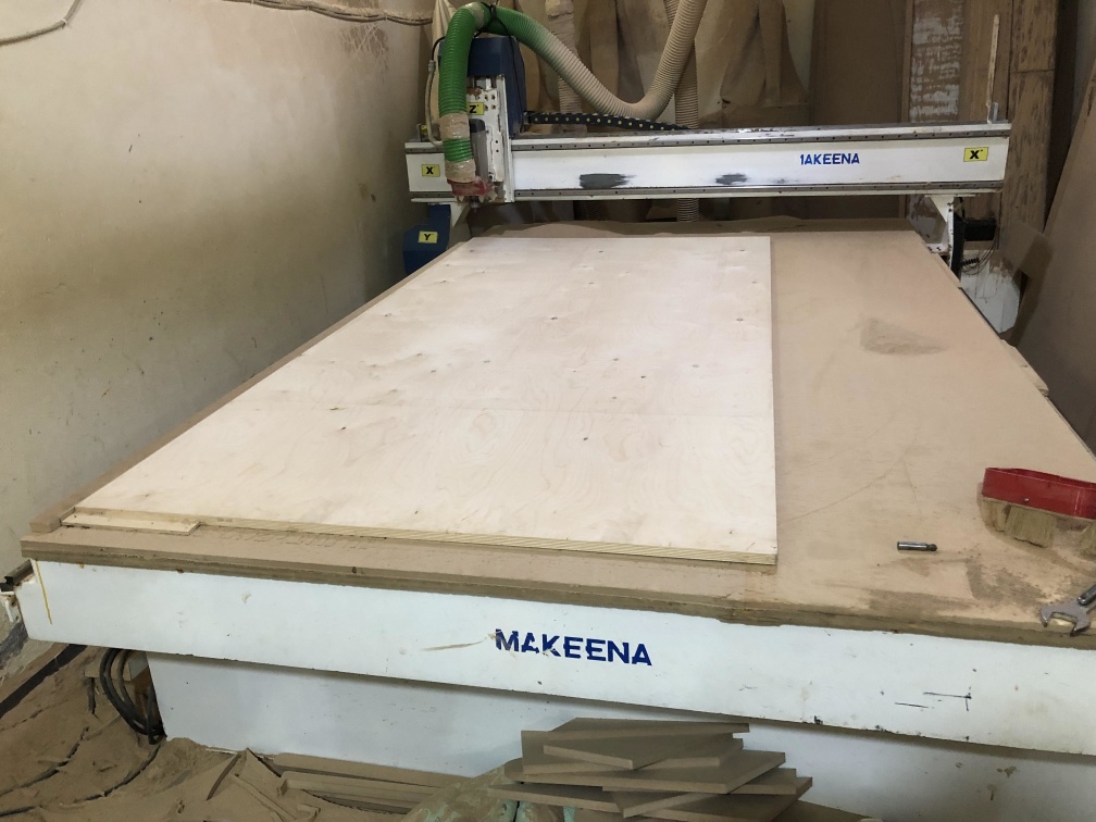
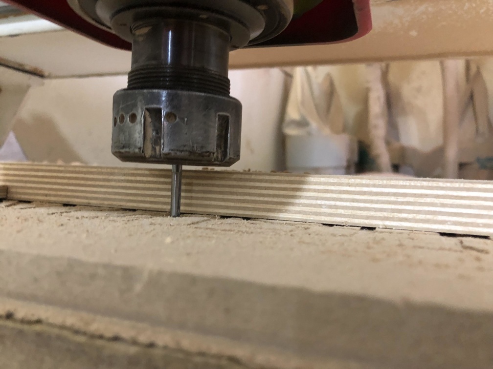
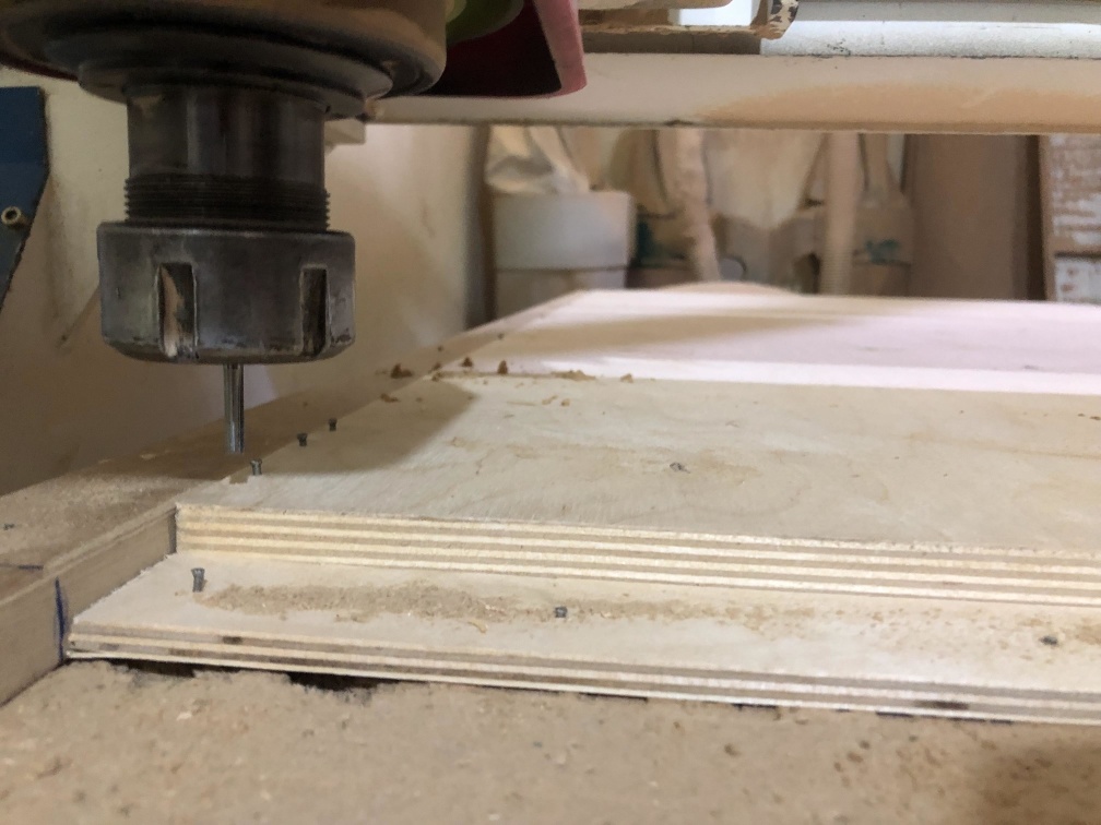
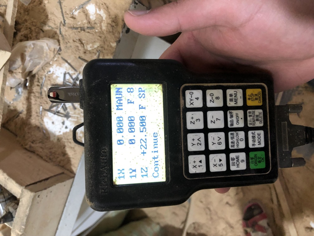
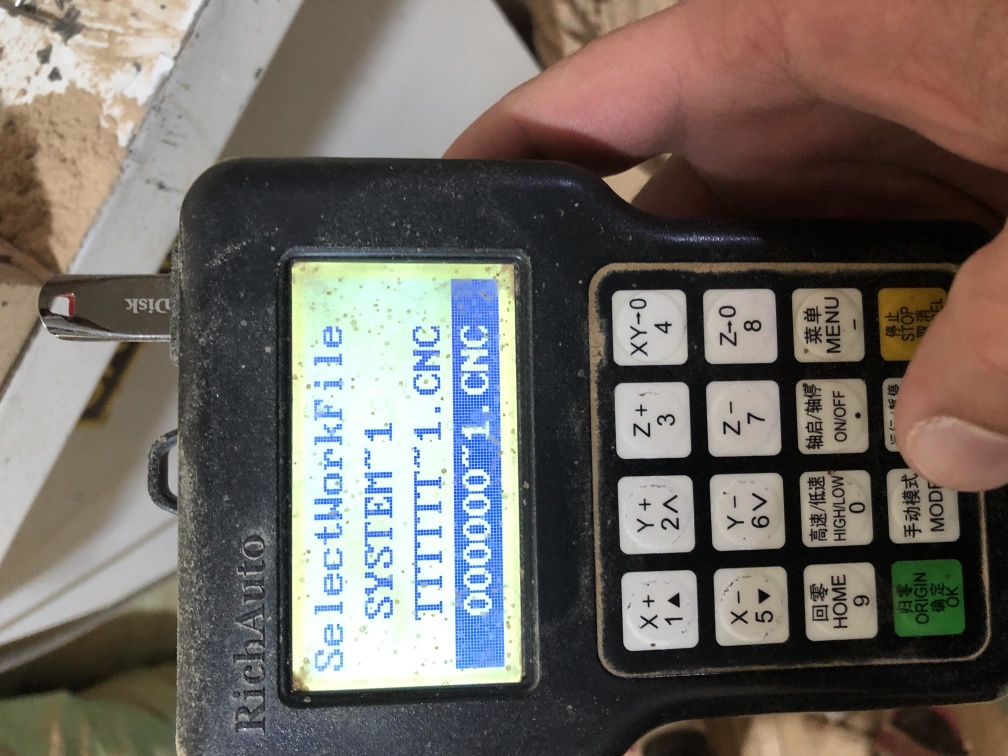
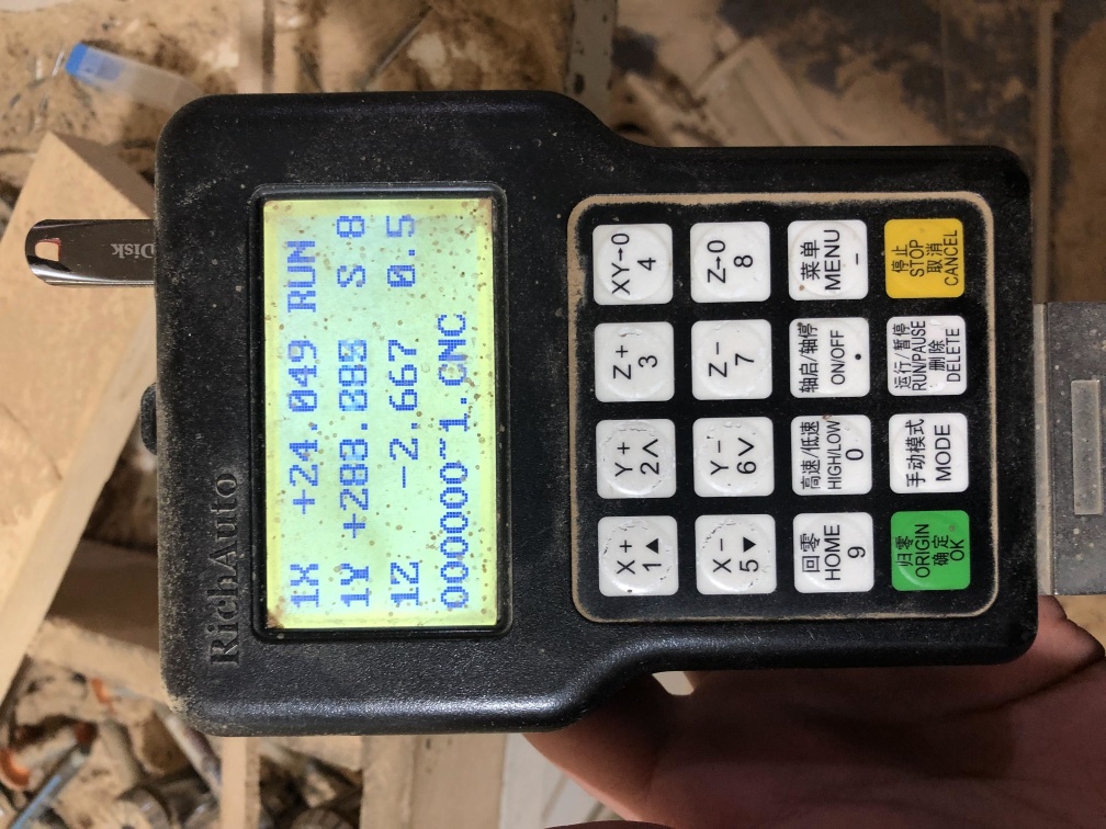
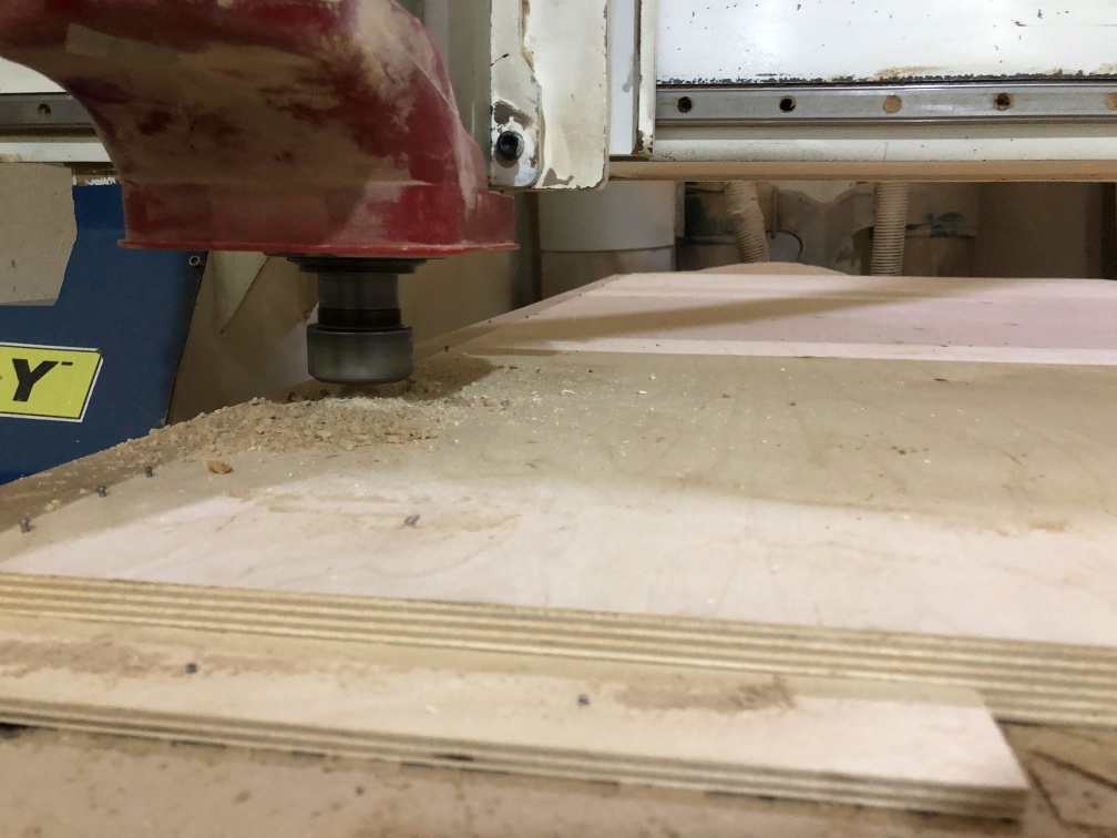
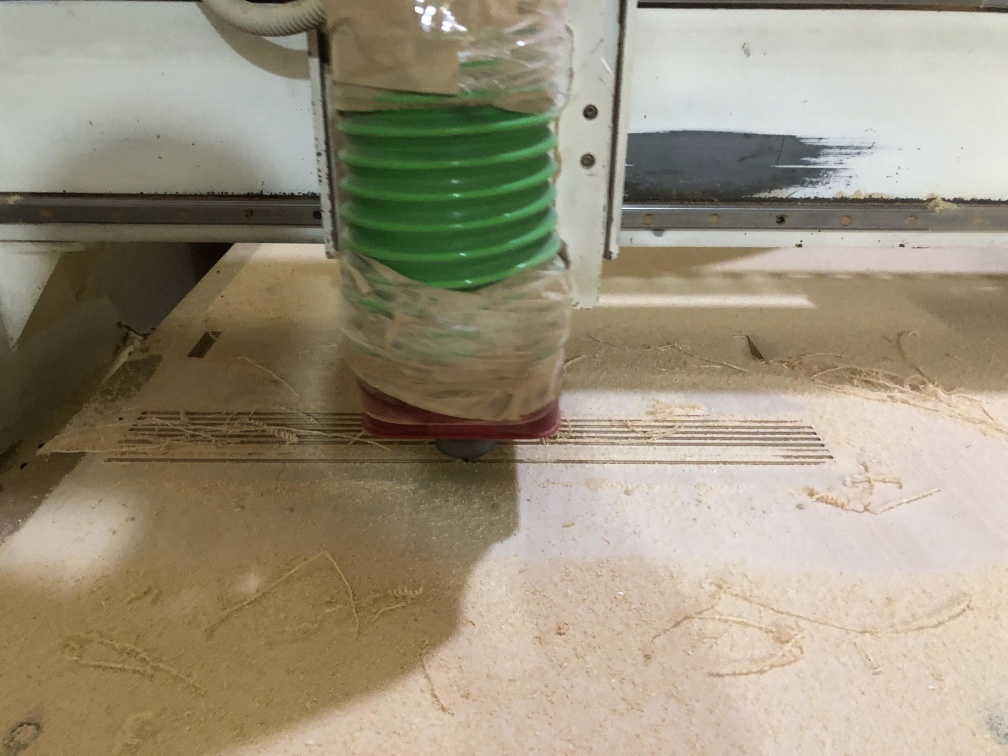
Machining
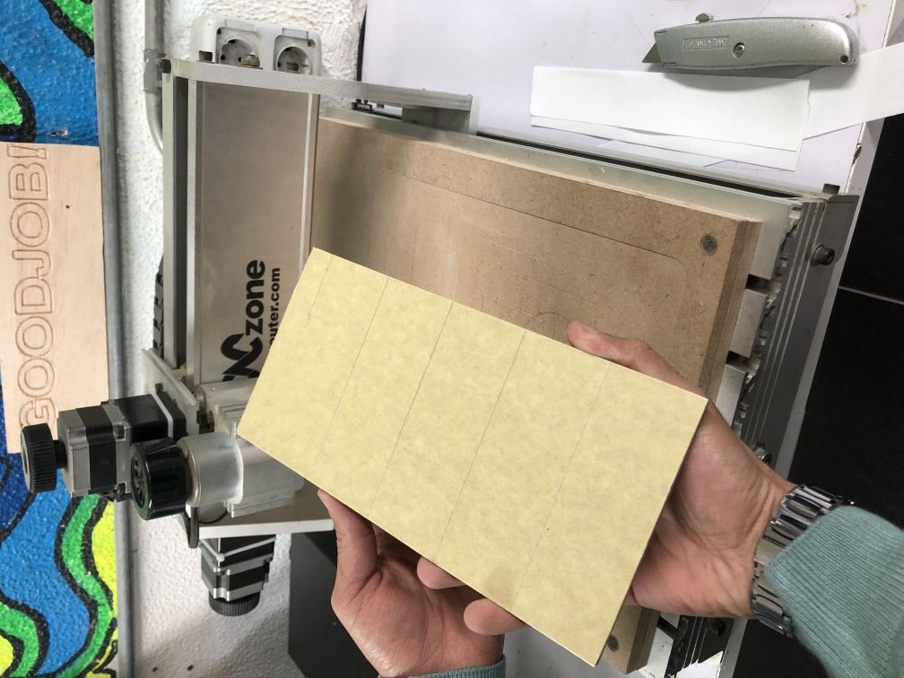
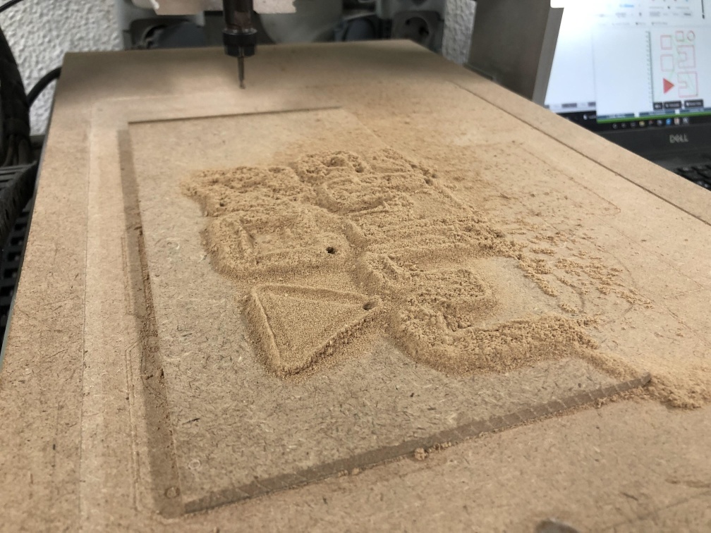
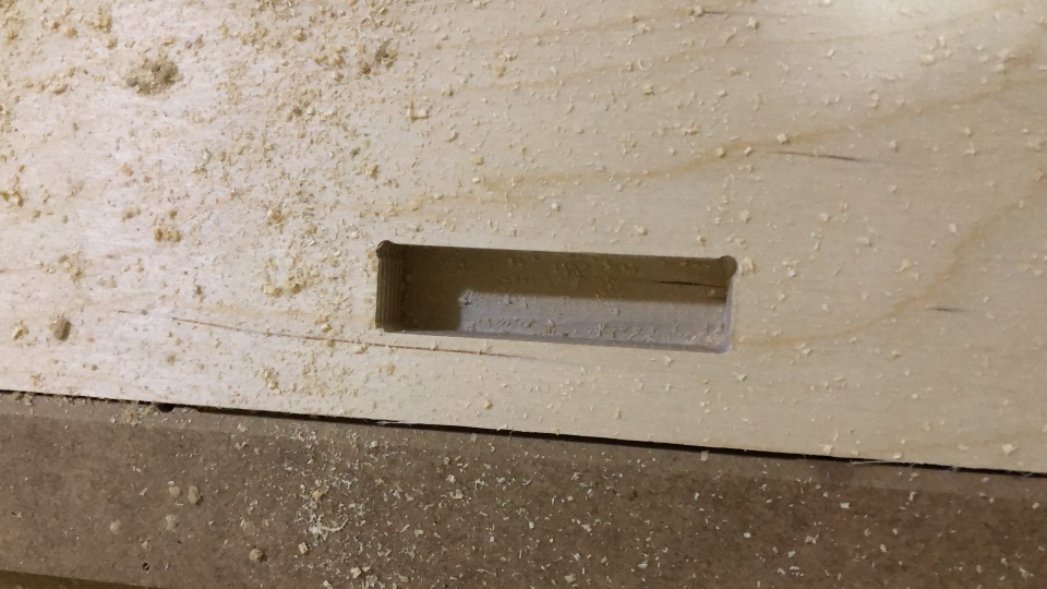
Practice
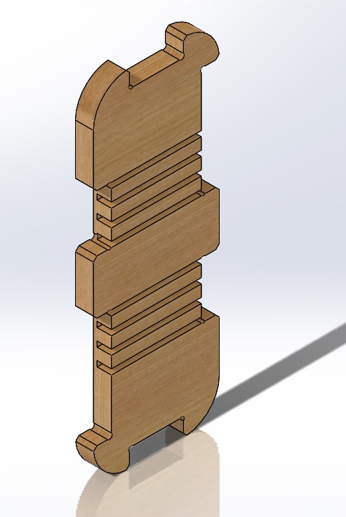
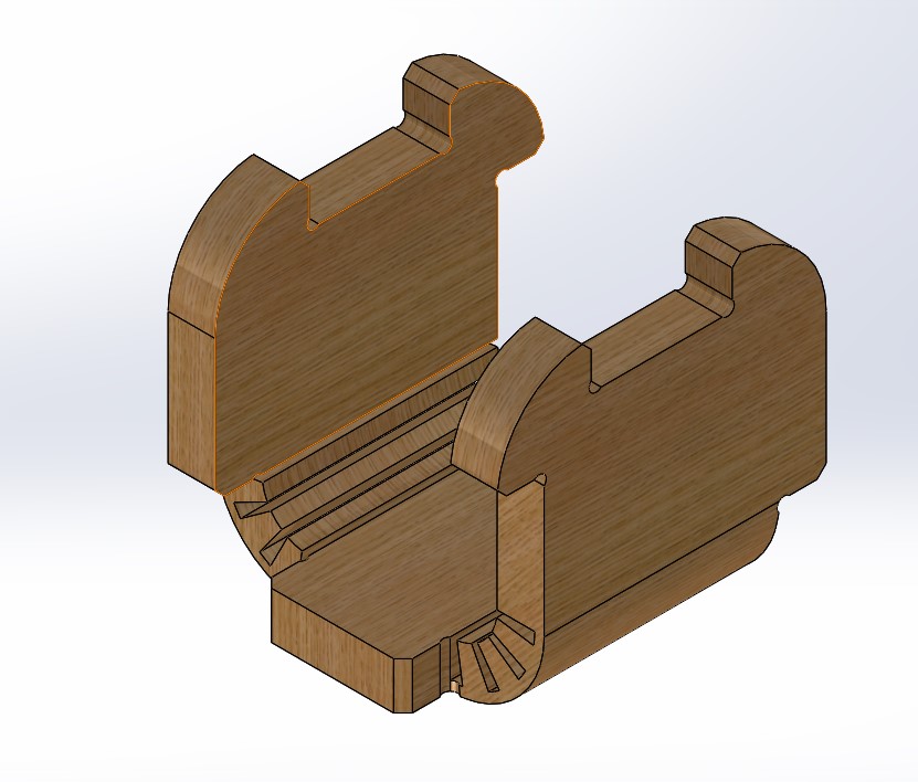
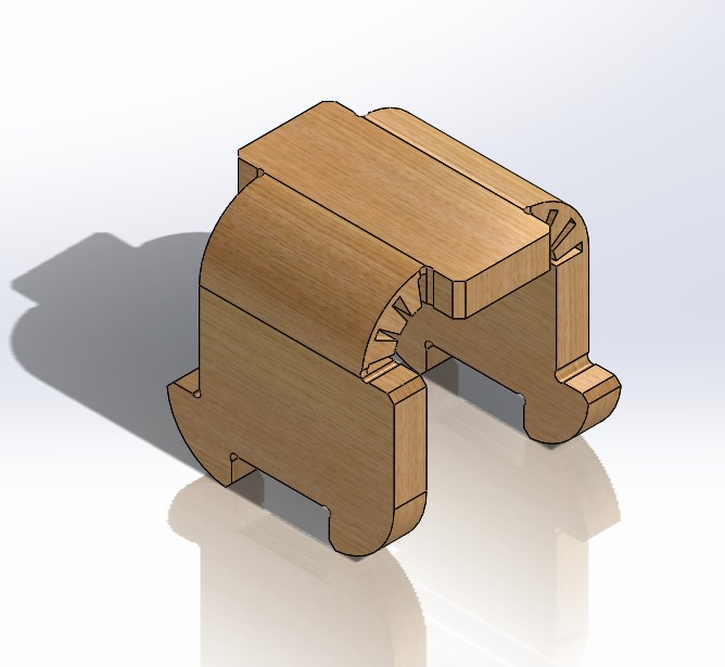
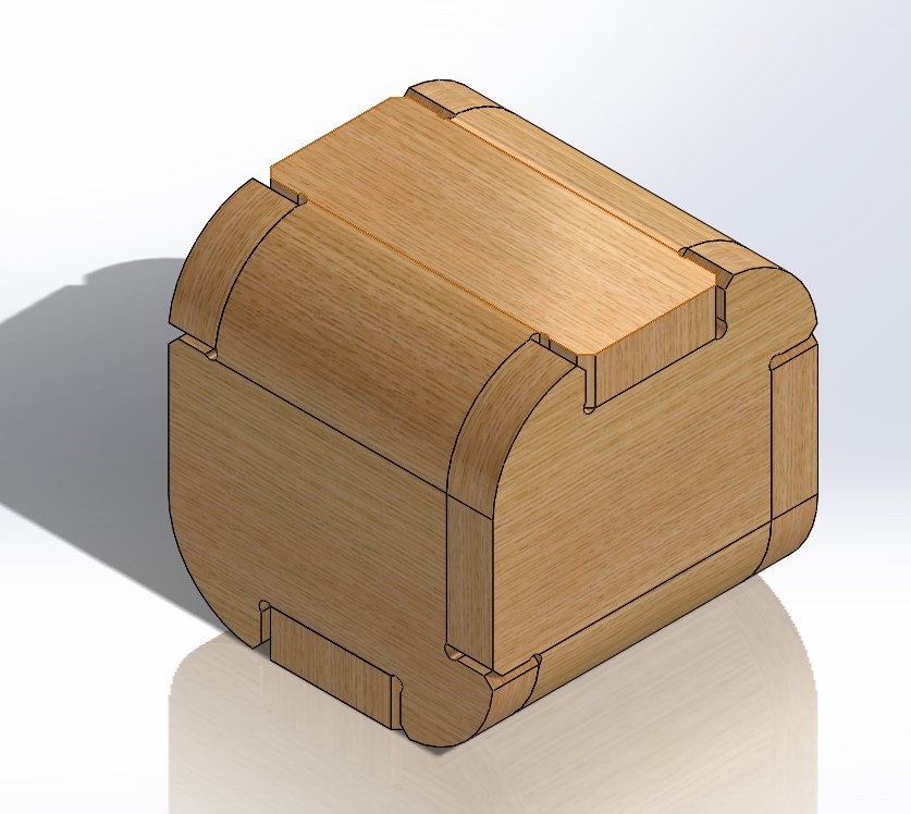
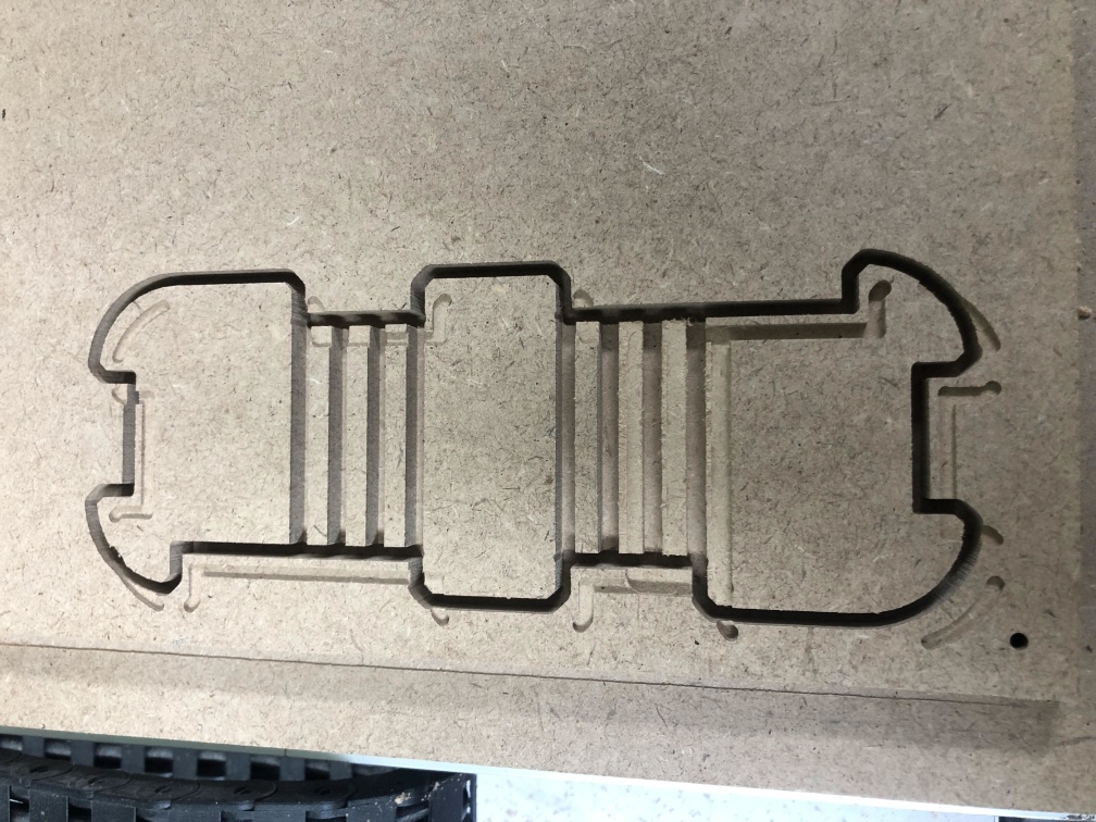
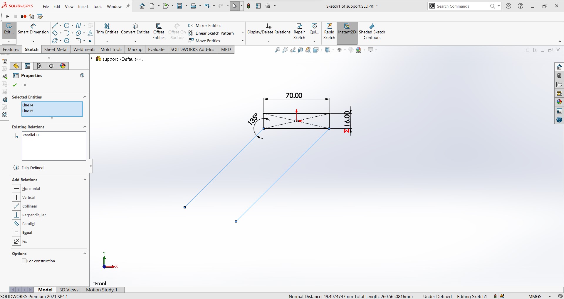
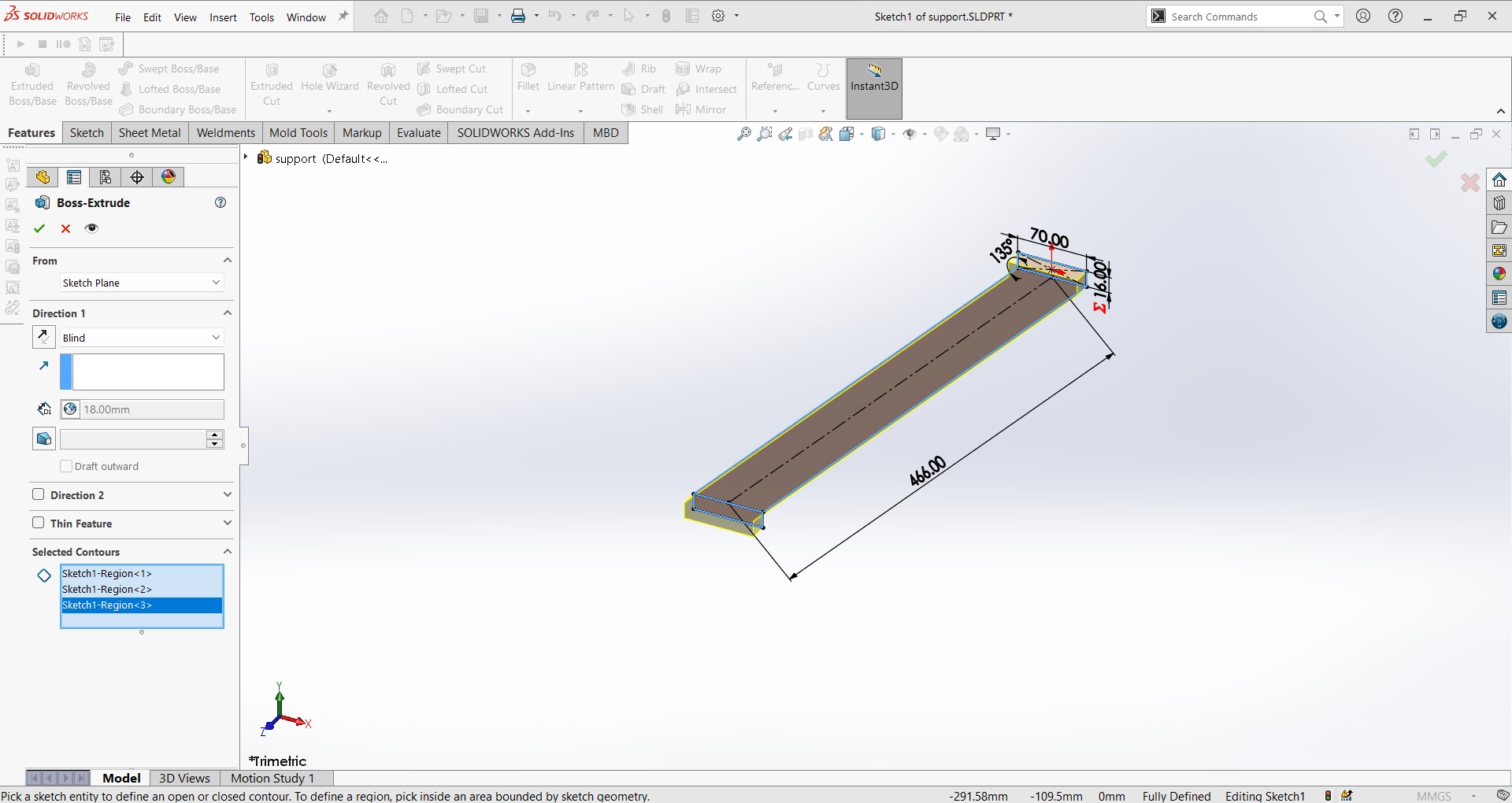
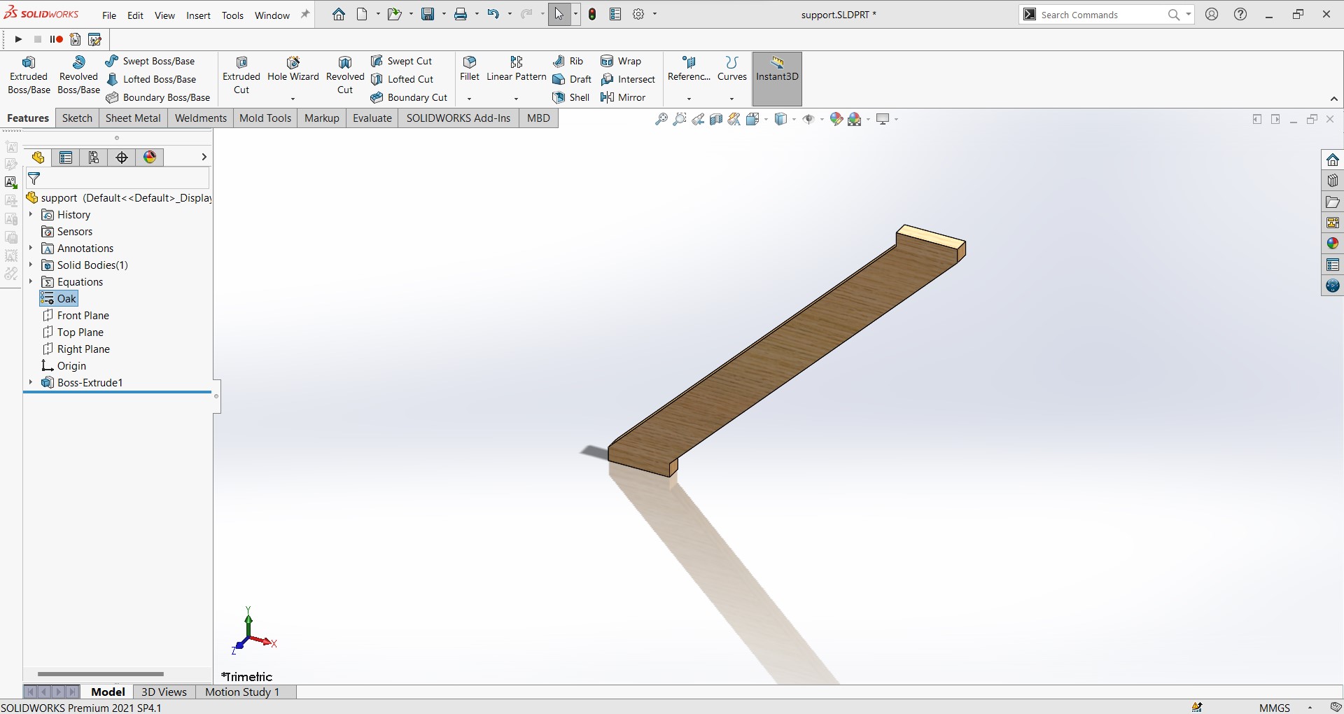
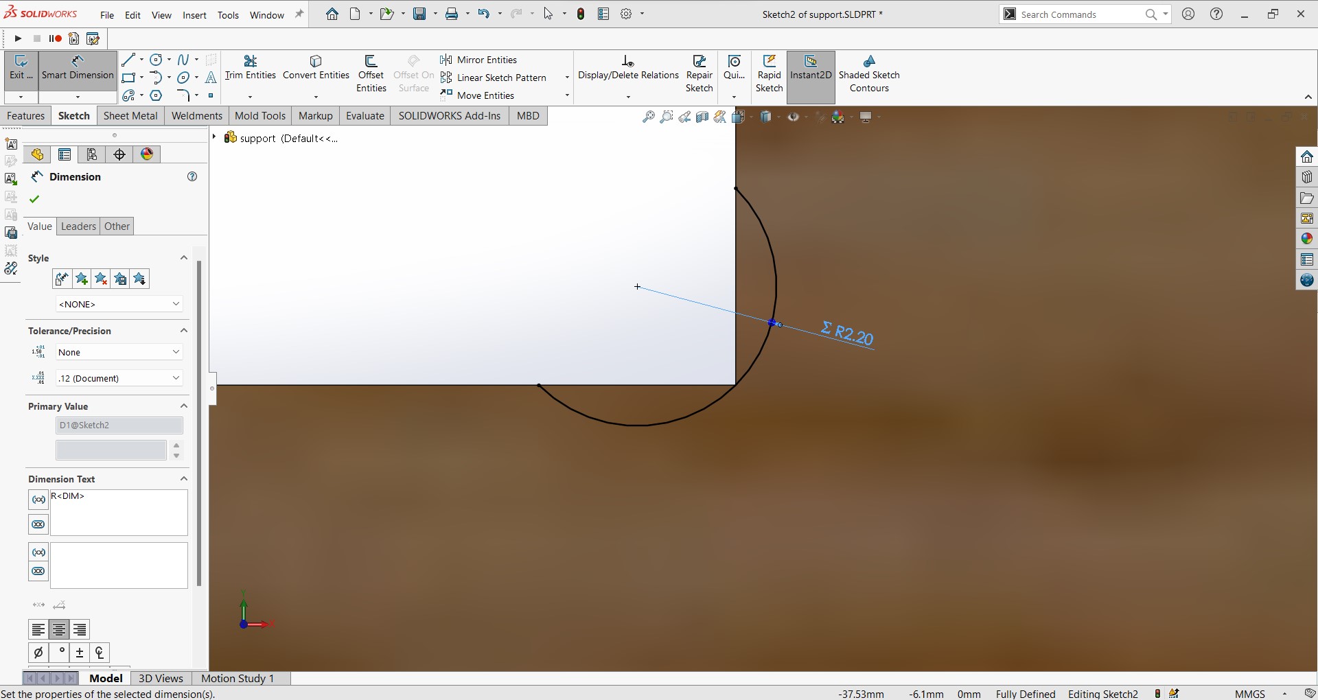
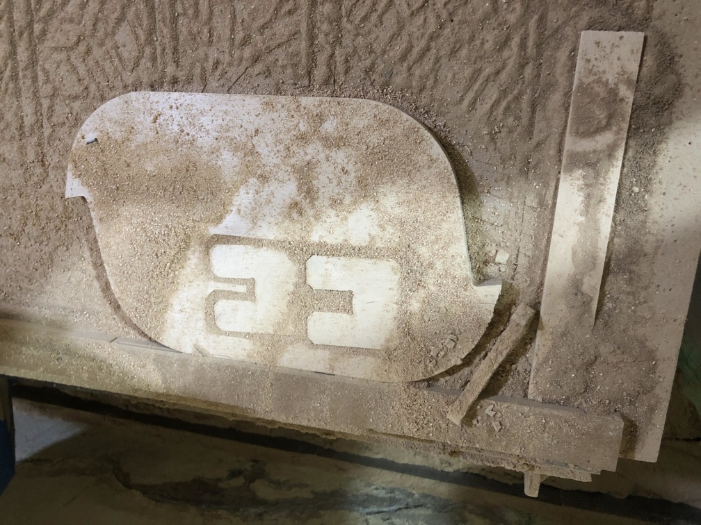
I had an idea so I started to design a small test part to check if it will work fine.
Design
Toolpath generating
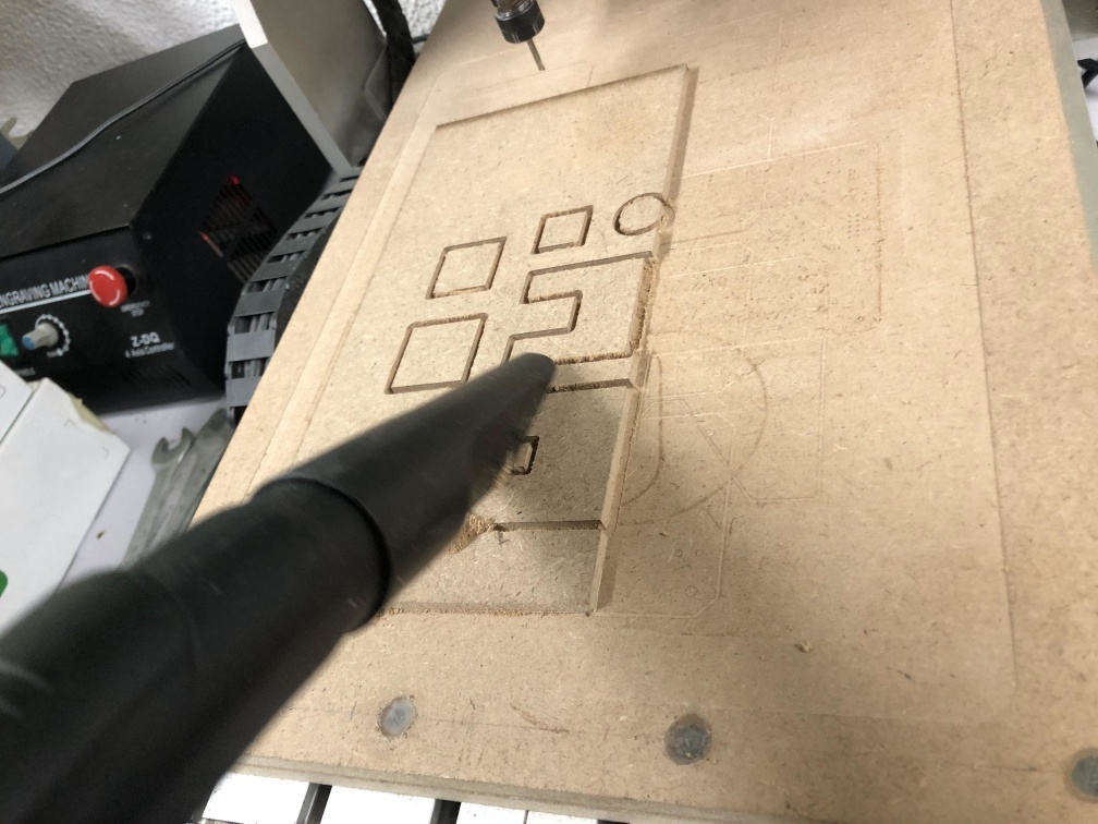
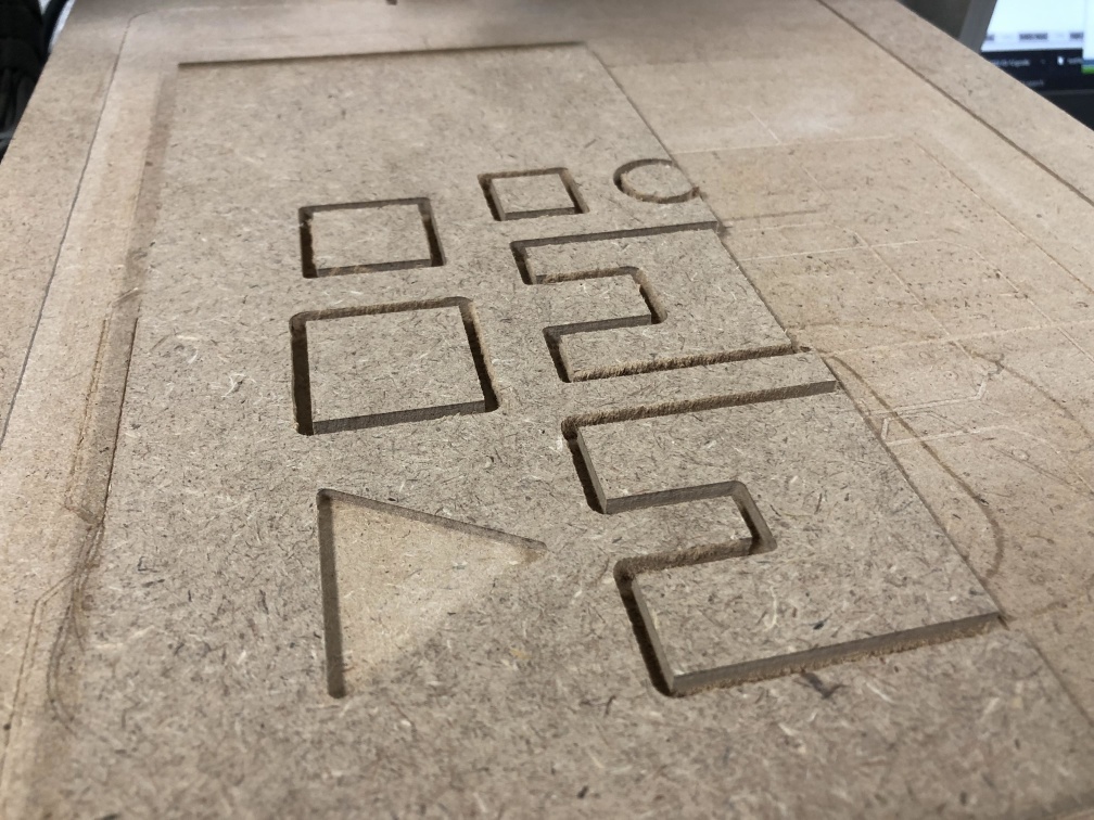
Machining
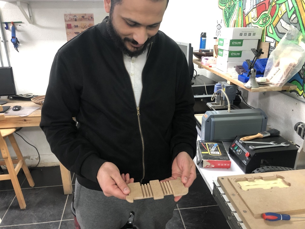
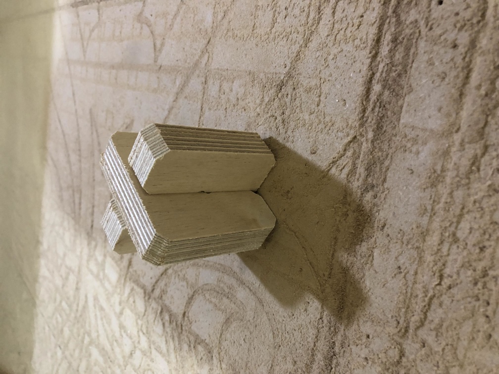
Post processing
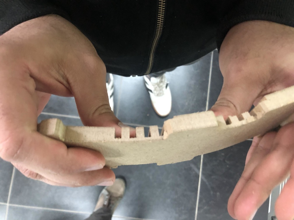
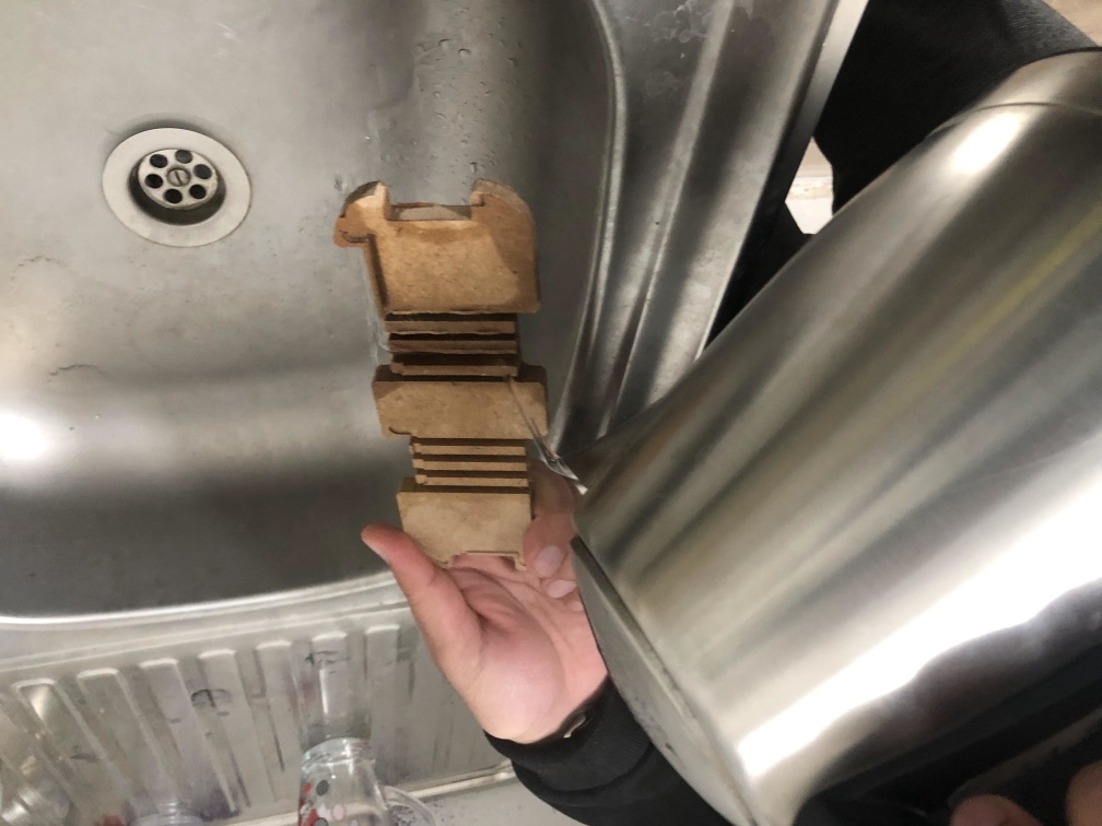
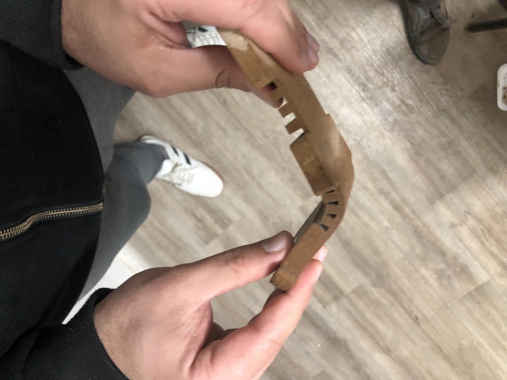
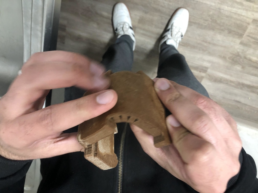
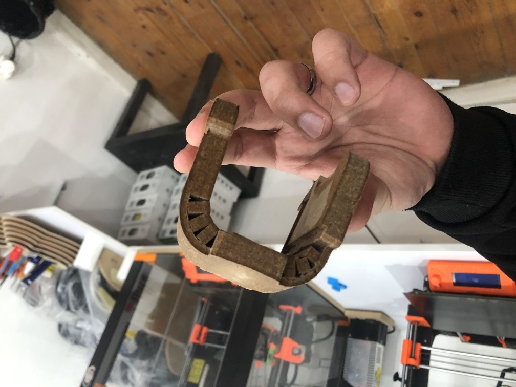
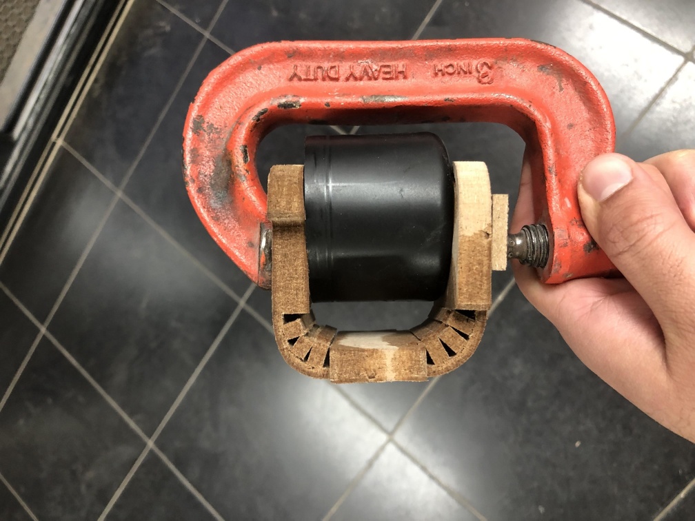
Conclusion: after this practice I'm sure now MDF isn't good for flexing so the suitable and available material is plywood So I decided to manufacture the assignment design on a plywood.
Individual Assignment
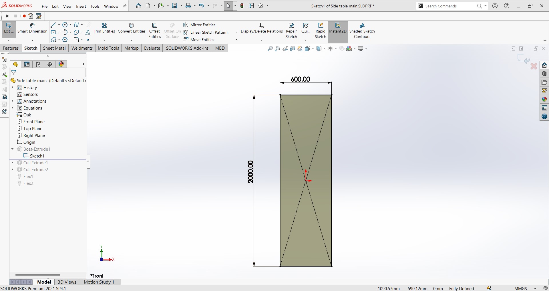
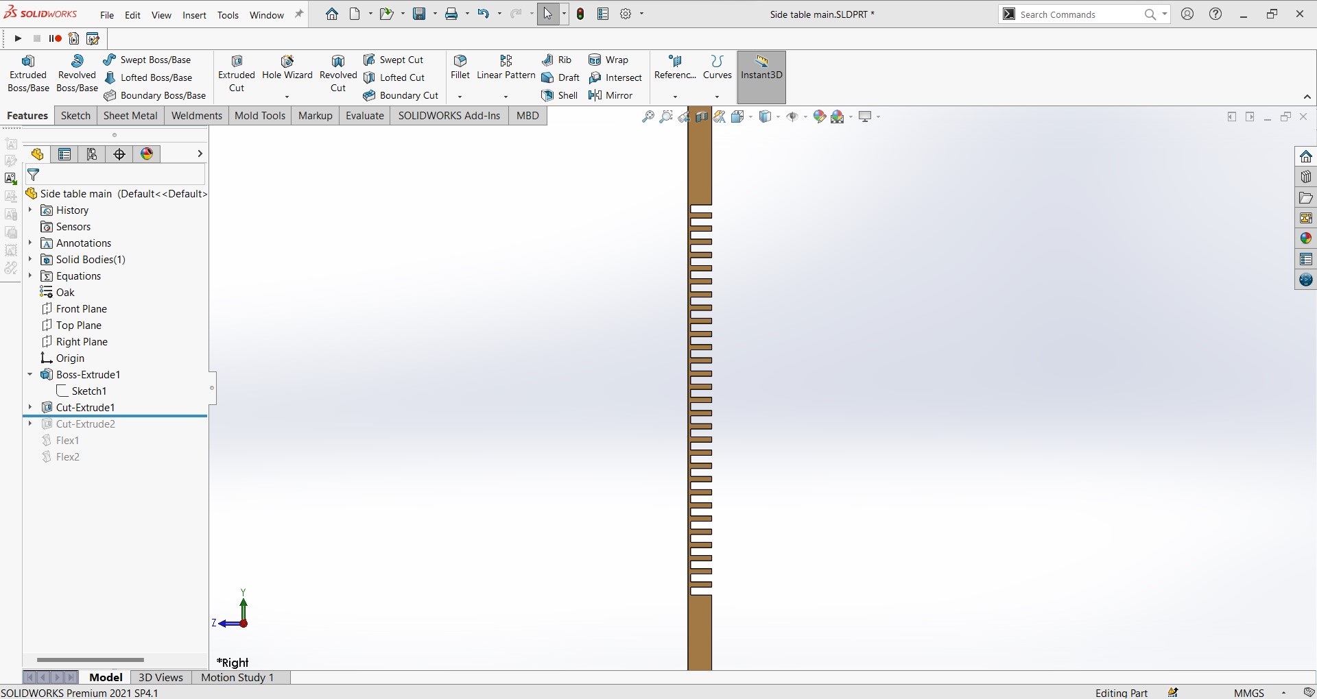
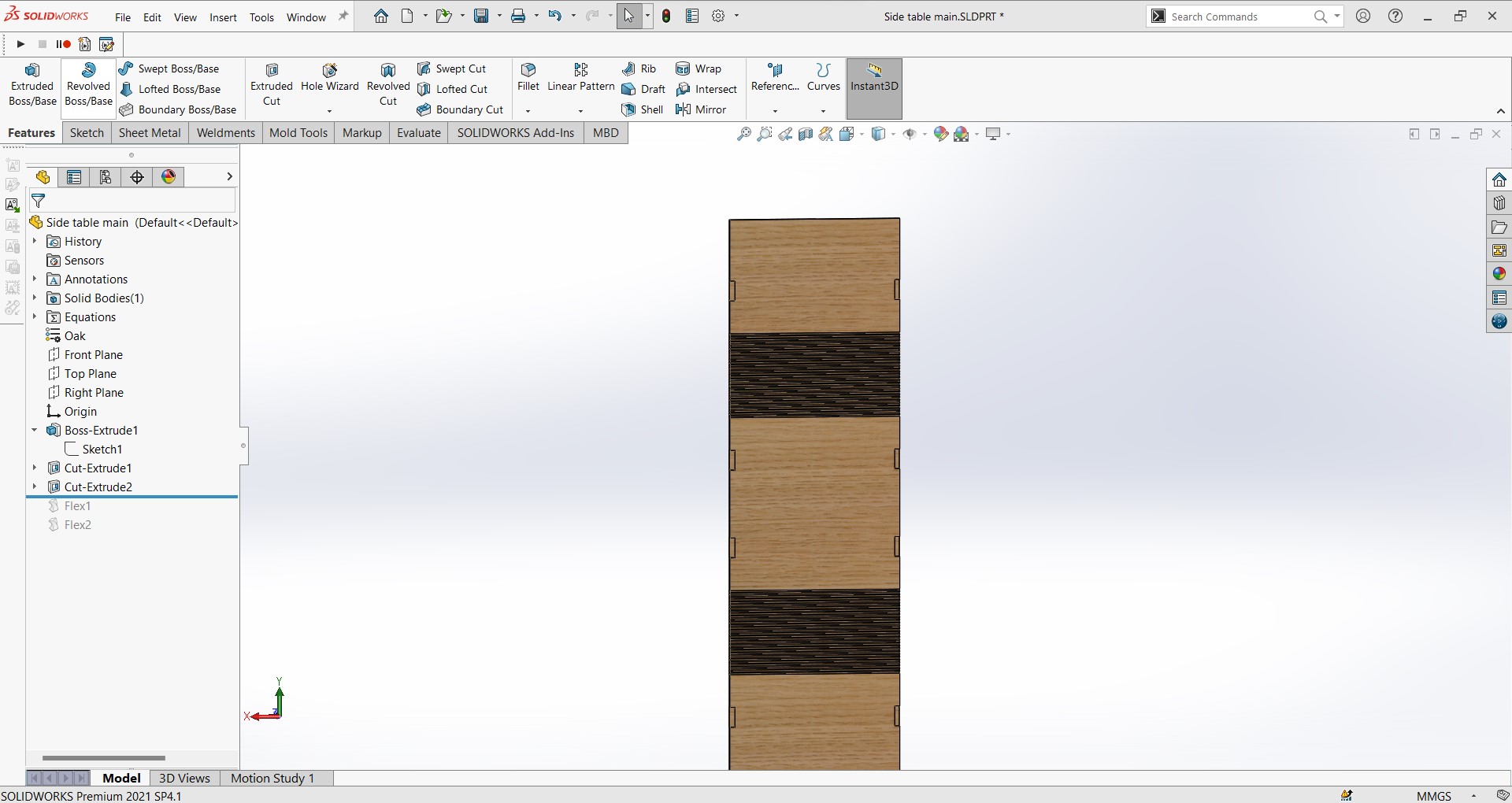
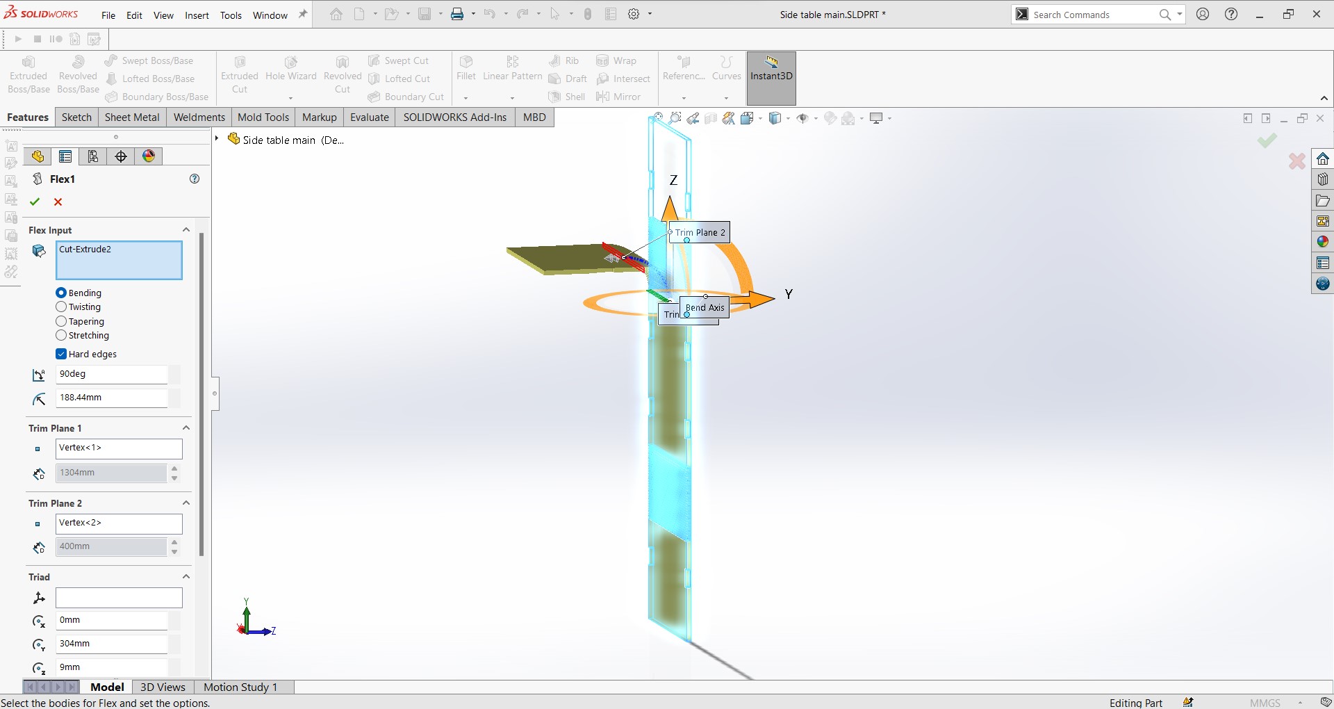
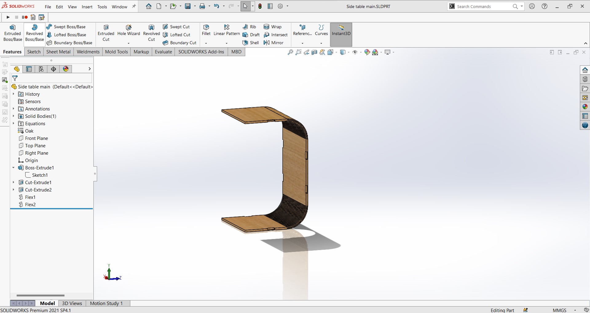
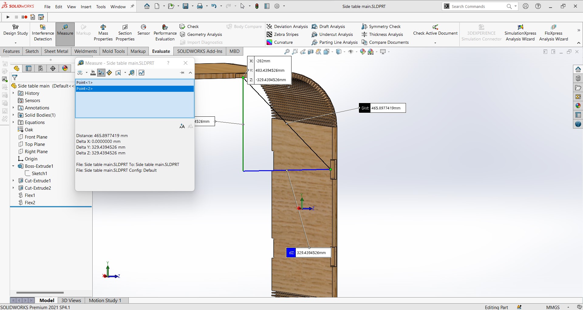
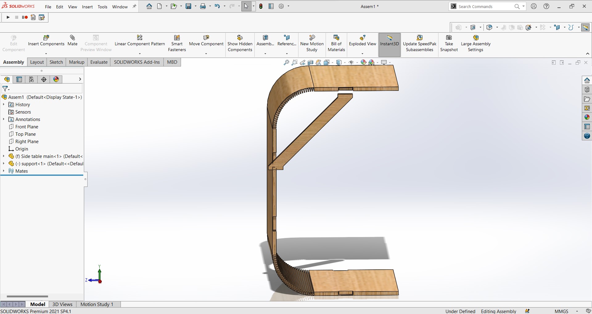
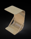
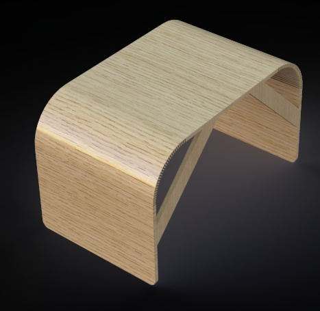
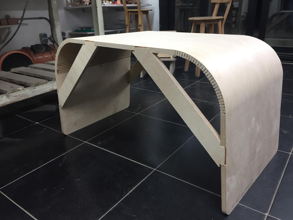
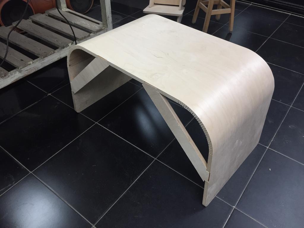
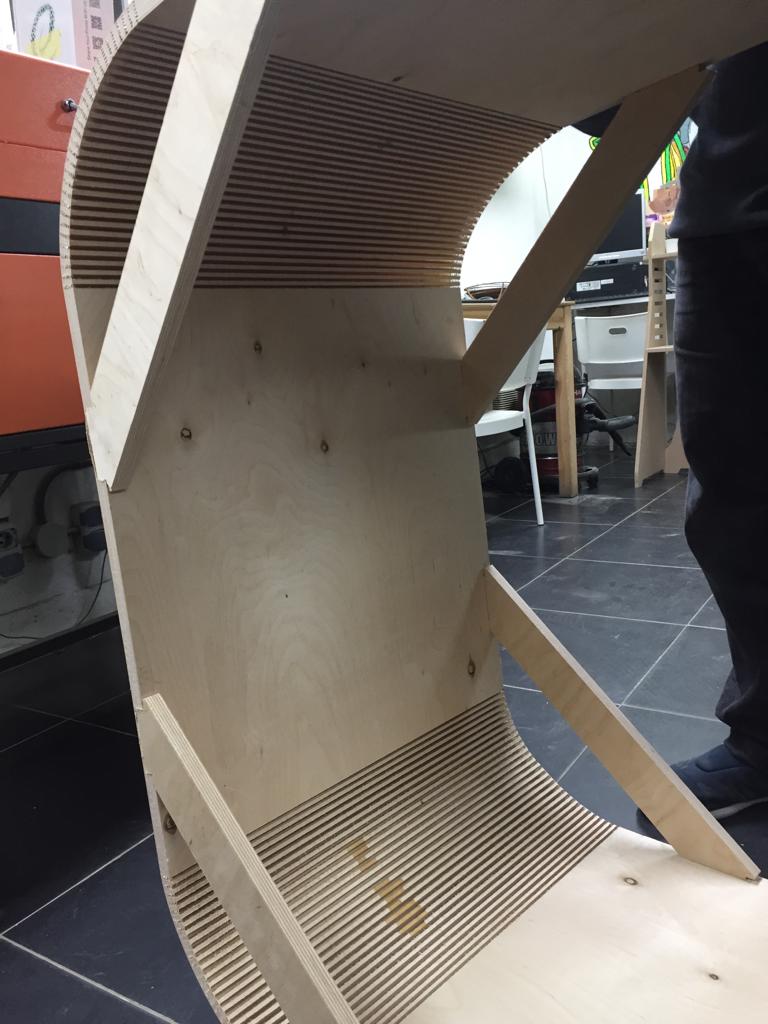
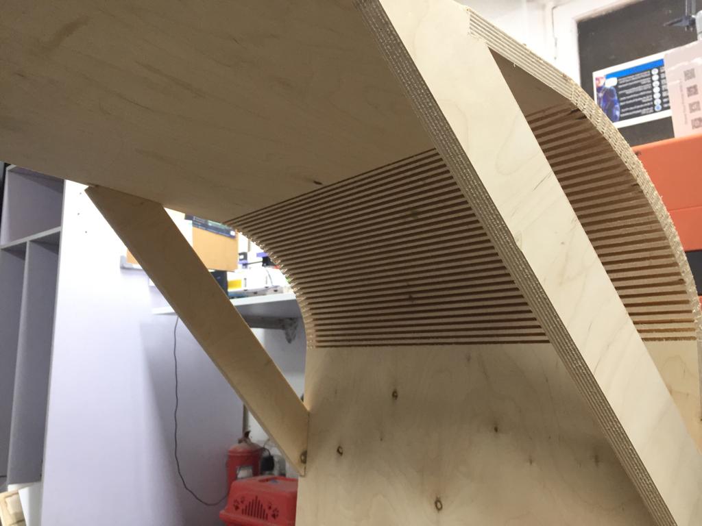
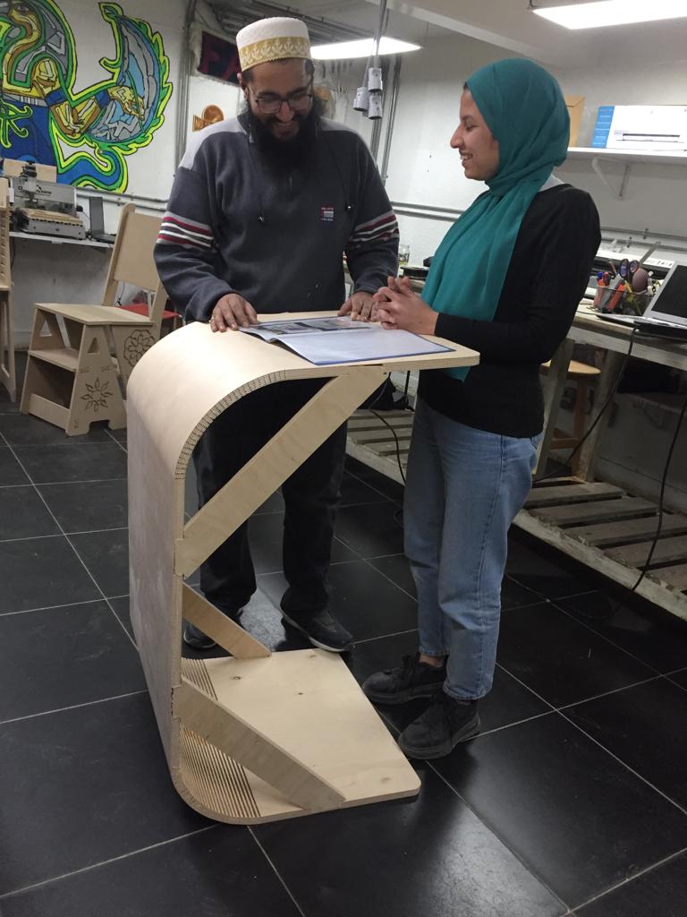
I wanted to desing a side table to be able to use it at home, also I wanted to apply flexing in my design and I did it.
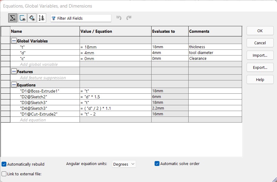
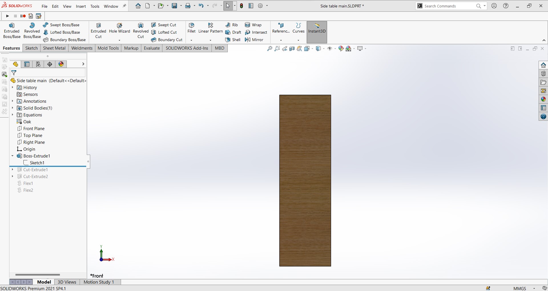
Design
To be continued but here's the photos for now.
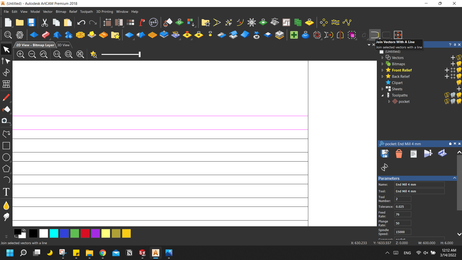
Toolpath generating
To be continued but here's the photos for now.
Machining
To be continued but here's the photos for now.


Post processing
To be continued but here's the photos for now, Gluing, sanding and varnishing in progress.
Challenges
To be continued