Electronics Design
Assignment requirements:
Group Assignment
- Use the test equipment in your lab to observe the operation of a microcontroller circuit board (in minimum, check operating voltage on the board with multimeter or voltmeter and use oscilloscope to check noise of operating voltage and interpret a data signal).
- Document your work (in a group or individually).
Individual Assignment
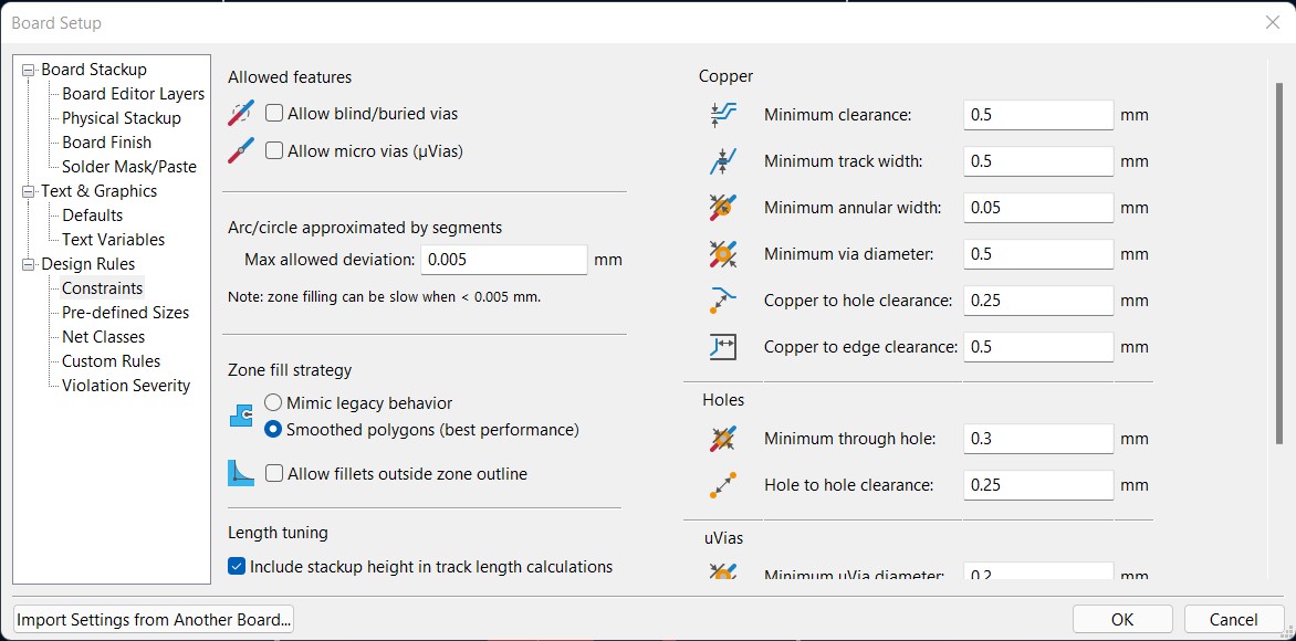
- Redraw one of the echo hello-world boards or something equivalent, add (at least) a button and LED (with current-limiting resistor) or equivalent input and output, check the design rules, make it, test it.
- 3D scan an object, try to prepare it for printing (and optionally print it).
Learning outcomes:
- Select and use software for circuit board design.
- Demonstrate workflows used in circuit board design.
Assessment criteria
- Linked to the group assignment page.
- Documented what you have learned in electronics design.
- Explain problems and how you fixed them, if you make a board and it doesn't work; fix the board (with jumper wires etc) until it does work.
- Included original design files (Eagle, KiCad, - whatever).
- Included a hero shot of your board.
- Loaded a program and tested if your board works.
Group Assignment
In this week we learned more about electronics testing tools, design tools and about electronics itself.
Oscilloscope
Individual Assignment
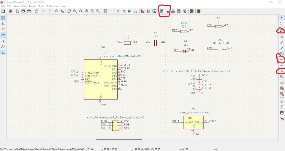
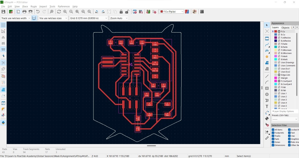
This Week I should redraw one of the echo hello-world boards, So first I decided to use KiCad software.
Circuit Design
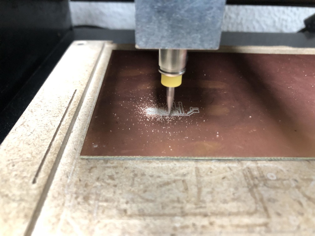
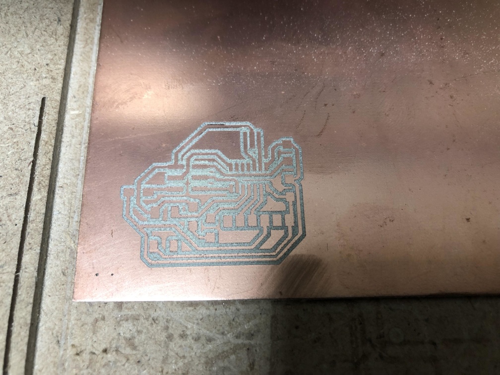
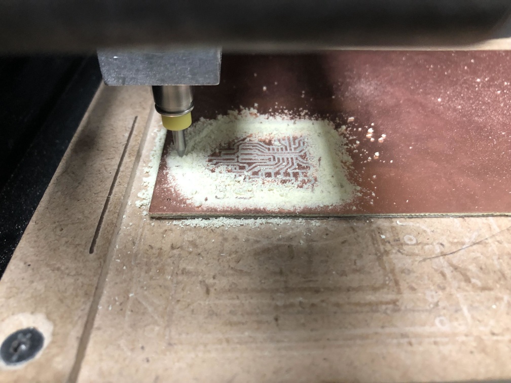
Manufacturing
I won't talk much about this as it's covered in Electronics Production week, I'm just repeating the process, but here's a few photos.
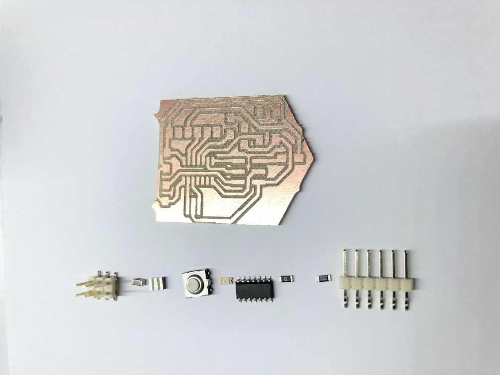
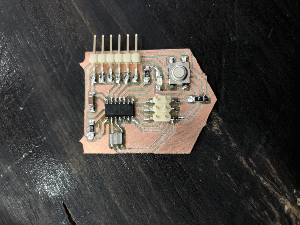
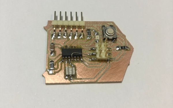
Soldering
Let's solder these components.
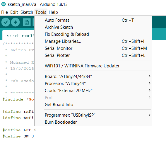
Programming
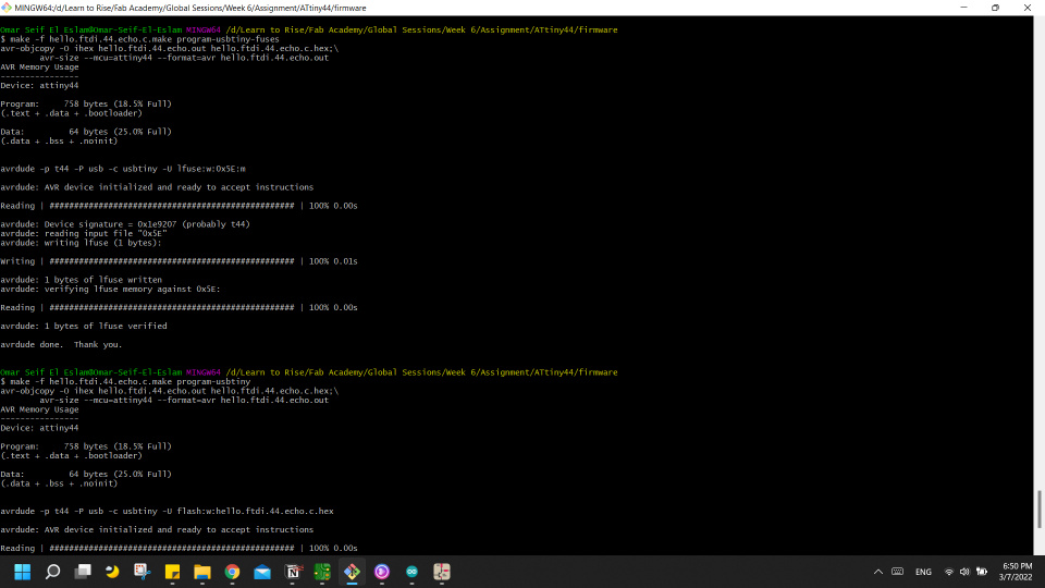
make -f hello.ftdi.44.echo.make and that created a HEX file and OUT file.
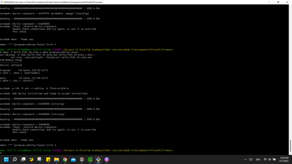
make -f hello.ftdi.44.echo.make program-usbtiny-fuses while connecting my FabISP to my laptop and connection it with the hello echo board using ISP 6-pin connector.
I got an error here but I will take about that in Challenges section
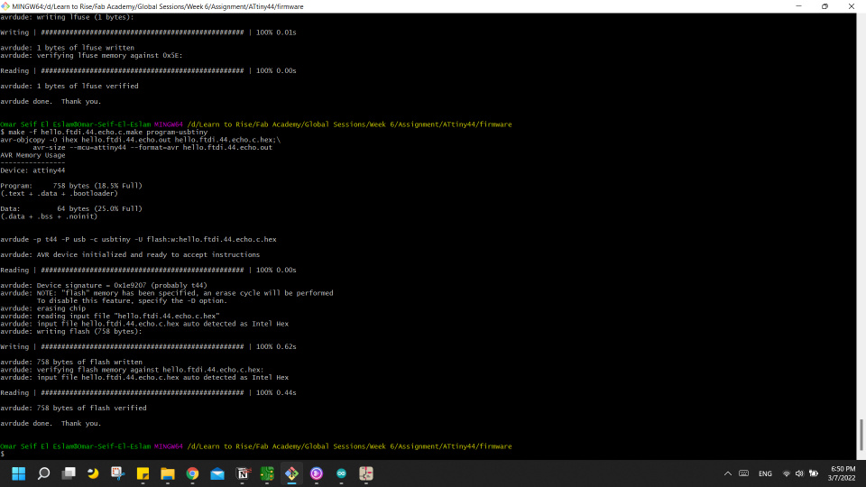
make -f hello.ftdi.44.echo.make program-usbtiny
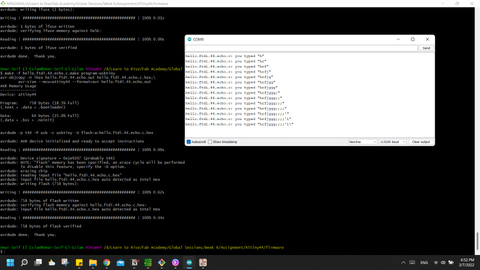
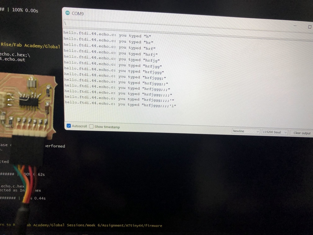
Testing
pinMode(SW, INPUT_PULLUP);
Challenges
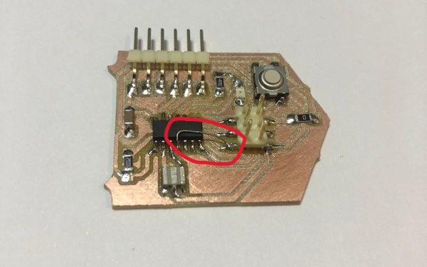
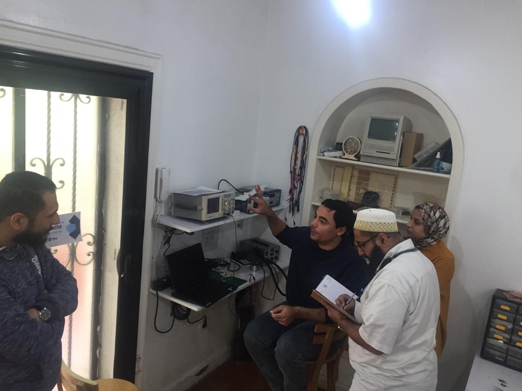
I have got an error that means my board can't be detected, with help of our instructor using a multimeter we discovered that the RST pin in the ATtiny44 chip isn't connected and that was a mistake in my design, so instead of making another board we put a jumper above the chip and it worked.