3D Scanning and Printing
Assignment requirements:
Group Assignment
- Test the design rules for your 3D printer(s).
- Document your work and explain what are the limits of your printer(s) (in a group or individually).
Individual Assignment
- Design and 3D print an object (small, few cm3, limited by printer time) that could not be easily made subtractively.
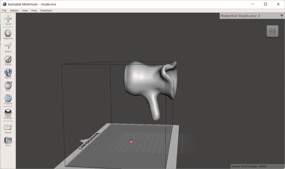
- 3D scan an object, try to prepare it for printing (and optionally print it).
Learning outcomes:
- Identify the advantages and limitations of 3D printing.
- Apply design methods and production processes to show your understanding of 3D printing.
- Demonstrate how scanning technology can be used to digitize object(s).
Assessment criteria
- Linked to the group assignment page.
- Explained what you learned from testing the 3D printers.
- Documented how you designed and made your object and explained why it could not be easily made subtractively.
- Documented how you scanned and prepared an object (for 3D printing).
- Included your original design files for 3D printing (both CAD and common format for 3D printing).
- Included your hero shots.
Group Assignment
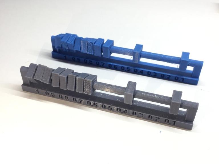
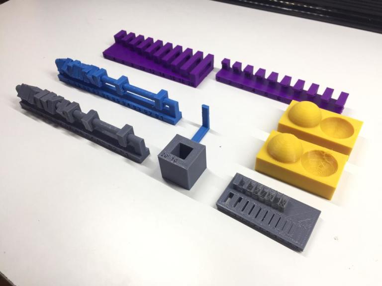
In this week we want to test the design rules for our 3D printers.
We Have Prusa 3D printers Mk3 and Mk2.
Using Ultimaker Cura slicer software, we have prepared the stl files that will help us define the 3D printer rules.
I will mention the result of each.
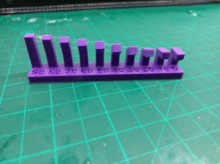
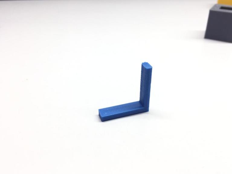
Overhang
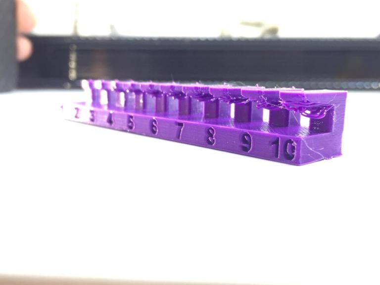
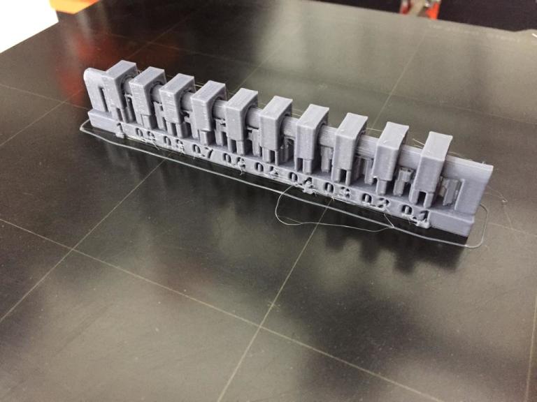
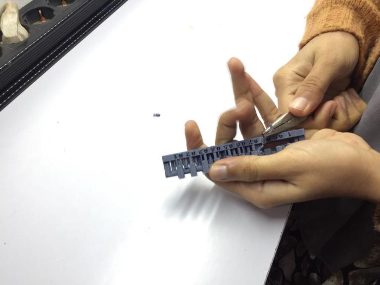
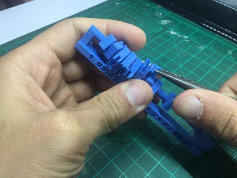
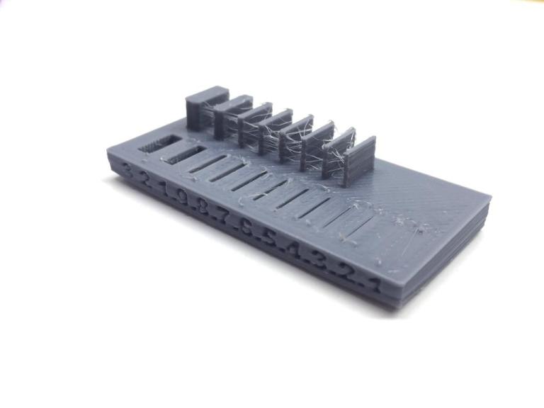
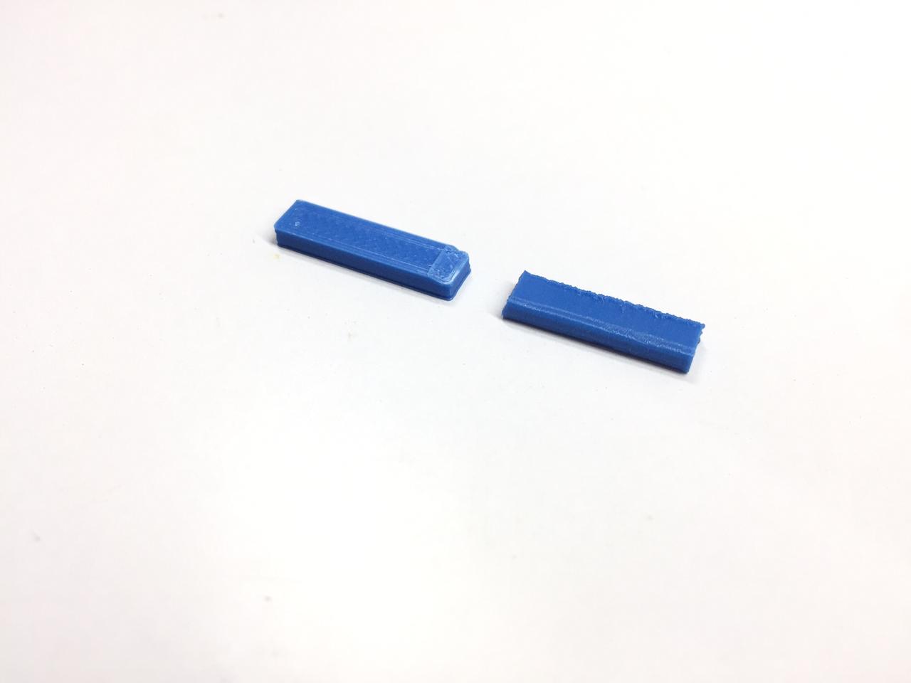
Clearance
Angle
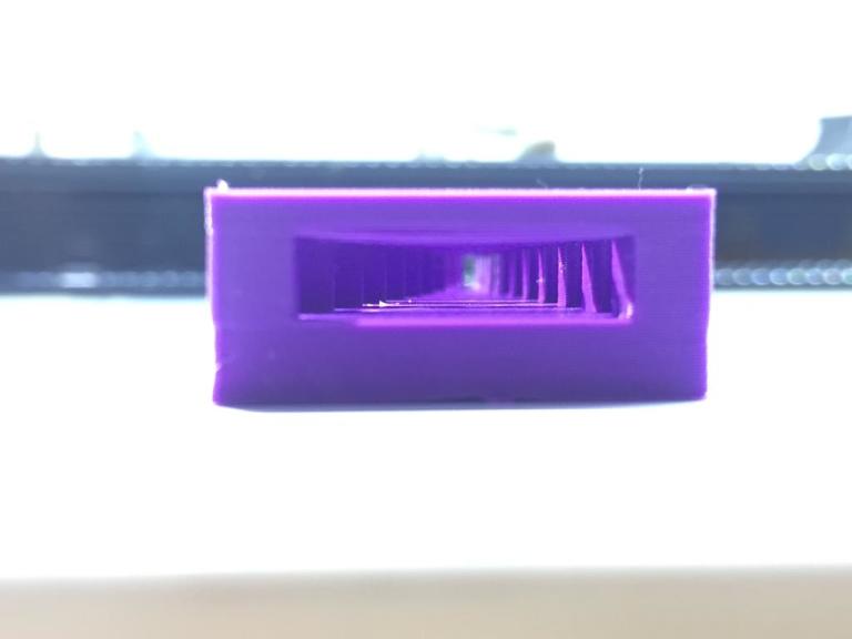
Bridging
Wall Thickness
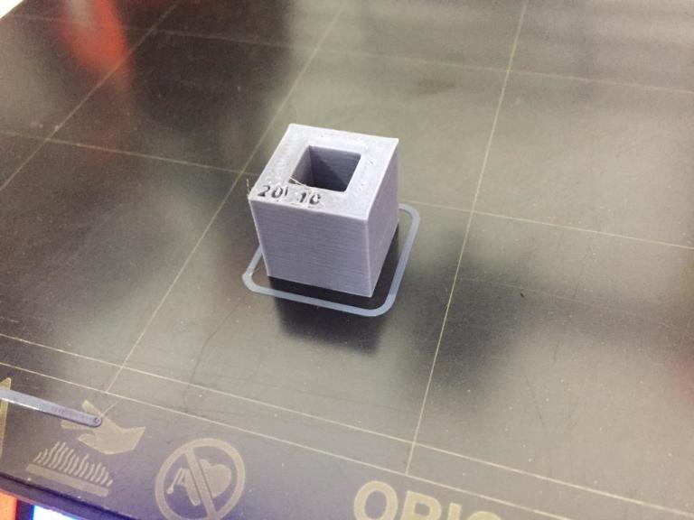
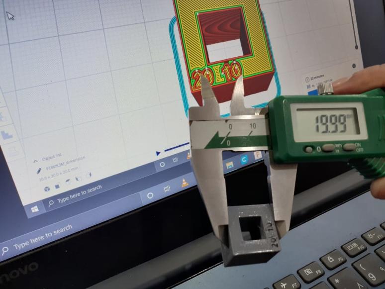
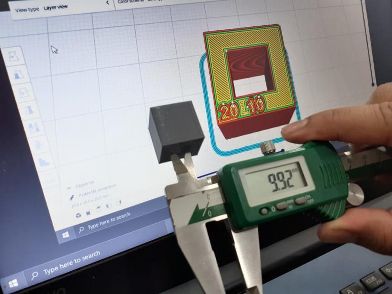
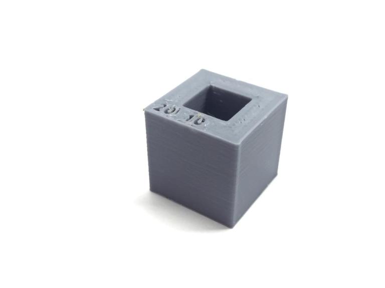
Dimensions
Anisotropy
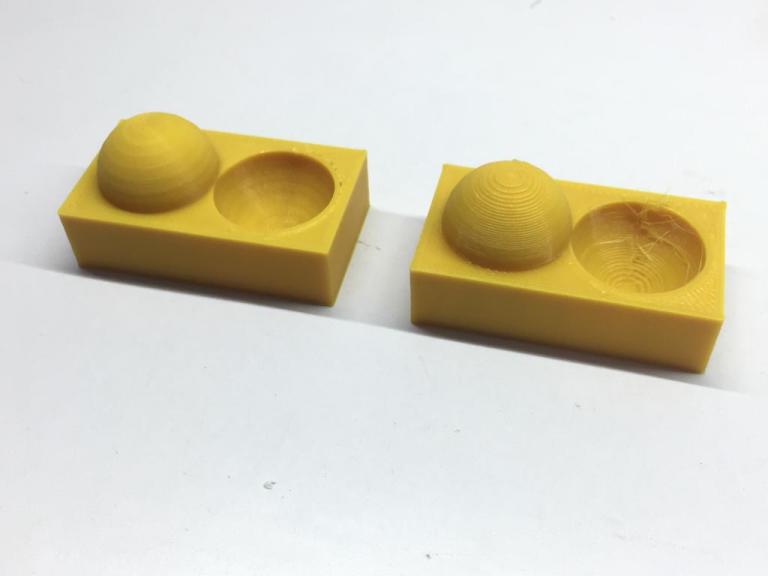
Surface Finish
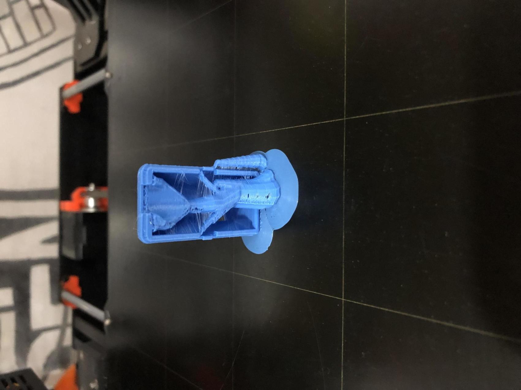
OK Now we are done, here's a photo for you.
Individual Assignment
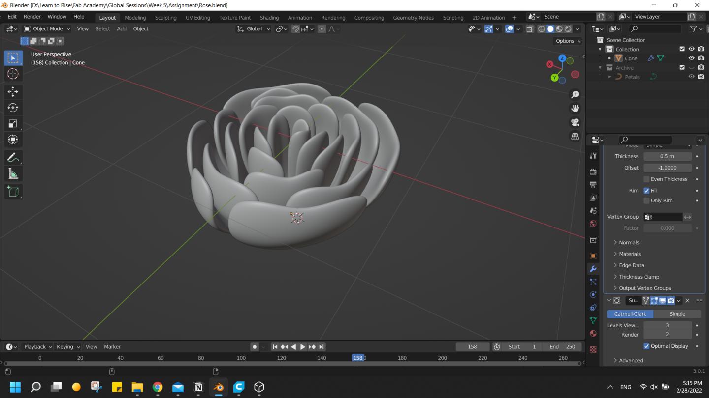
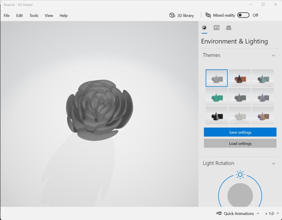
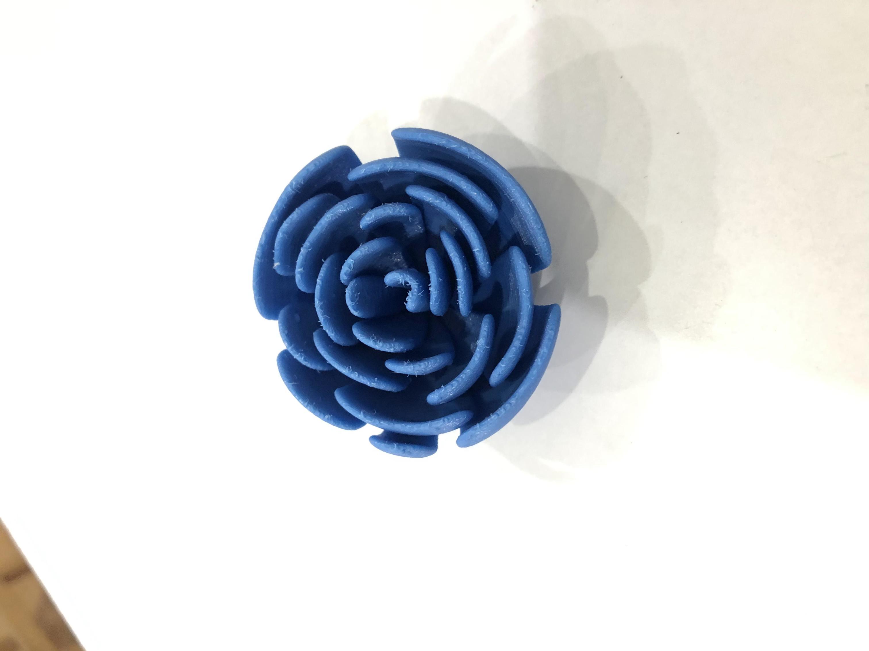
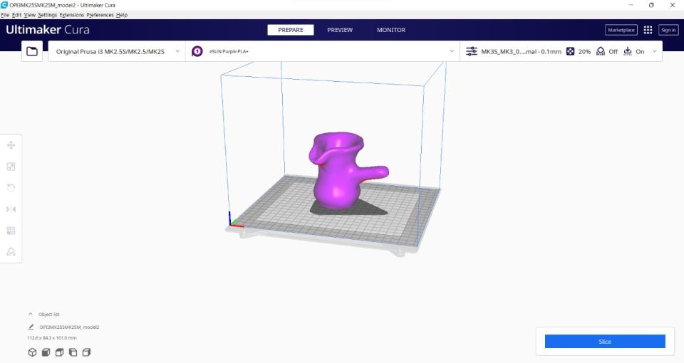
I should design a model that could not be made subtractively and 3D print it, so I decided to design a rose head I wanted to do it long time ago.
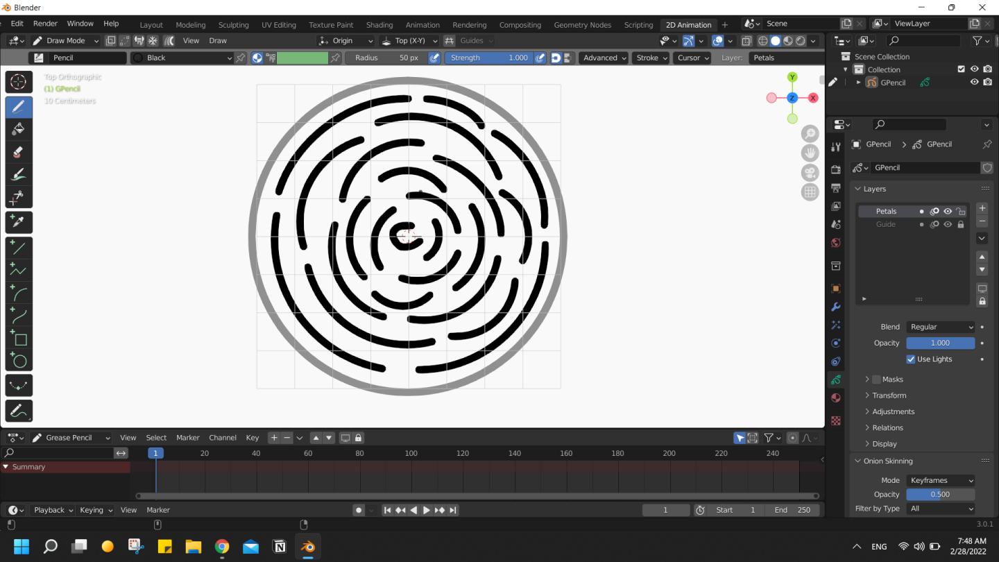
Practice

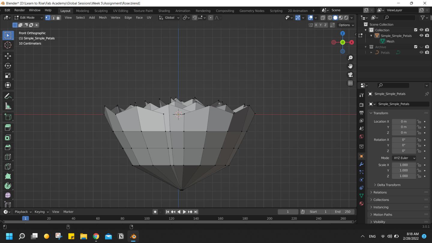
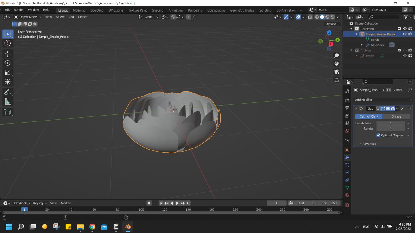
Design
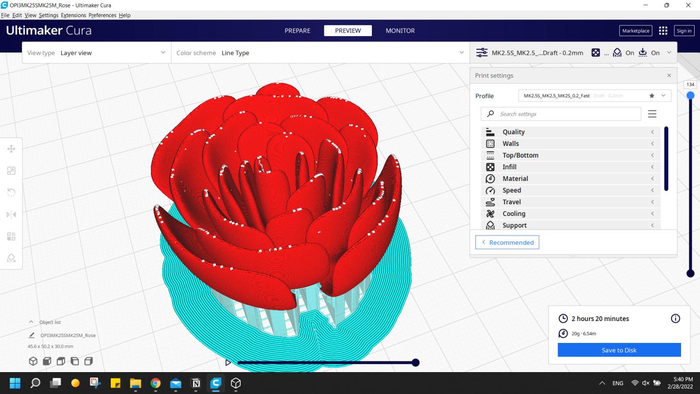
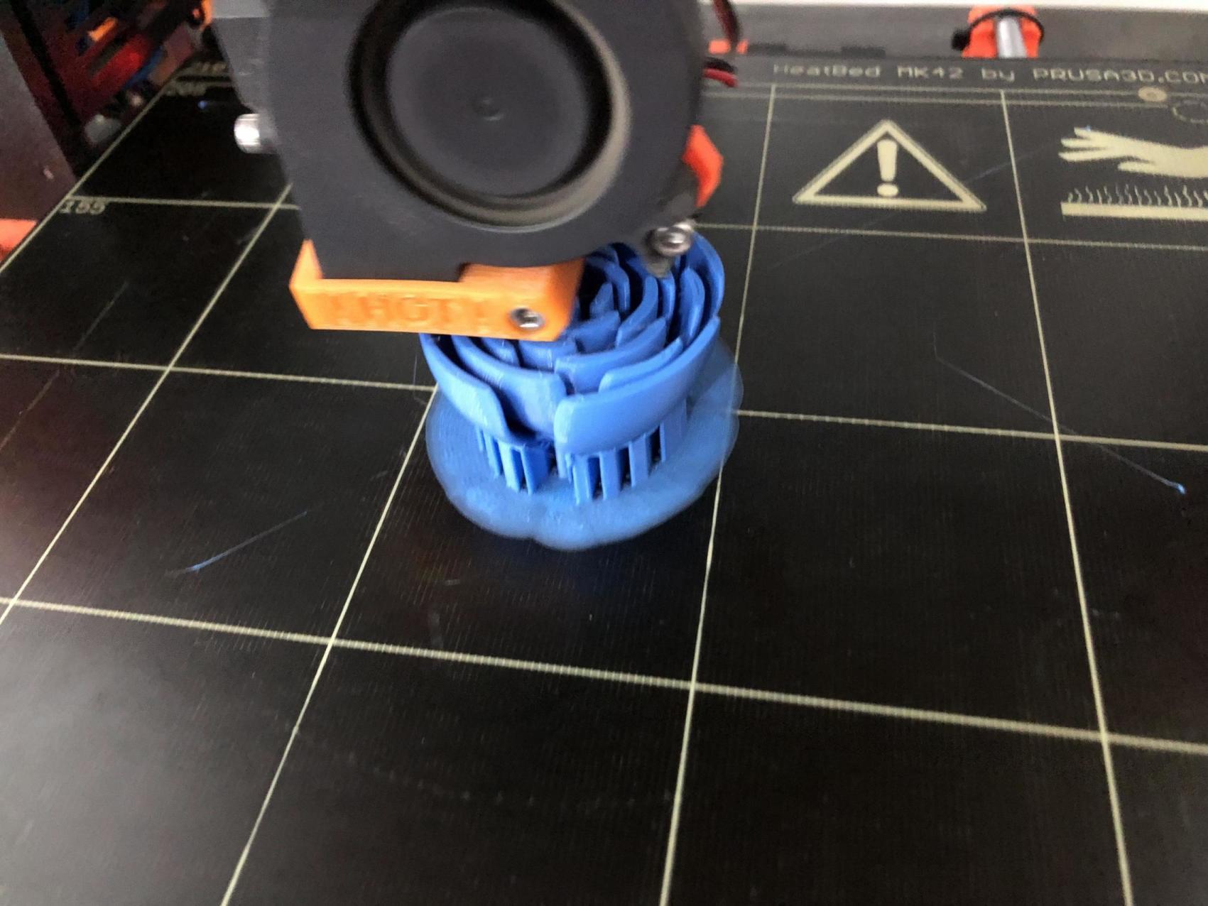
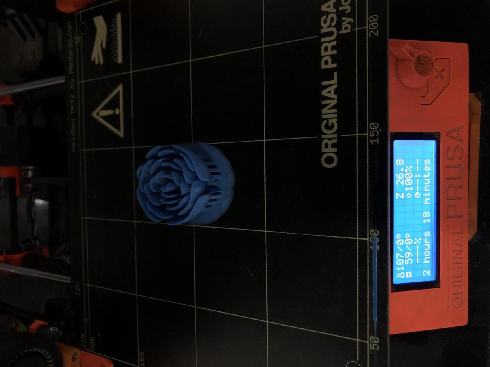
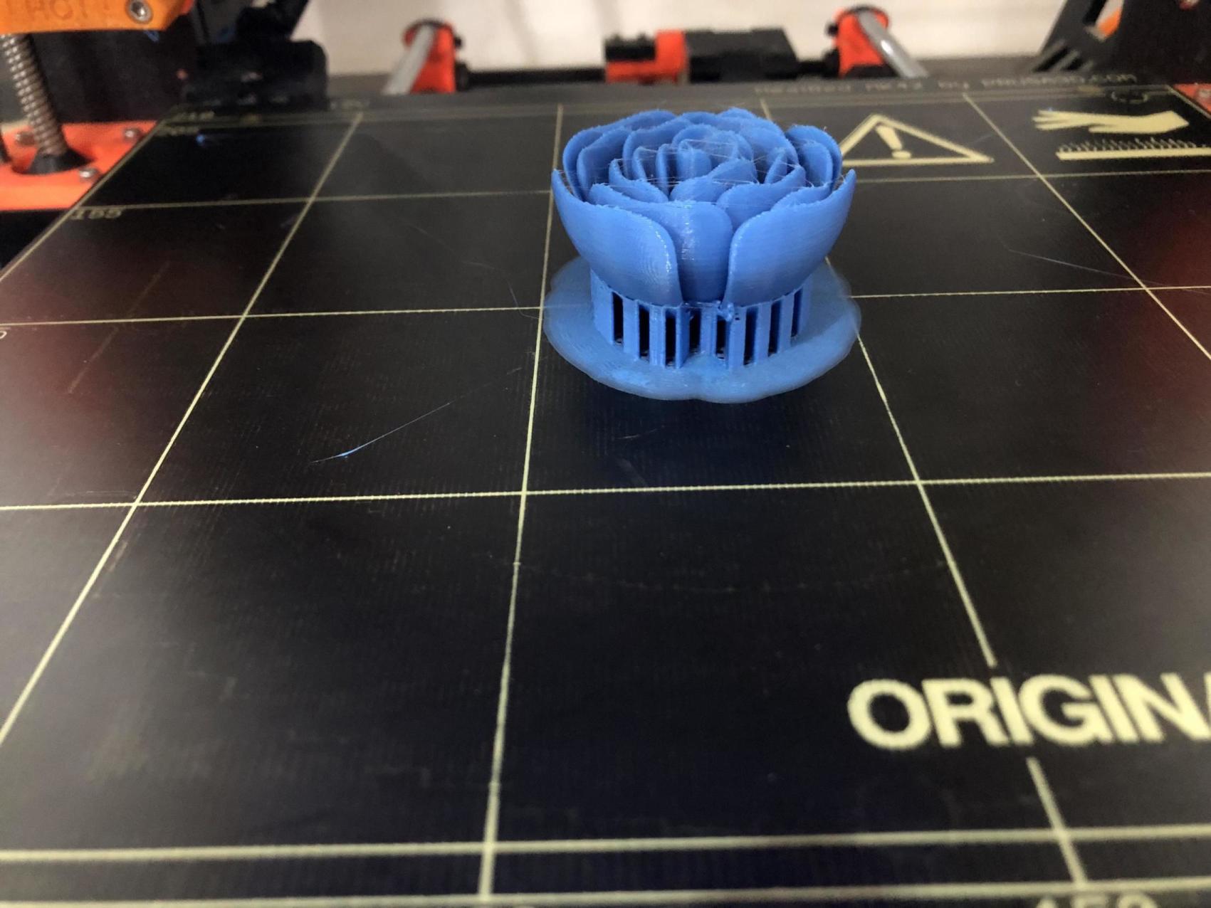
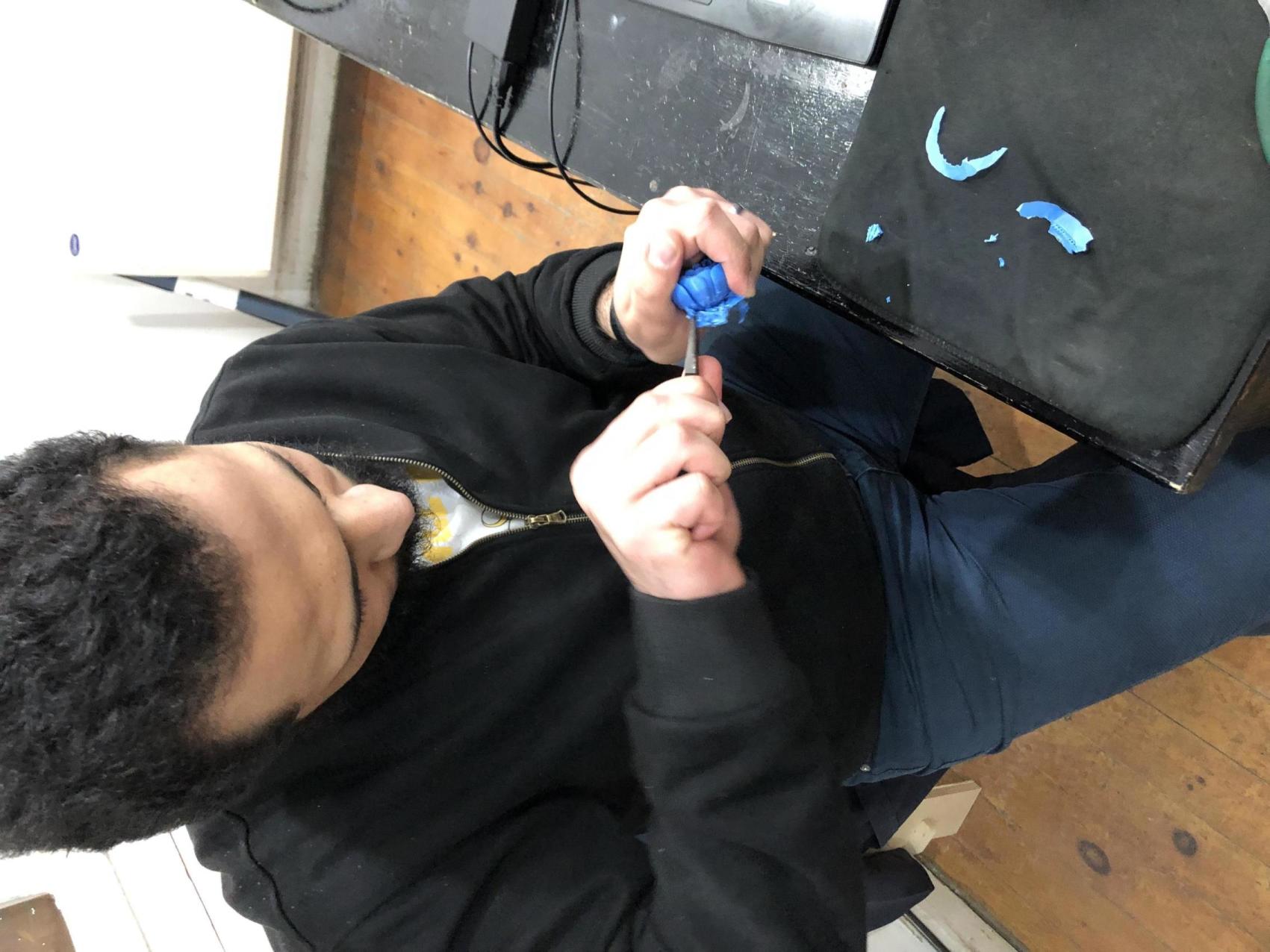
3D Printing
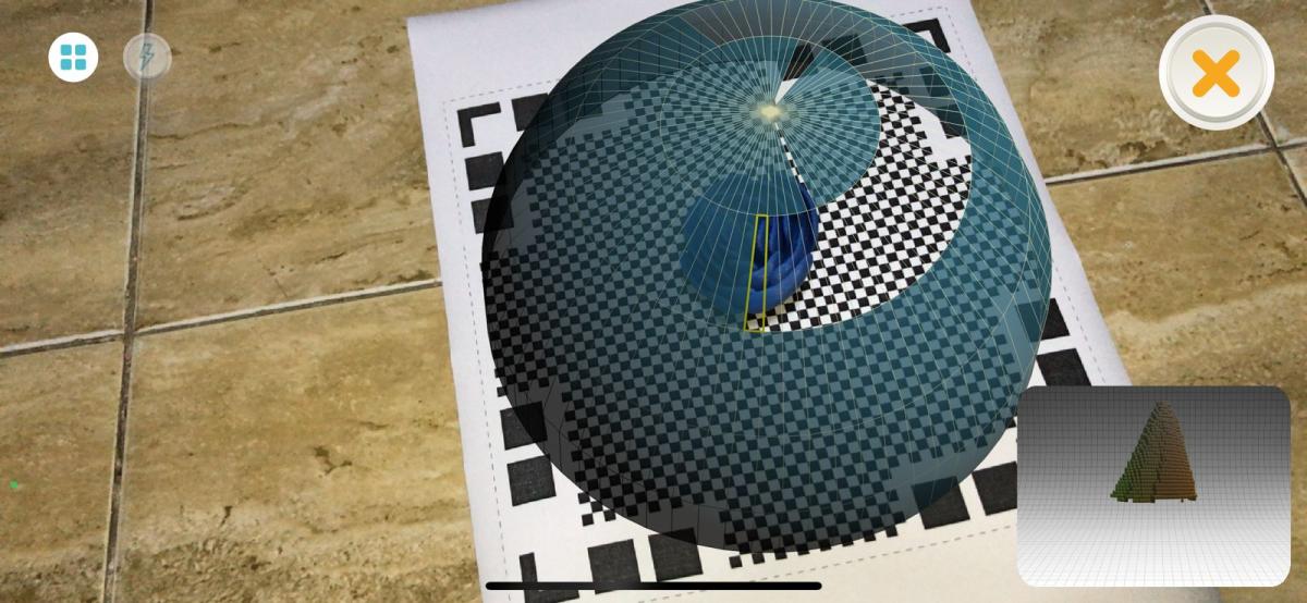
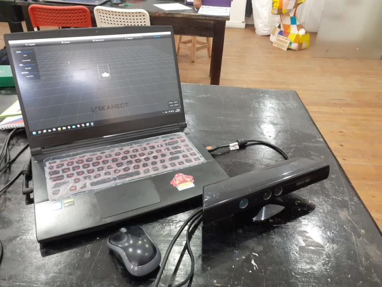
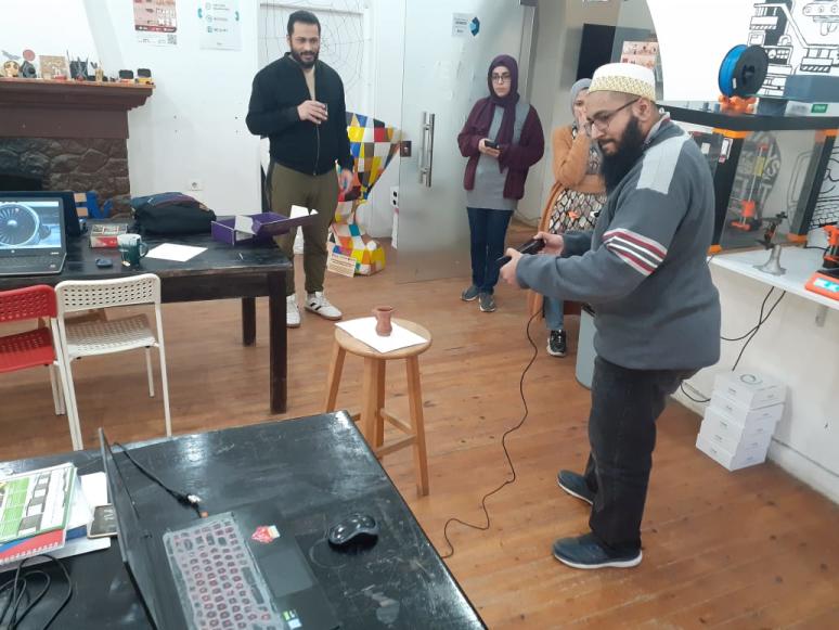
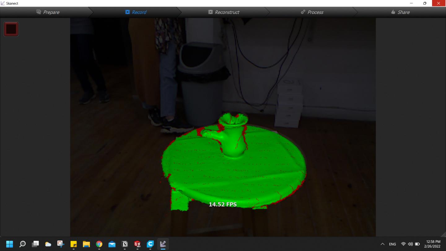
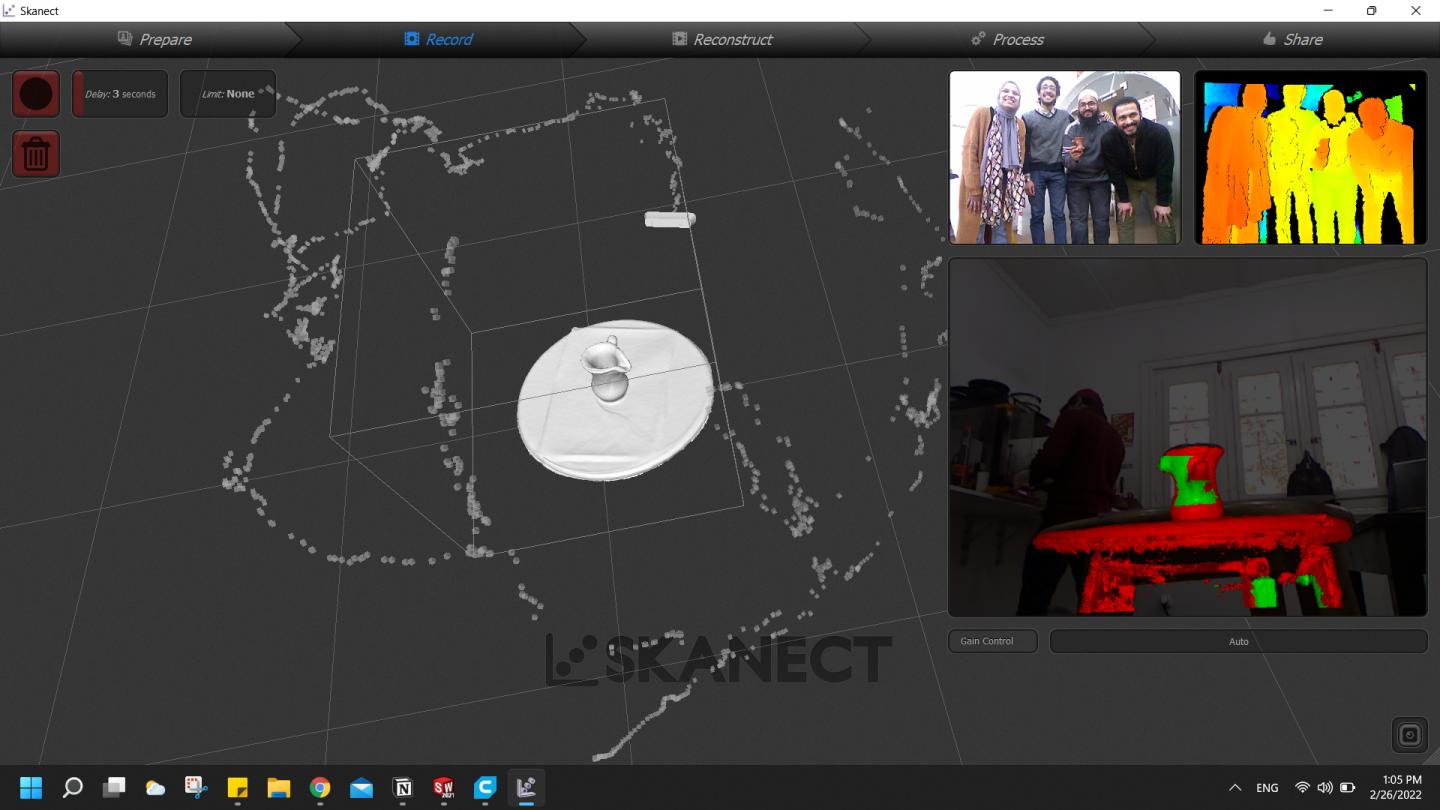
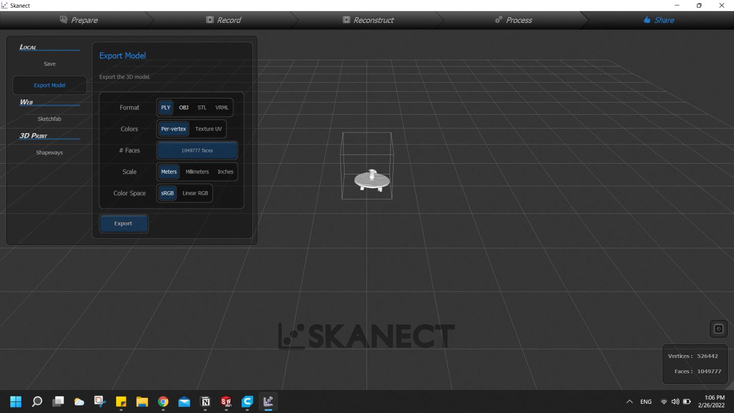
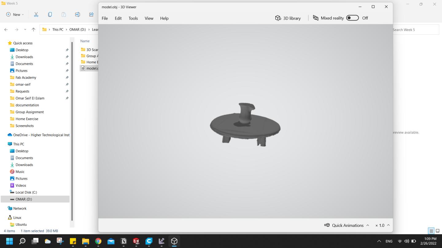
3D Scanning
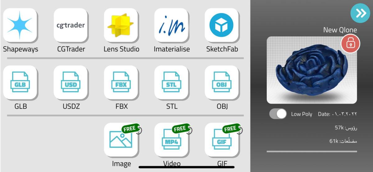
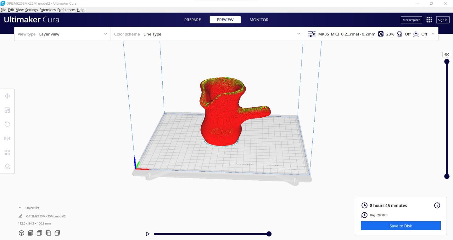
We didn't print it due to it's high weight and also printing time, I was focusing on giving the rose the best I can.