Assignment requirements:
Group Assignment
- Characterize the design rules for your PCB production process: document feeds, speeds, plunge rate, depth of cut (traces and outline) and tooling.
- Document your work (individually or in group)
Individual Assignment
- Make an in-circuit programmer by milling and stuffing the PCB, test it, then optionally try other PCB fabrication processes.
Learning outcomes:
- Described the process of milling, stuffing, debugging and programming.
- Demonstrate correct workflows and identify areas for improvement if required.
Assessment criteria
- linked to the group assignment page
- Documented how you made (mill, stuff, solder) the board.
- Documented that your board is functional.
- Explained any problems and how you fixed them.
- Included a 'hero shot' of your board.
Group Assignment
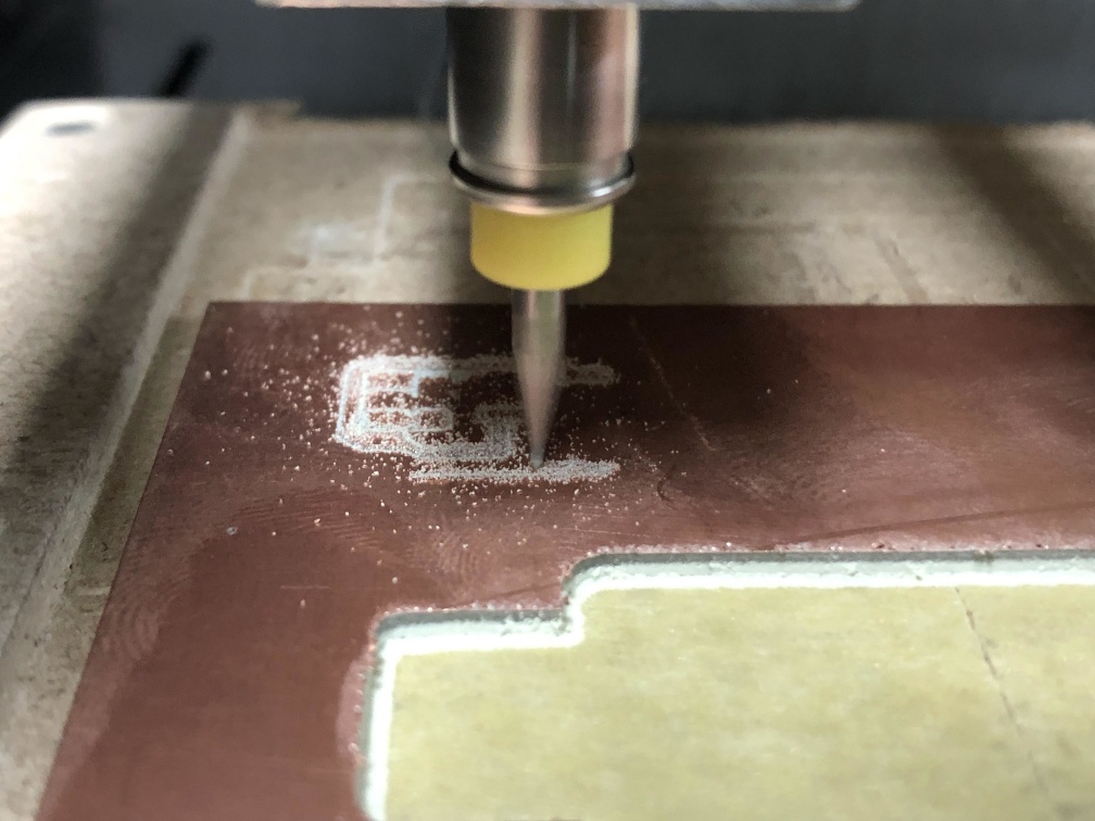
In this week we want to characterize our milling machine, we have 2 machines Modela MDX-20 and another small router machine.
So we divided to 2 groups to work on both machines and I worked on Modela team.
Preparing
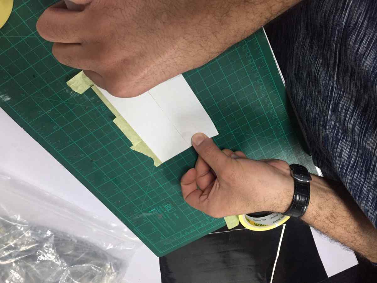
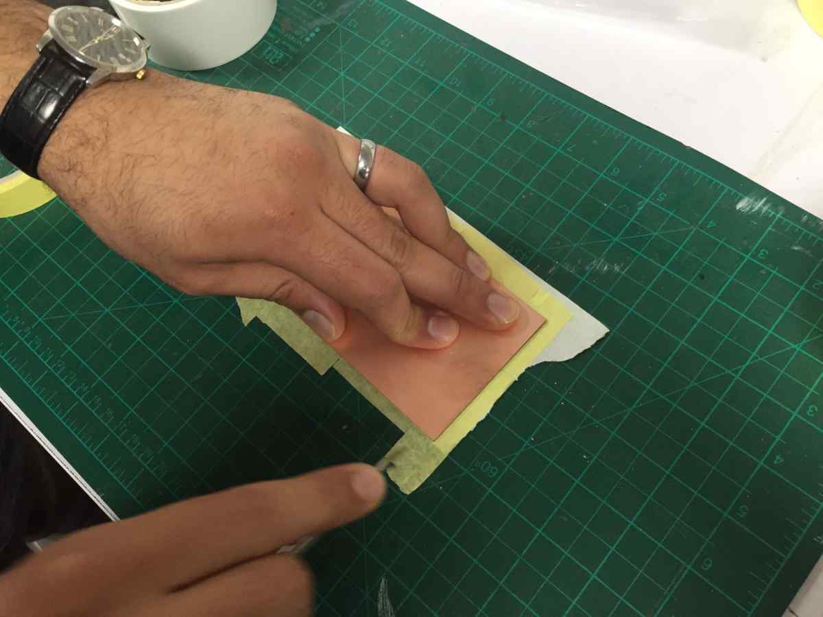
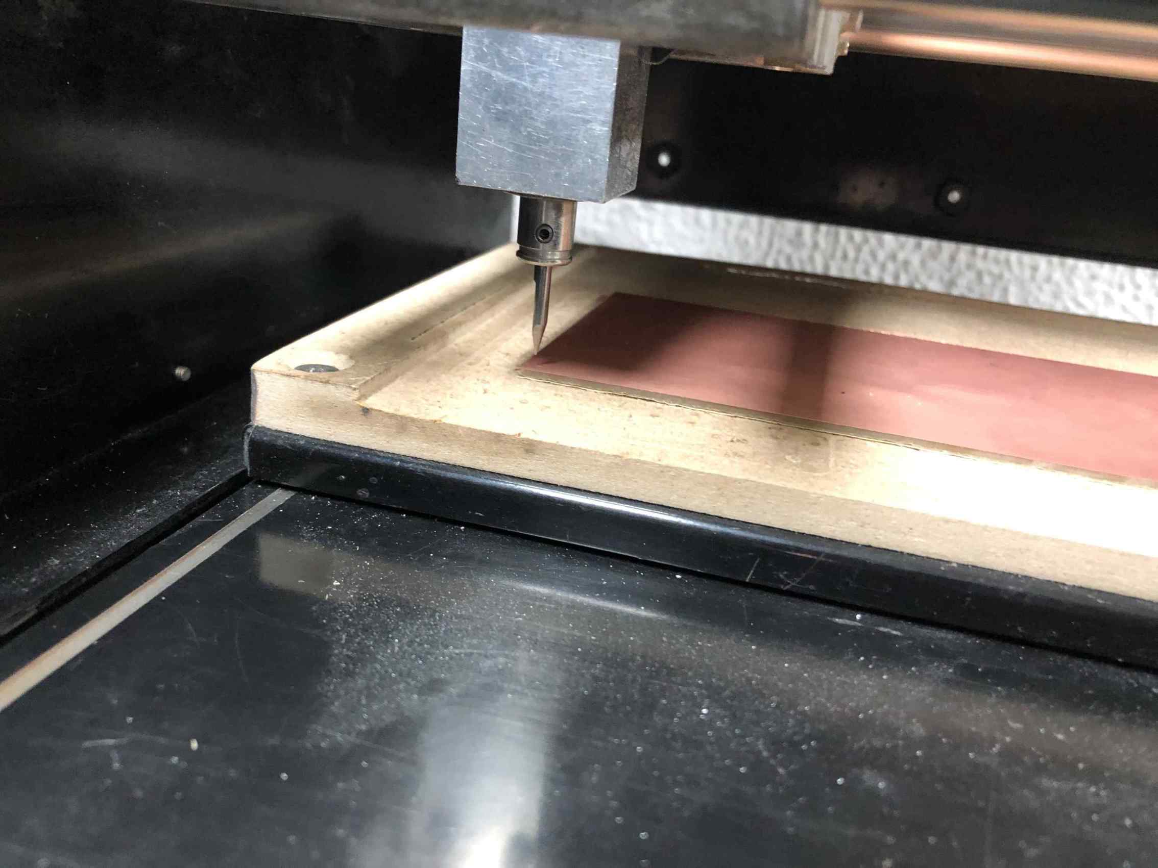
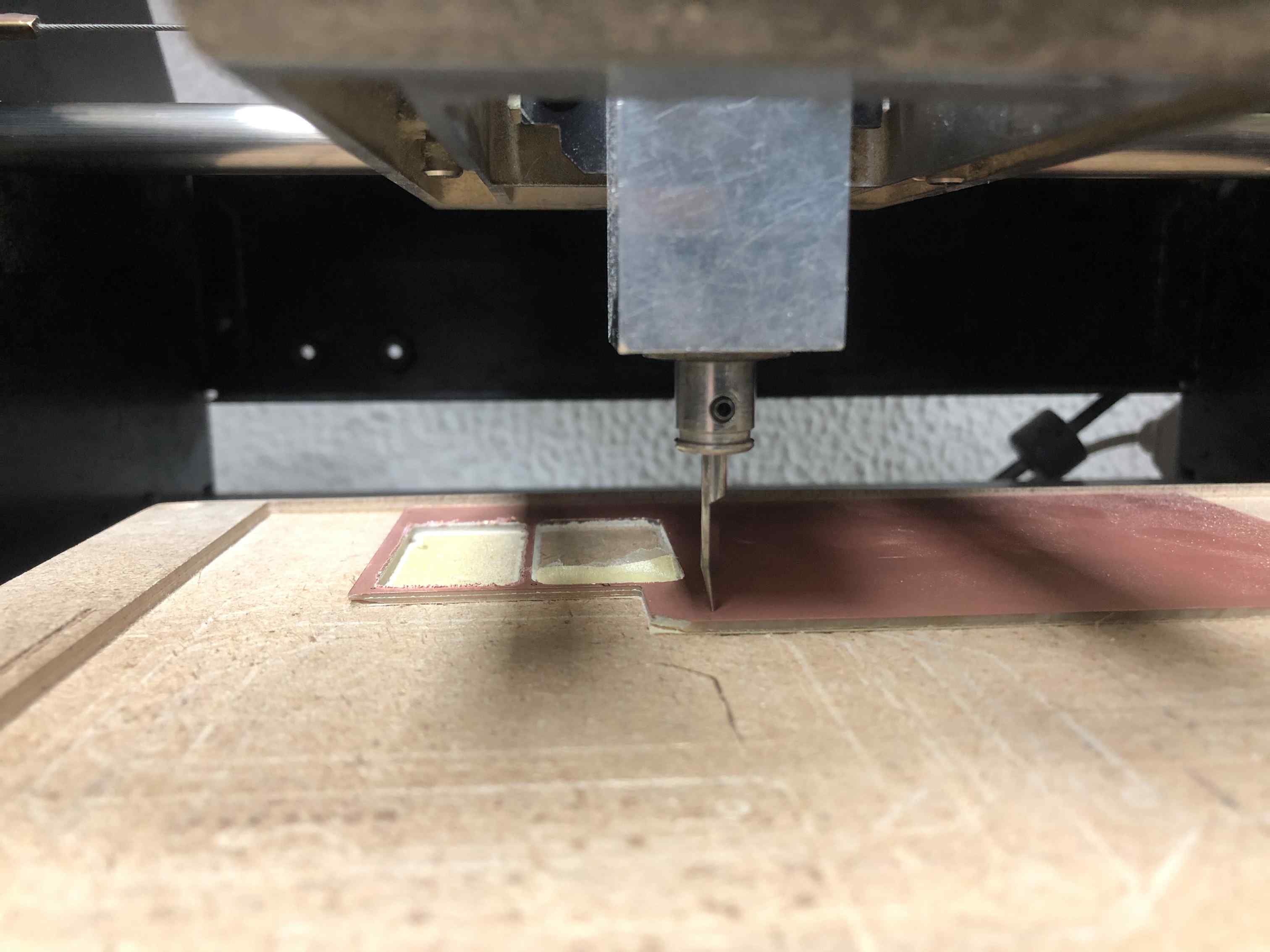
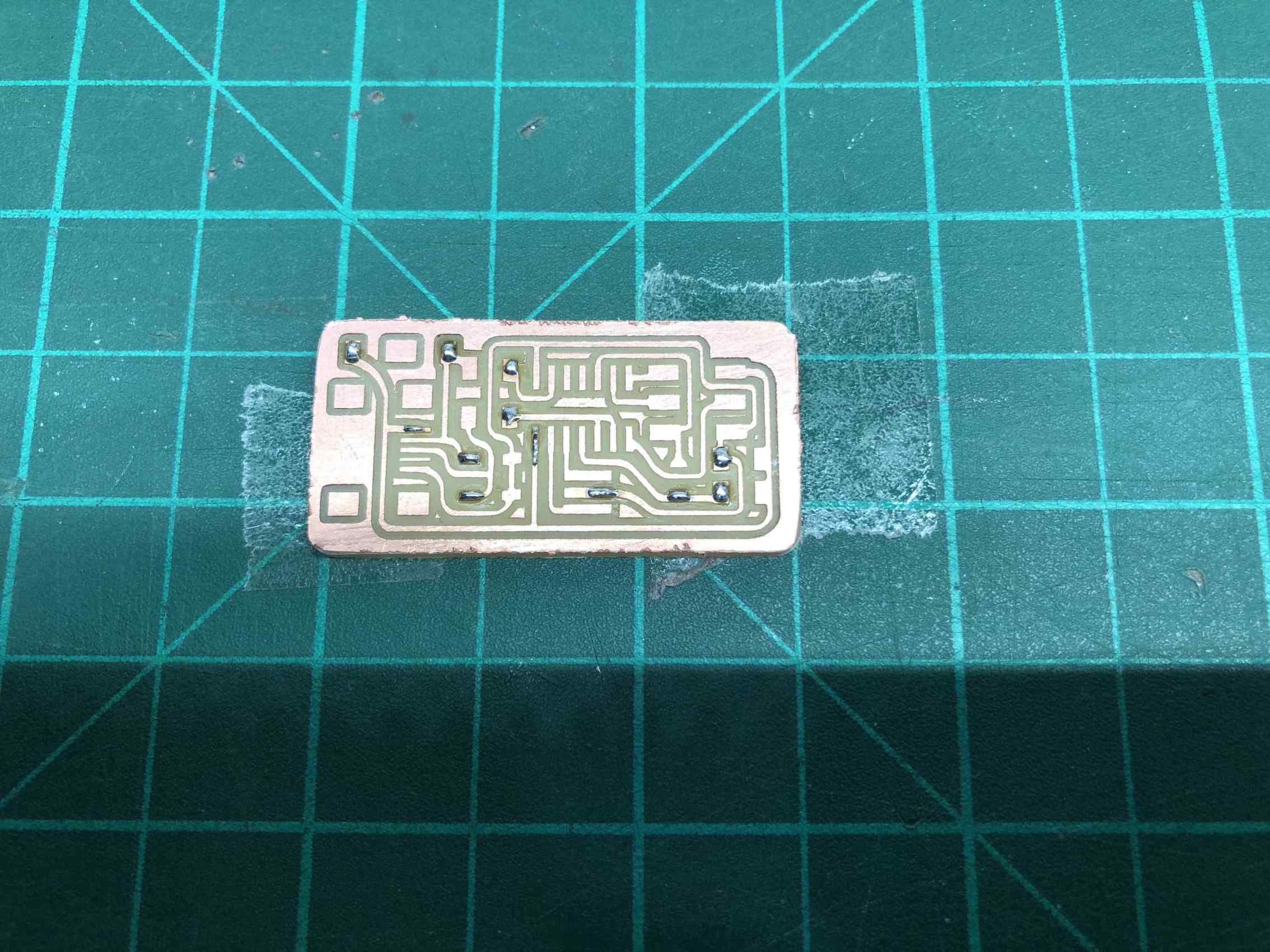
We started by preparing our PCB with a layer of tape then a layer of double face.
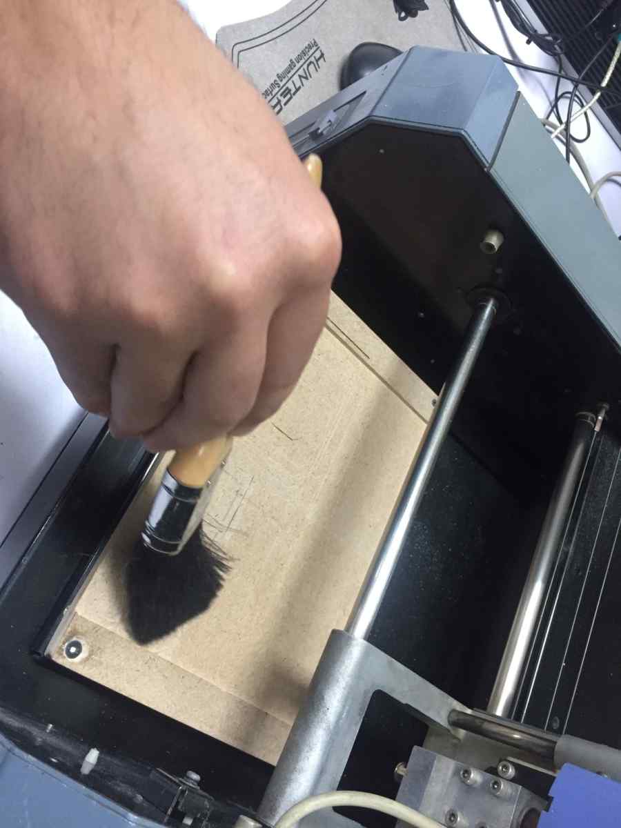
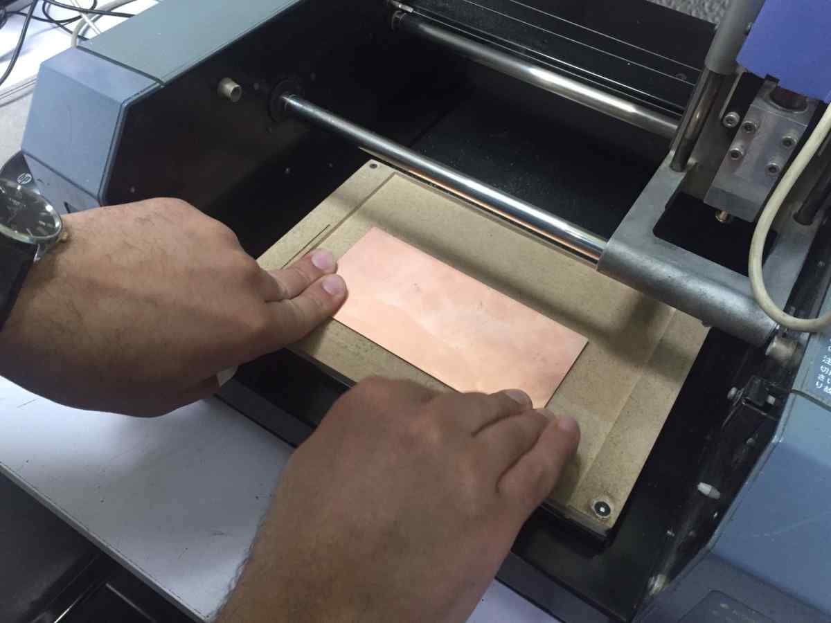
Clean the machine and stick PCB to it.
Milling
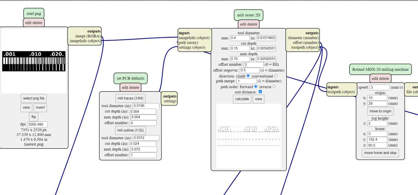
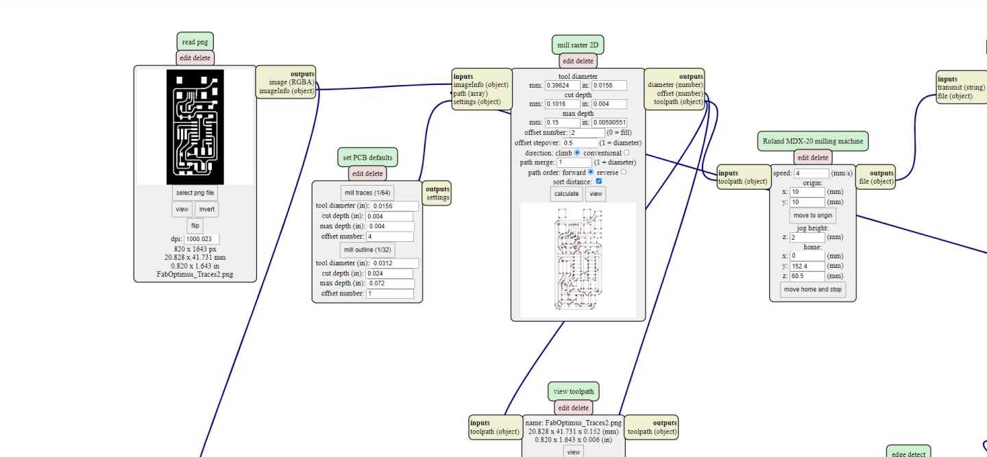
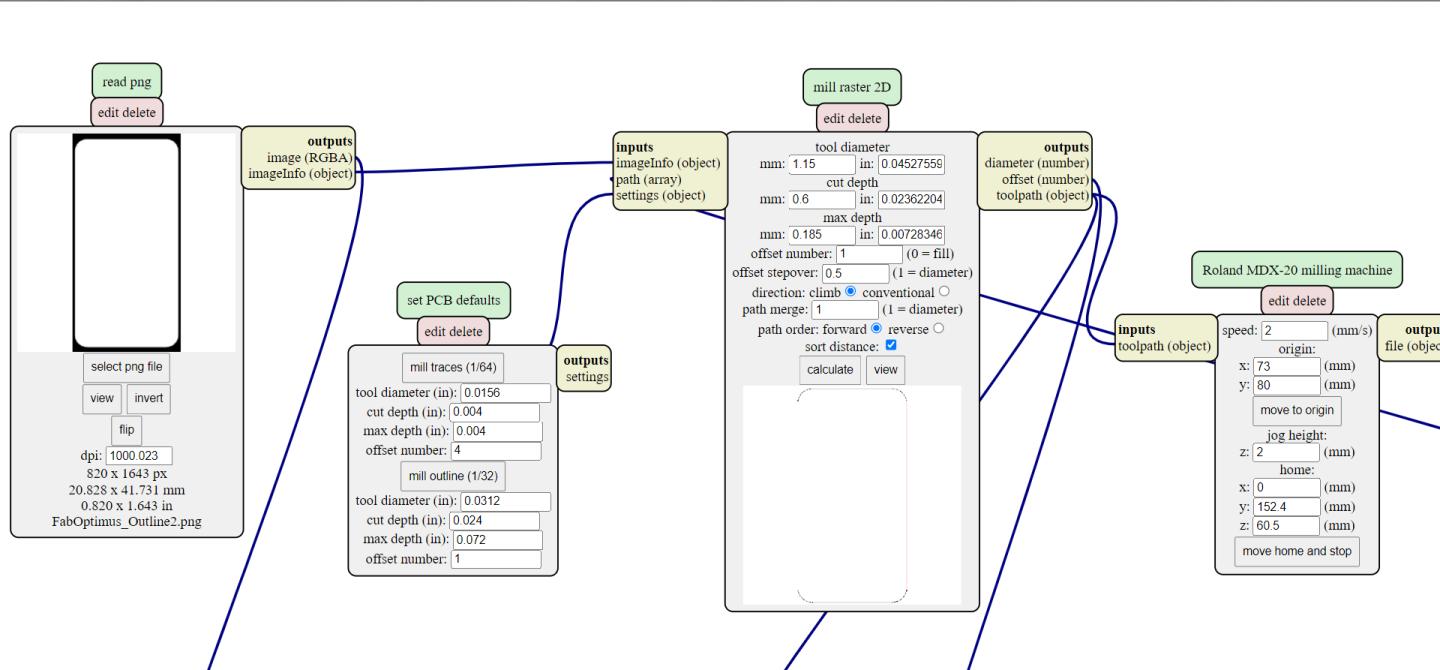
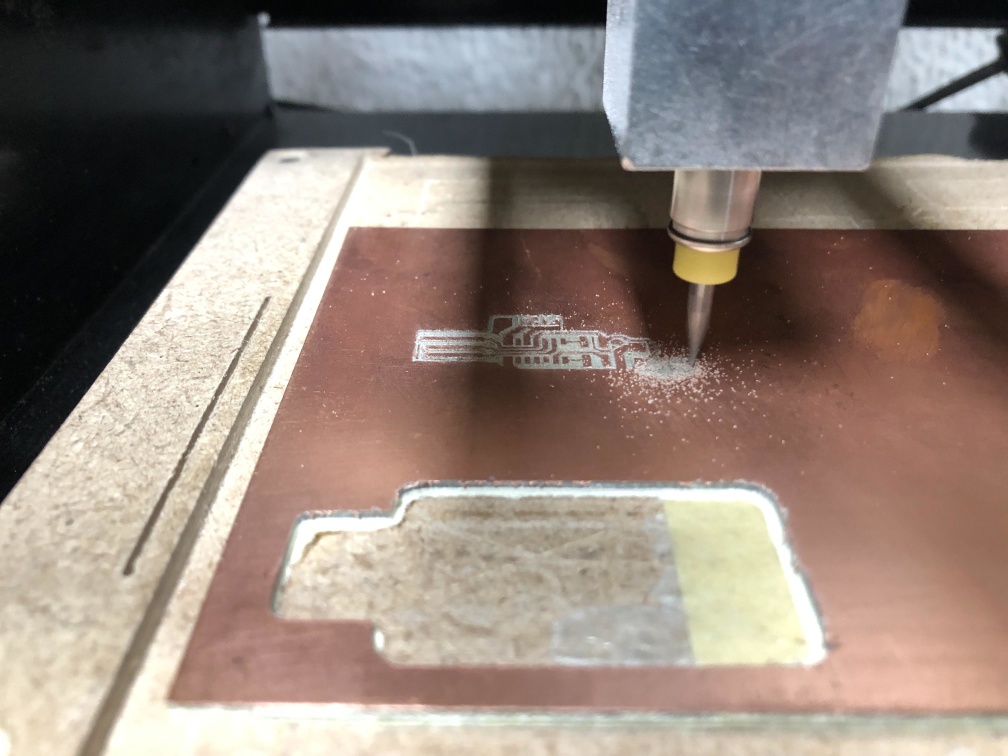
Open mods right click anywere on the white board > Programs > open server programs > Roland > mill > MDX-20 > PCB png.
Select the png then edit the endmill parameters, then calculate, Set x,y from mods and z manually from the machine.
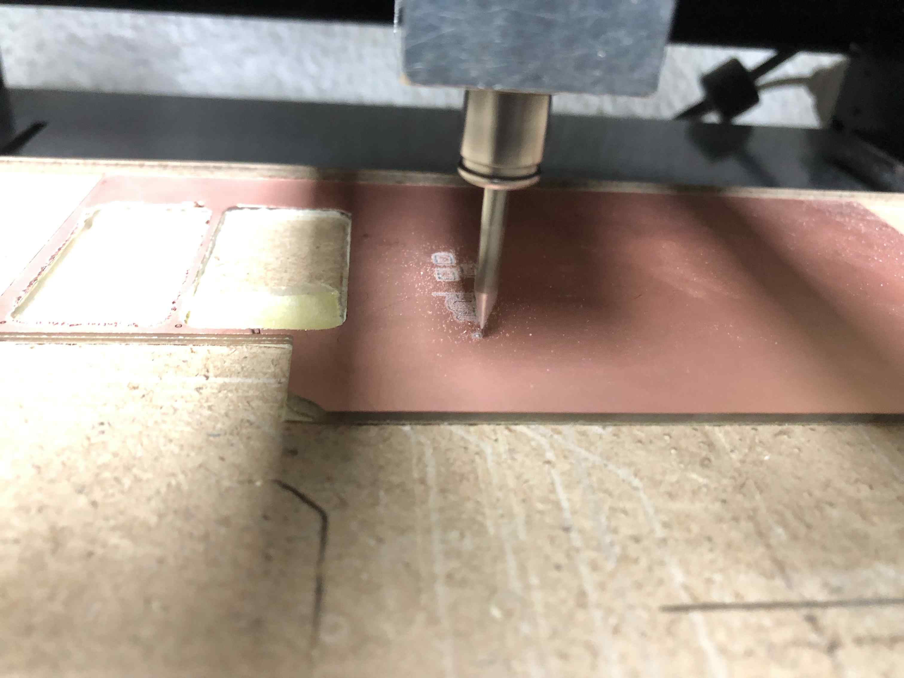
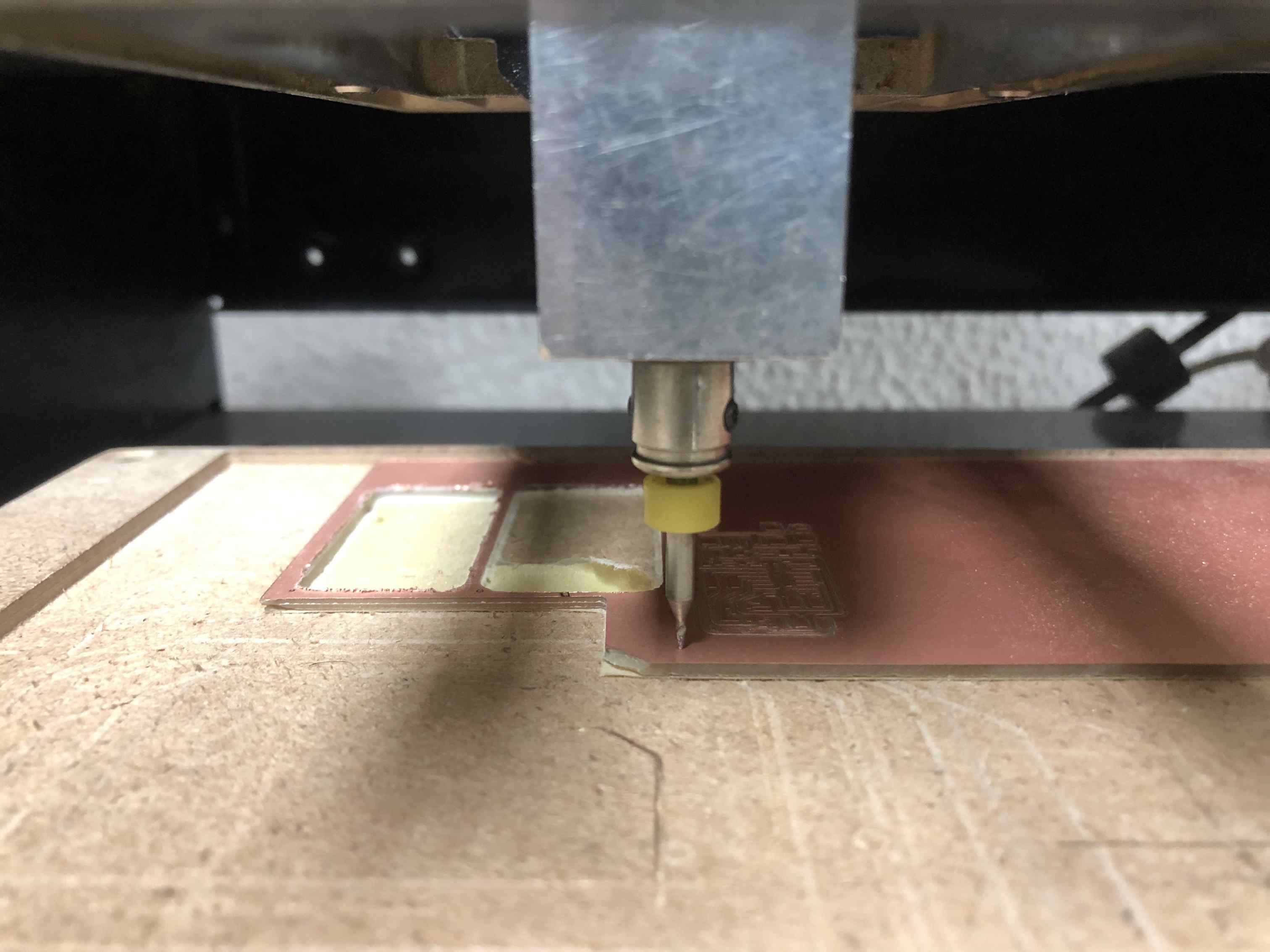
Send, watch and enjoy.
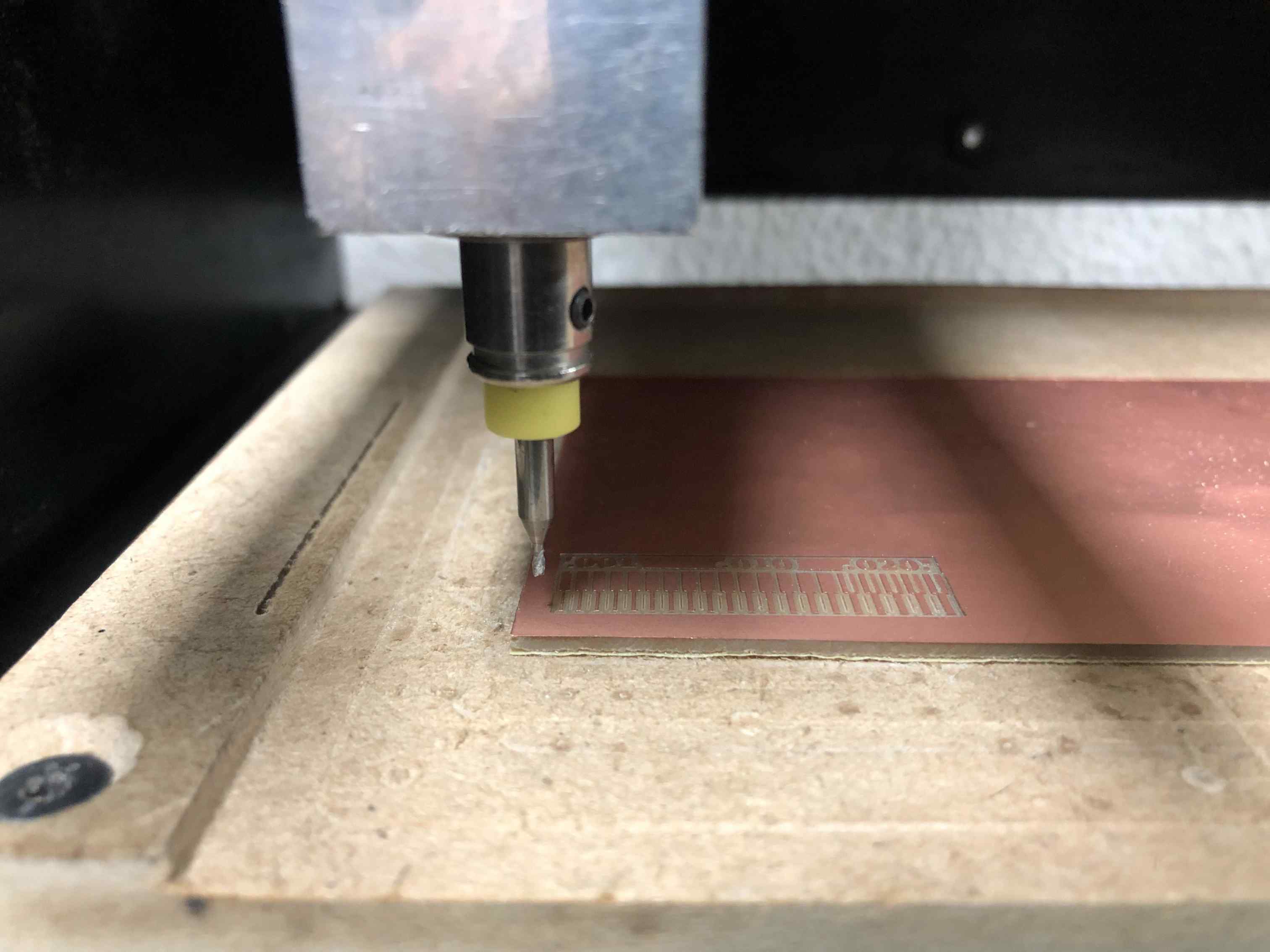
Remove the V-bit and put the outline endmill and set Z manually again.
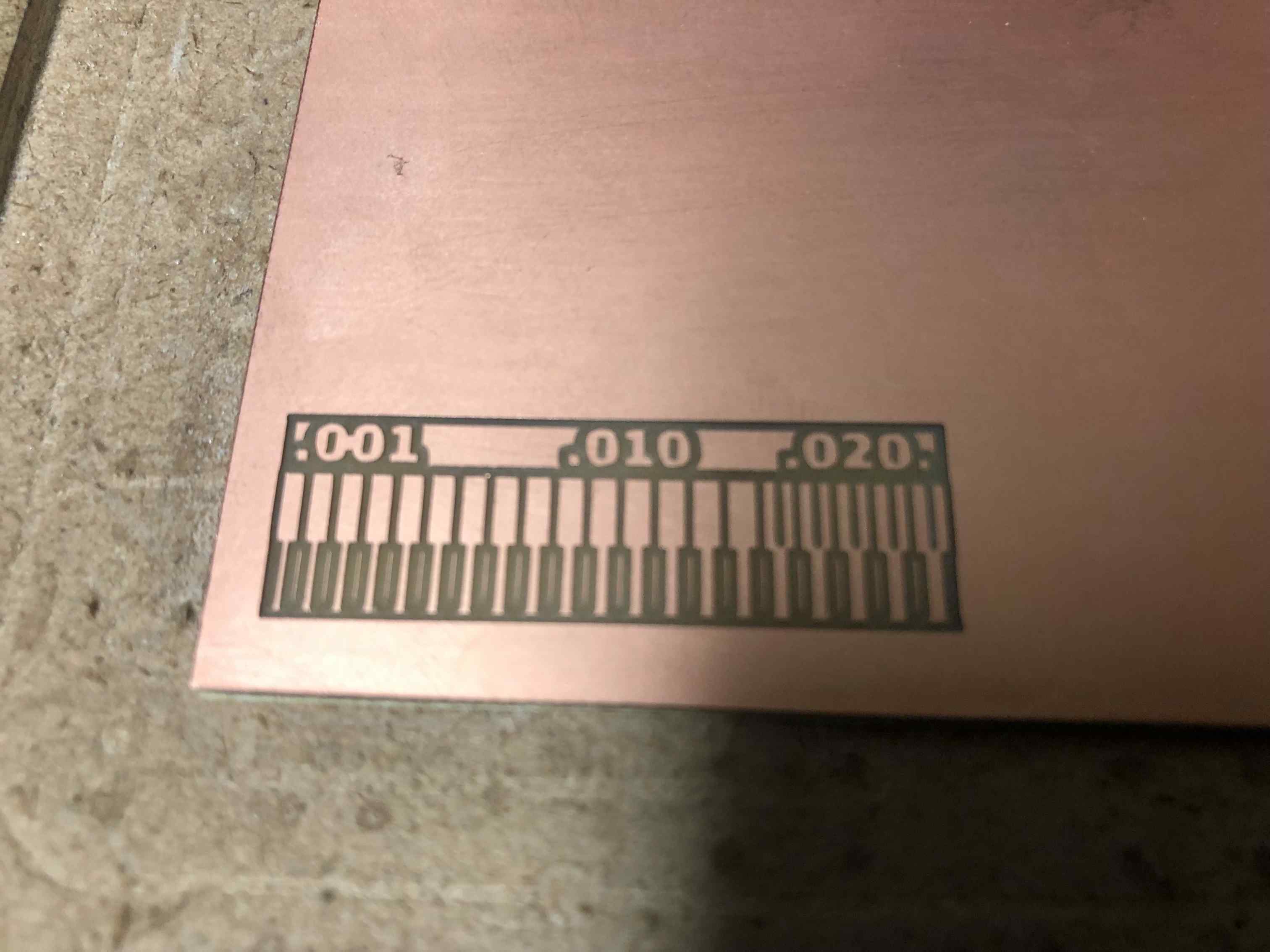
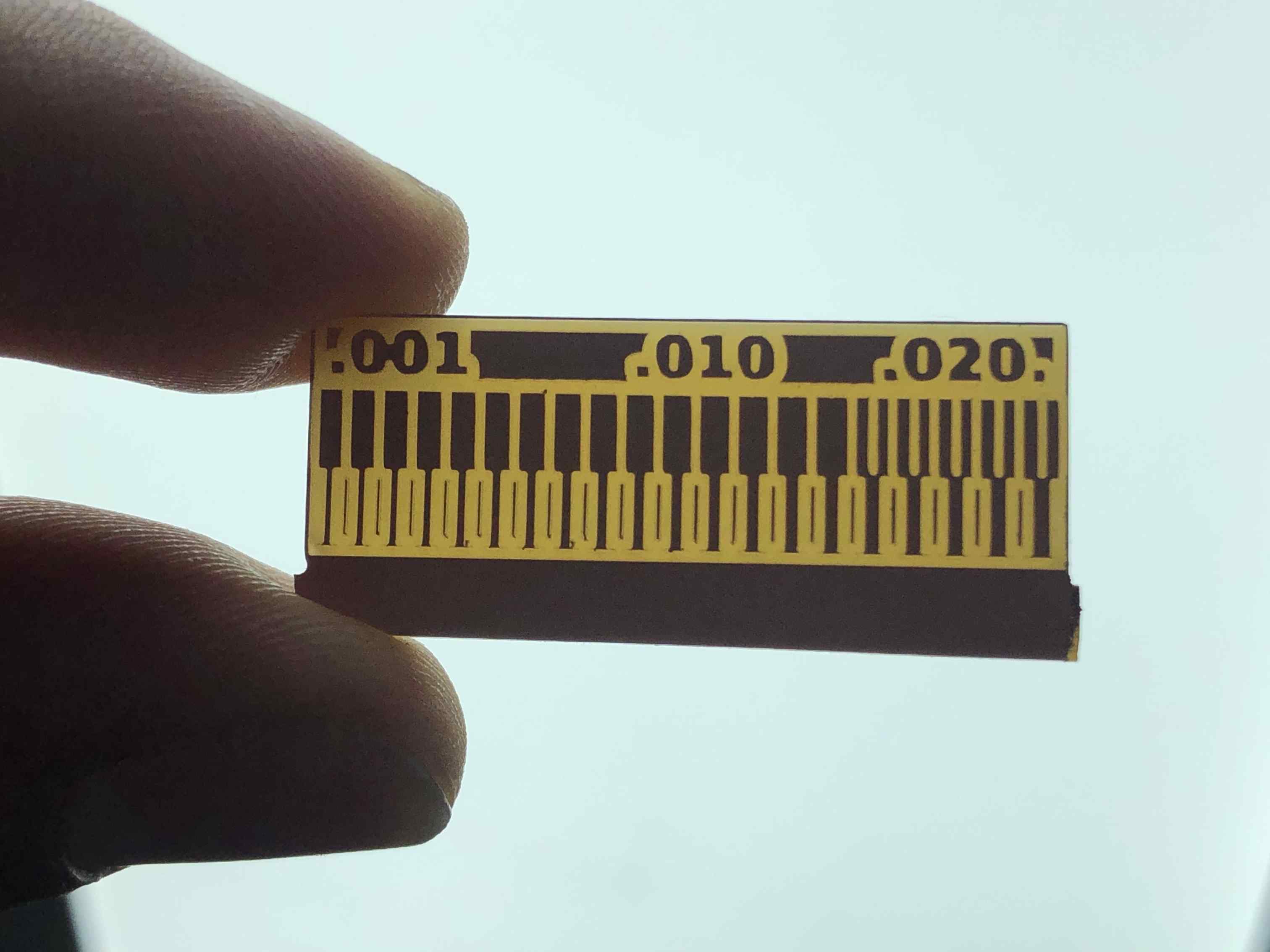
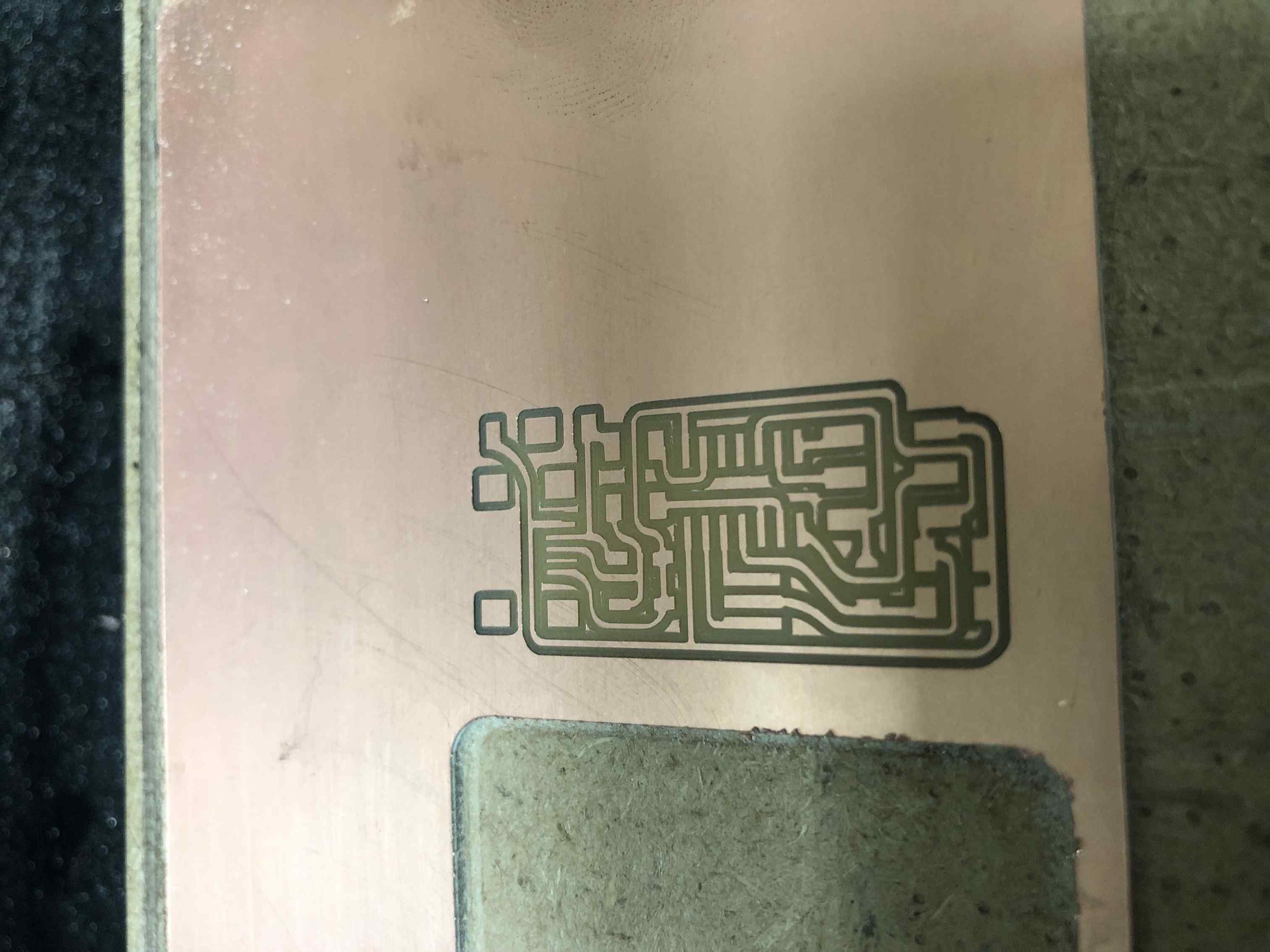
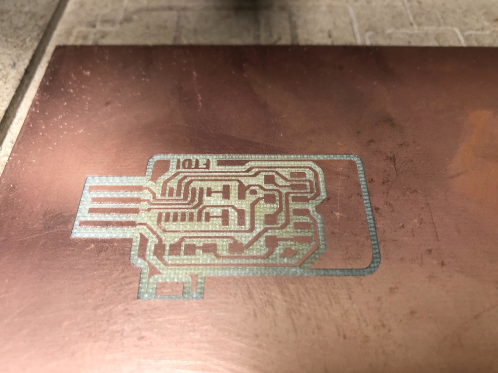
Repeat mods steps but with outline png, when we did that the bottom line didn't appear in calculation because out outline endmill is 1.15mm,
so we moved on and as the board was in the PCB corner we manually removed it, that's why you can see the bottom corner of our board looks weird
but we were happy with the result from our Modela machine.
FabISP
First we decided which programmer we will manufacture and with recommendation from our instructor to make an ISP programmer.
I went to Ali FabOptimus programmer and started working on it,
Milling
Downloaded (R_pullup=1K+0.5K) traces and outline png.
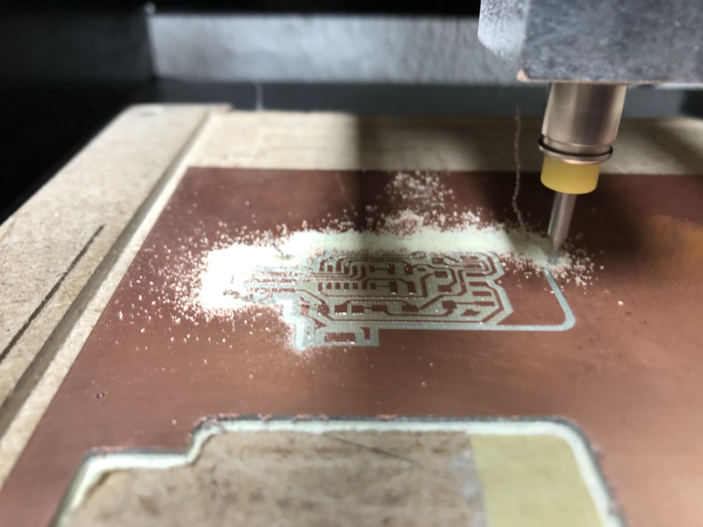
Do the Same steps as group assignment with mods to fabricate the board.
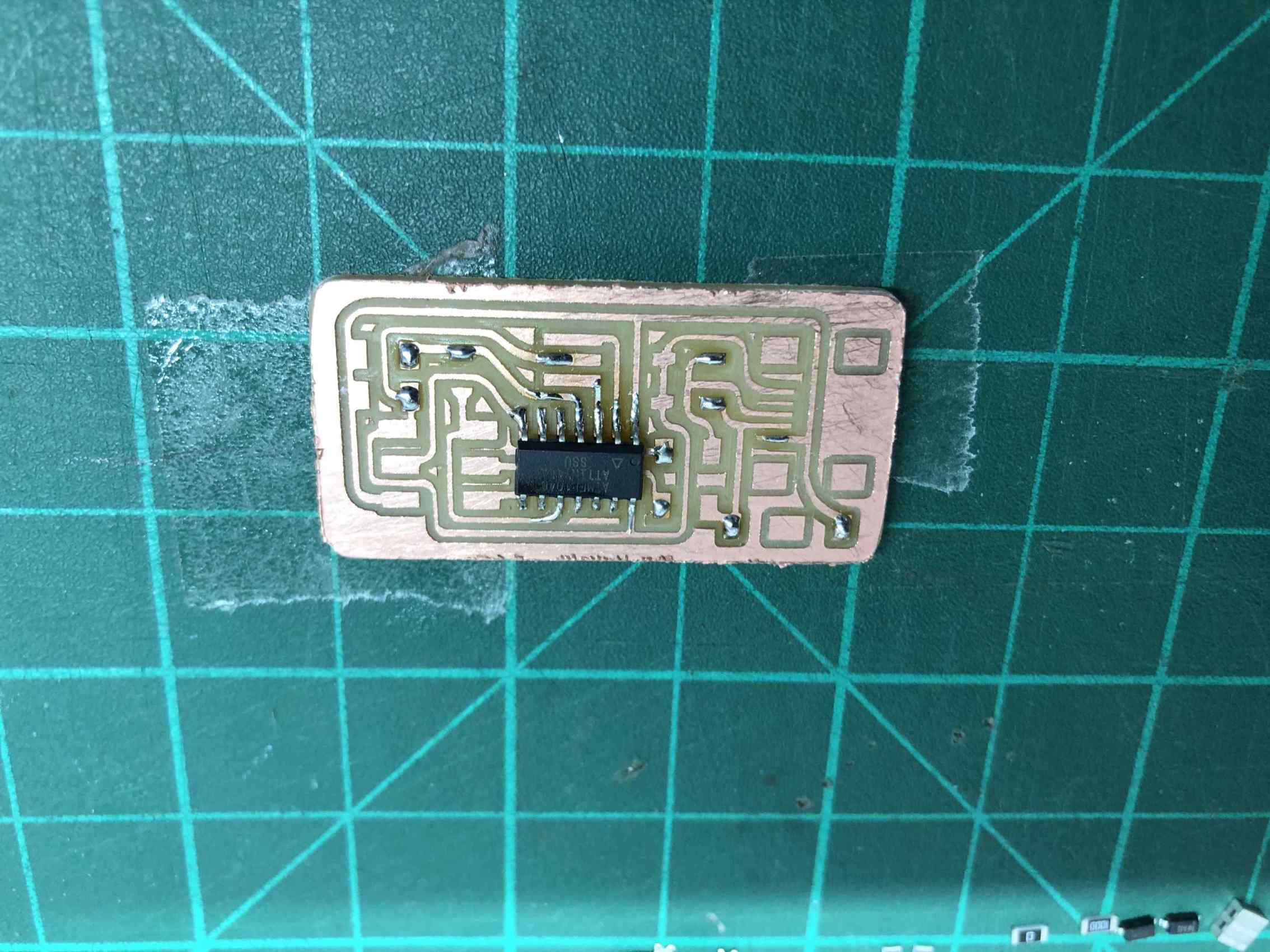
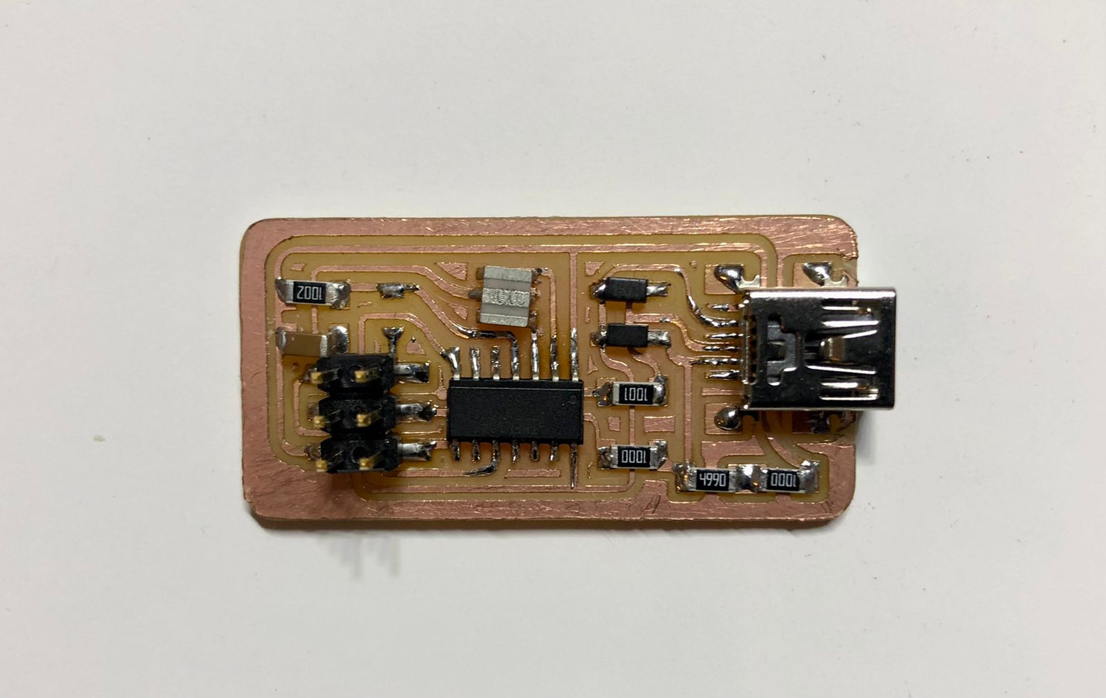
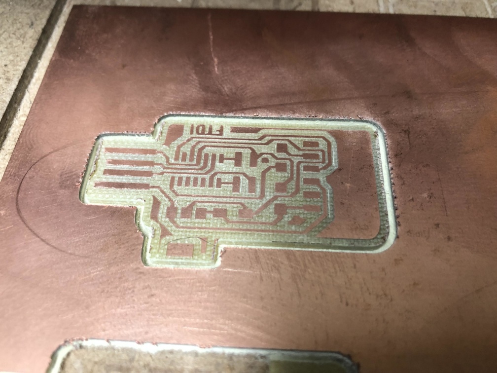
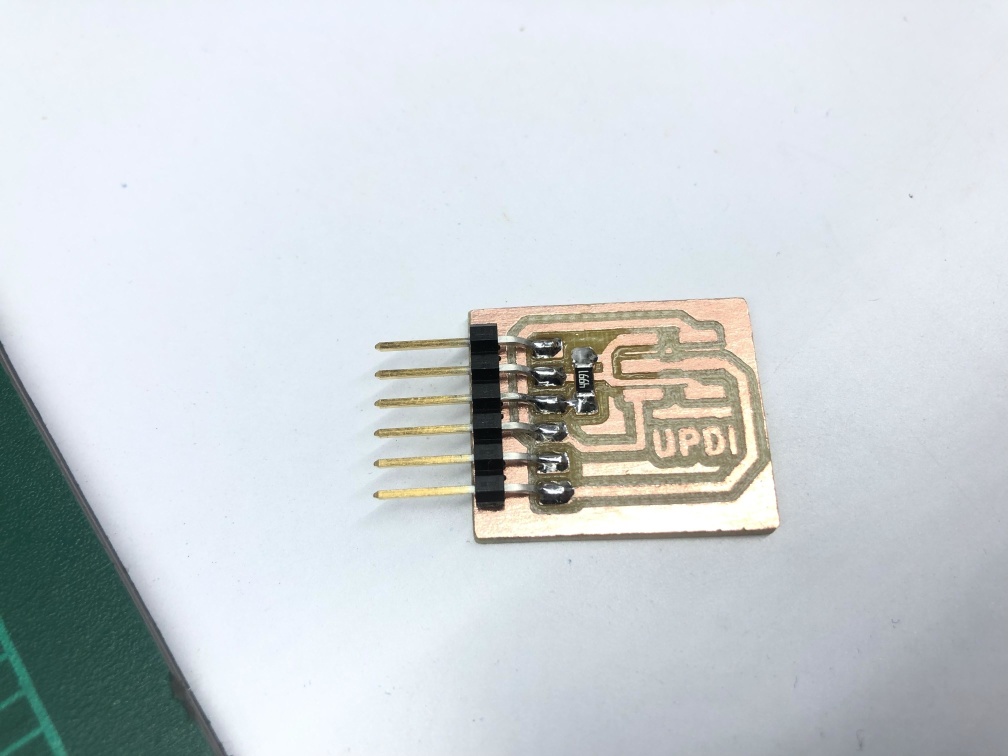
Start tracing, after finishing start with outline, I made 2 boards because I broke my first board while using a bad iron that has very hight temp. which poped up the trace.
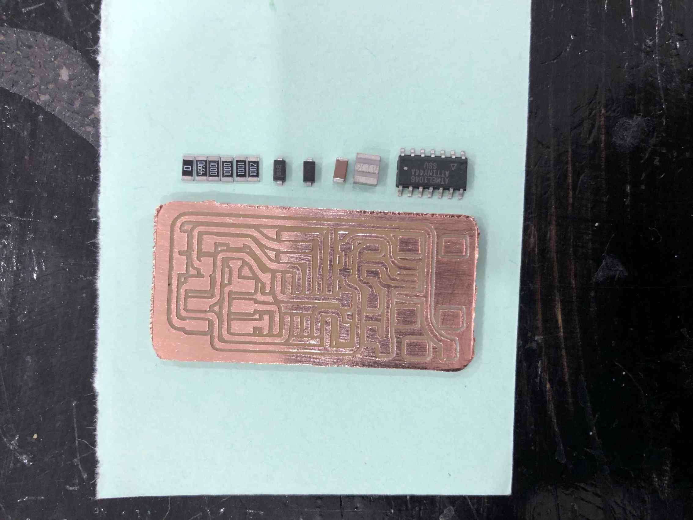
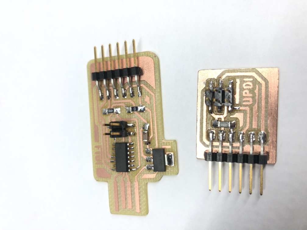
The picture on the right is my seconed board and I put it because it came out much better the first one.
Outline, then clean PCB.
Soldering
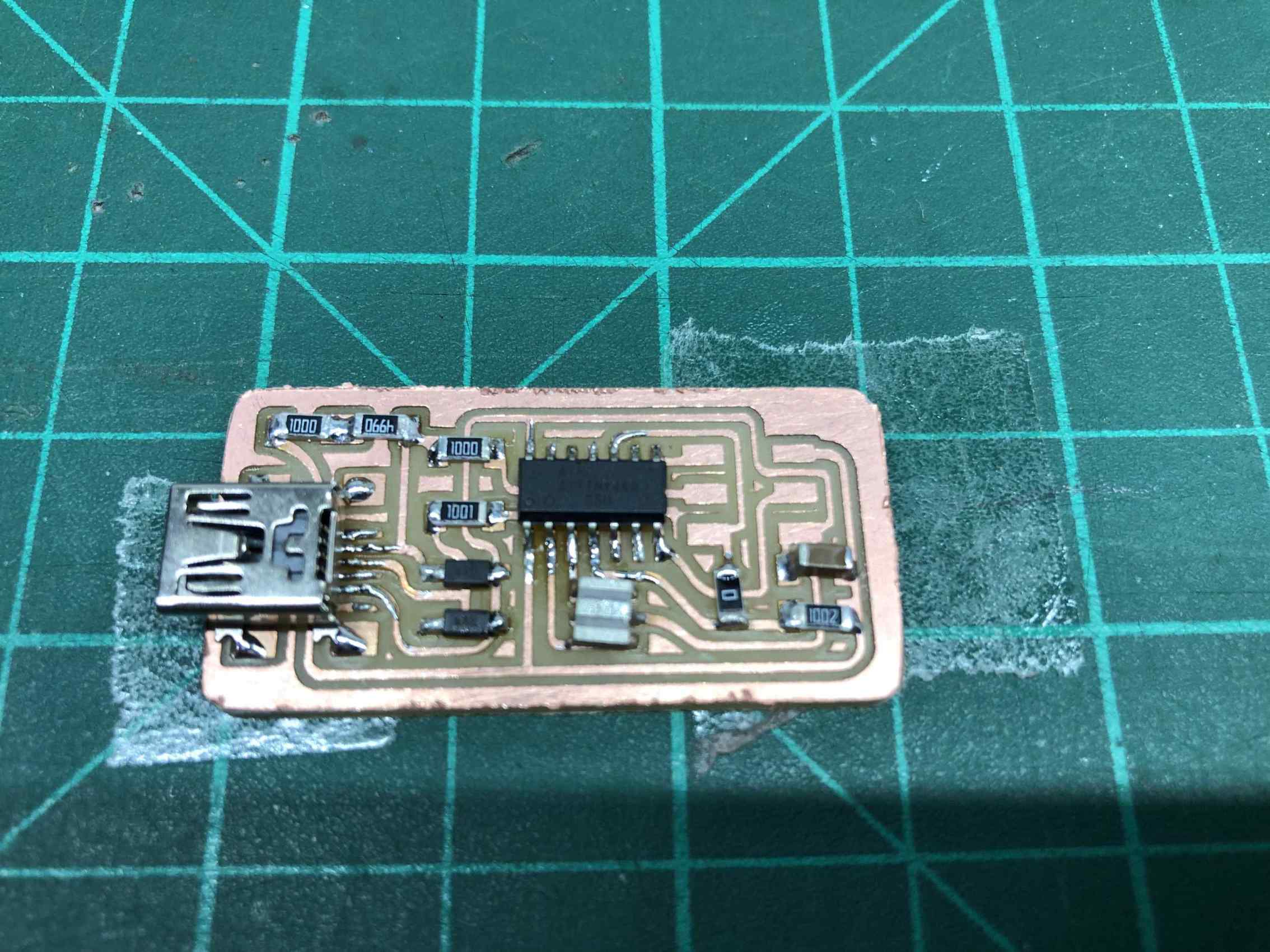
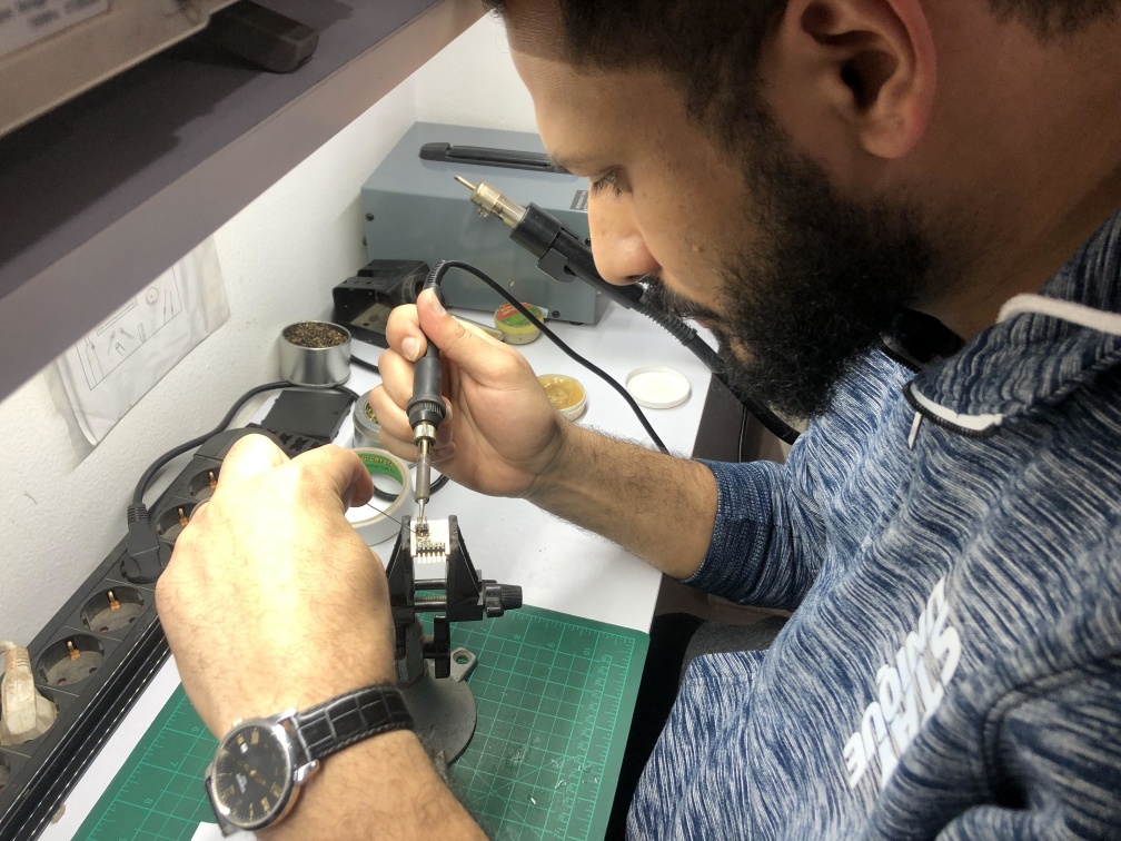
Prepare components to be soldered, and I put a small piece of double face under the PCB to fix it while soldering.
Start by putting a small amout of solder on one pad of each component.
Start soldering components from inside to outside, small to big.
Test connections with an AVO meter and ensure everything is soldered well and there's no short circuit in your board.
Programming
Now we have reached the hardest step (for me).
I started downloading the required softwares to be able to program, with a recommendation from our instructor I followed this Documentation
So the main "right" steps I made were:
I already had git installed.
Downloaded firmware.zip
Downlaod avr8-gnu-toolchain-3.6.2.1778-win32.any.x86
Extract the Atmel AVR toolchain in C:\Program Files
Download Gnu Make
Install make in C:\Program Files (x86)
Downlaod avrdude latest version.
Extract avrdude in C:\Program Files
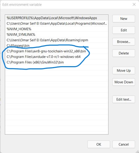
Add gnu, toolchain and avrdude to path. (open start menu and type "edit the syste environmental variables" > click on environmental variables > click on path then click edit > then browse and add files as the picture shown).
Download atmel studio.
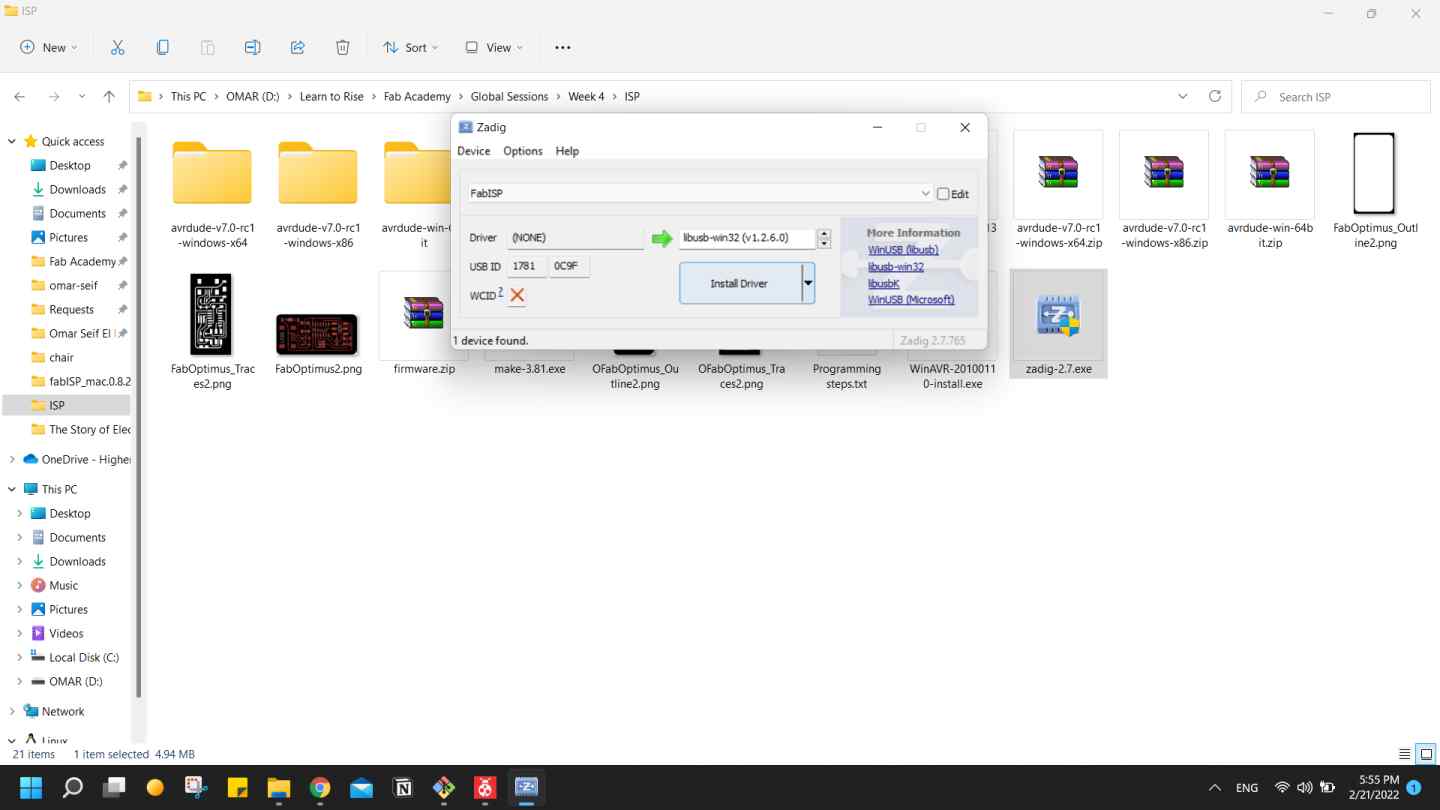
Download zadig-2.7.exe.
I have made a few mistakes in this step I will add them at the Challenges section to leave this section for correct documentation.
> Don't install WinAVR, please check Challenges section.
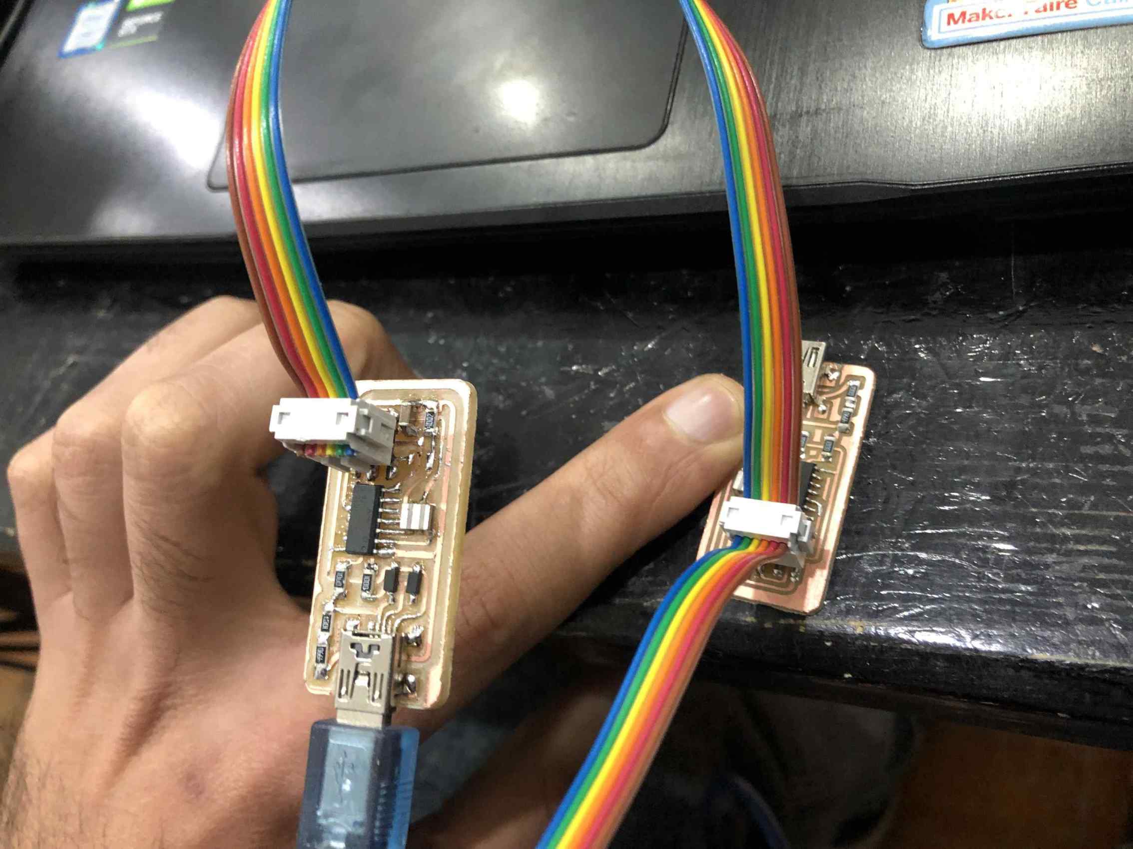
I was trying to program my board using Atmel ice programmer but I failed to do that, but with the help of our instructor my colleague Omar Senbisy
was able to program his board with Ateml Ice using microship studio.
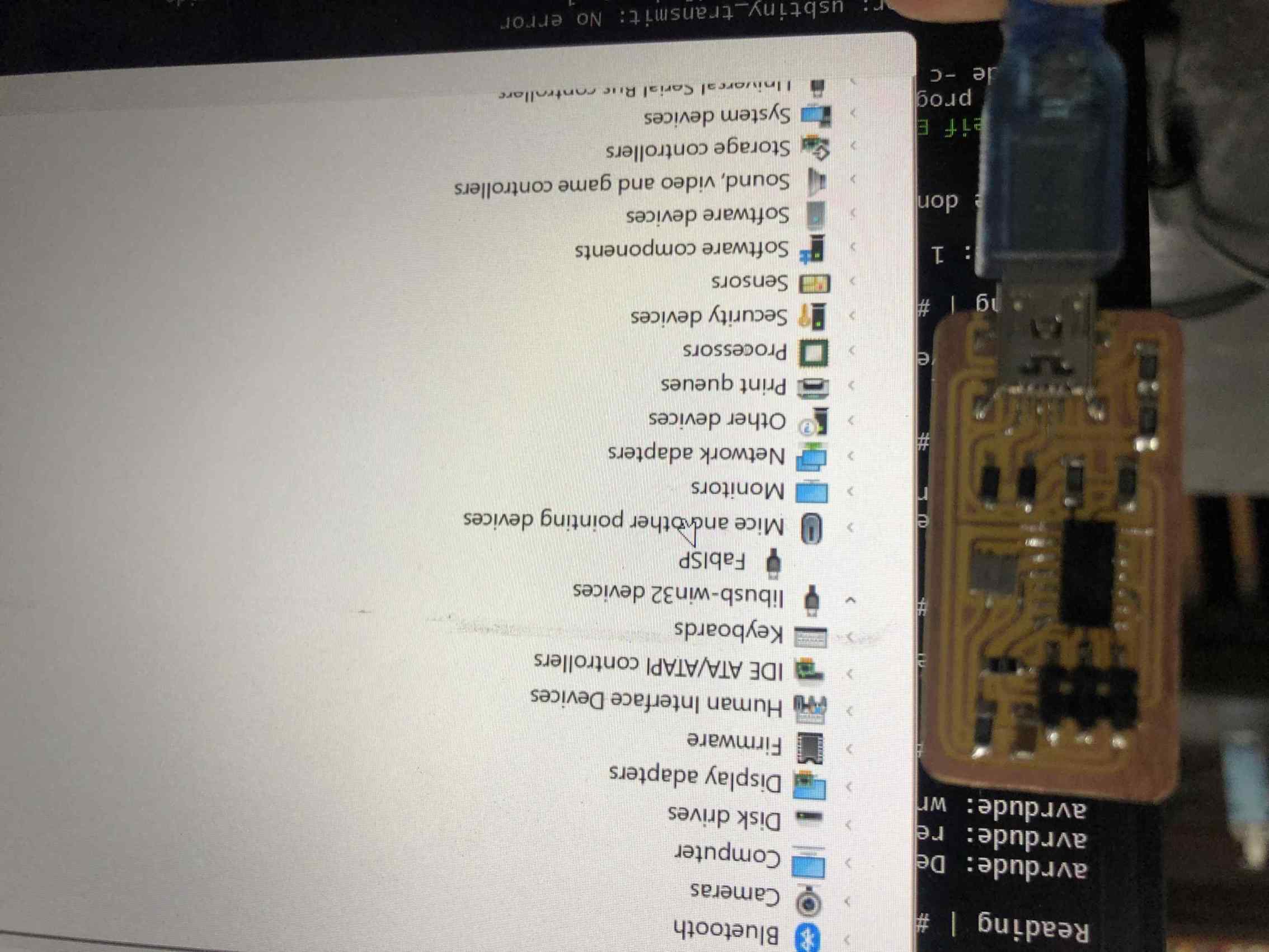
So I used his board as a programmer to program my board so I had to install the driver with zadig.
Plug the board then open zadig it will detect FabISP and move the arrow down to get the libusb-win32(v1.2.6.0) driver and click install.
By following FabISP: Programming
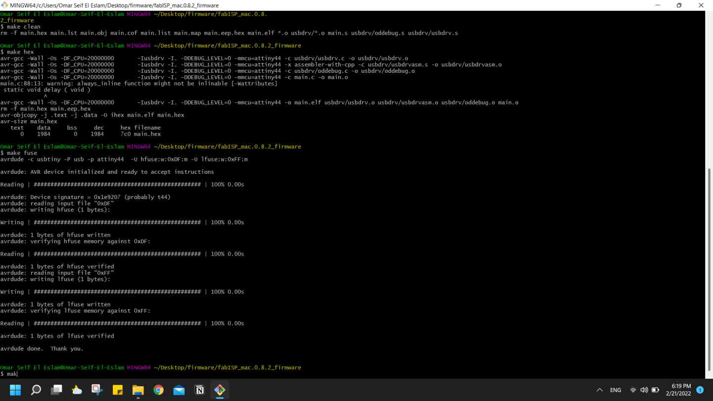
tutorial I was able to program my board, I only edited the Makefile by Removing the "#" in front of the line with "usbtiny" in it and add "#" to beginning the line with the "avrisp2" in it.
I went to firmware folder where the Makefile is located and left mouse click and choose git bash here.
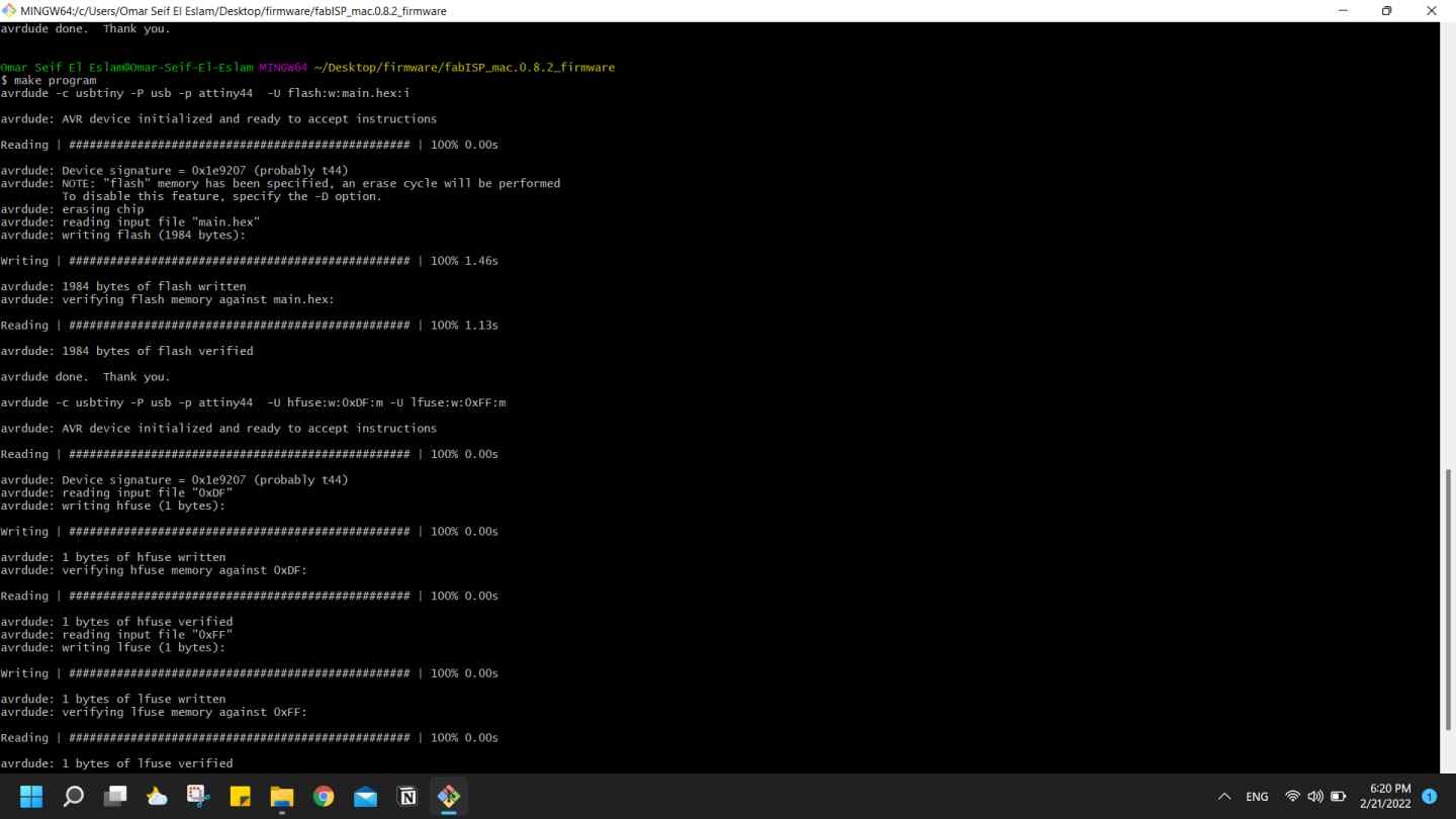
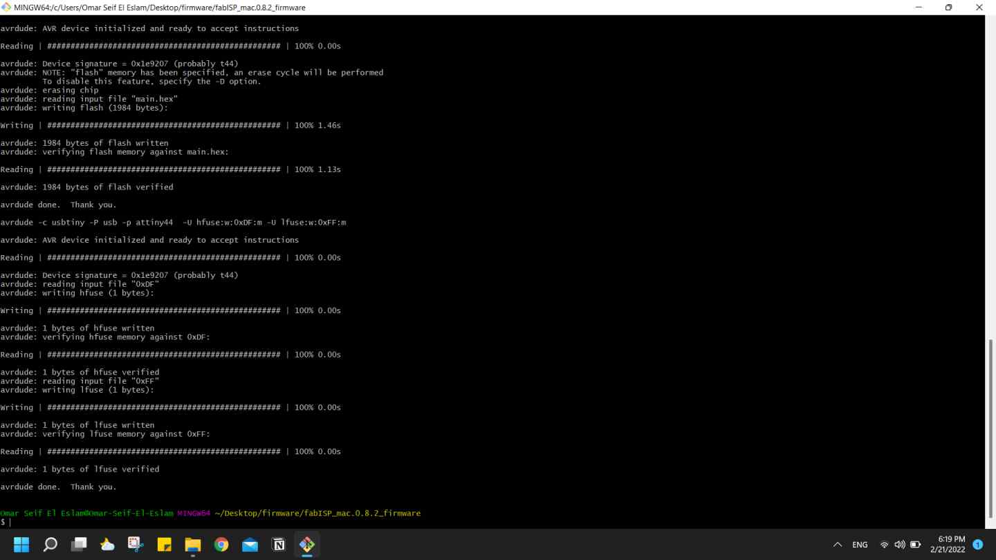
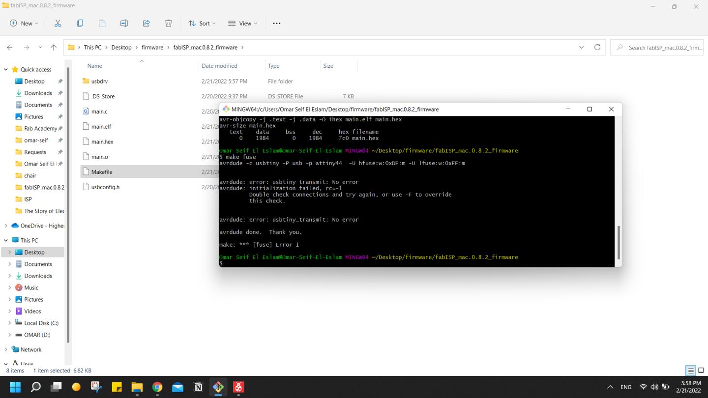
make clean > make hex > make fuse > make program, and everything worked.
I got some errors but it's related to my previous trials I will mention how I solved them in the Challenges section.
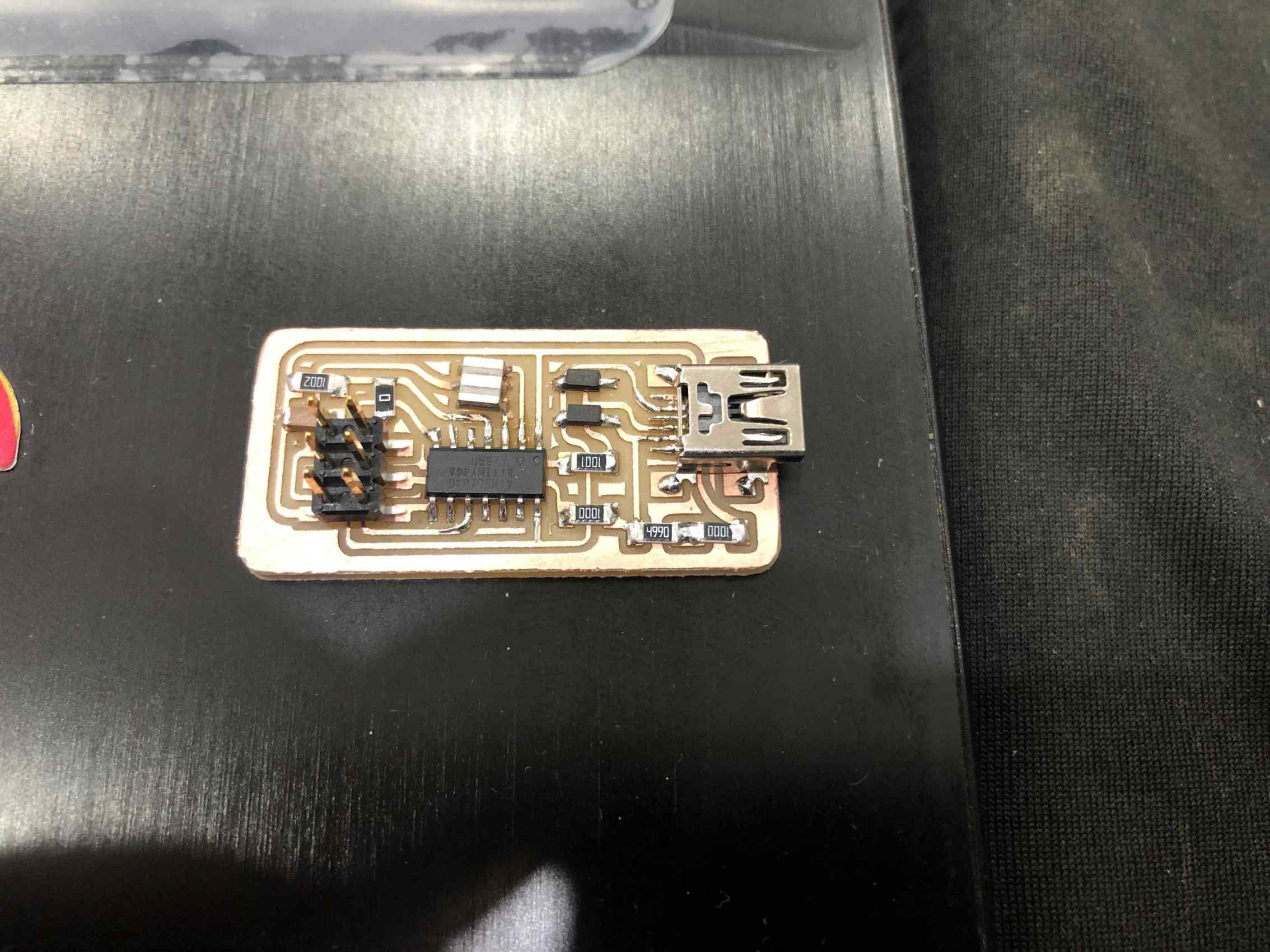
Finally it works, so I removed the 0 ohm resistor and gave it to Moiz
to use as a programmer and it worked.
UPDI
We decided to a UPDI programmer.
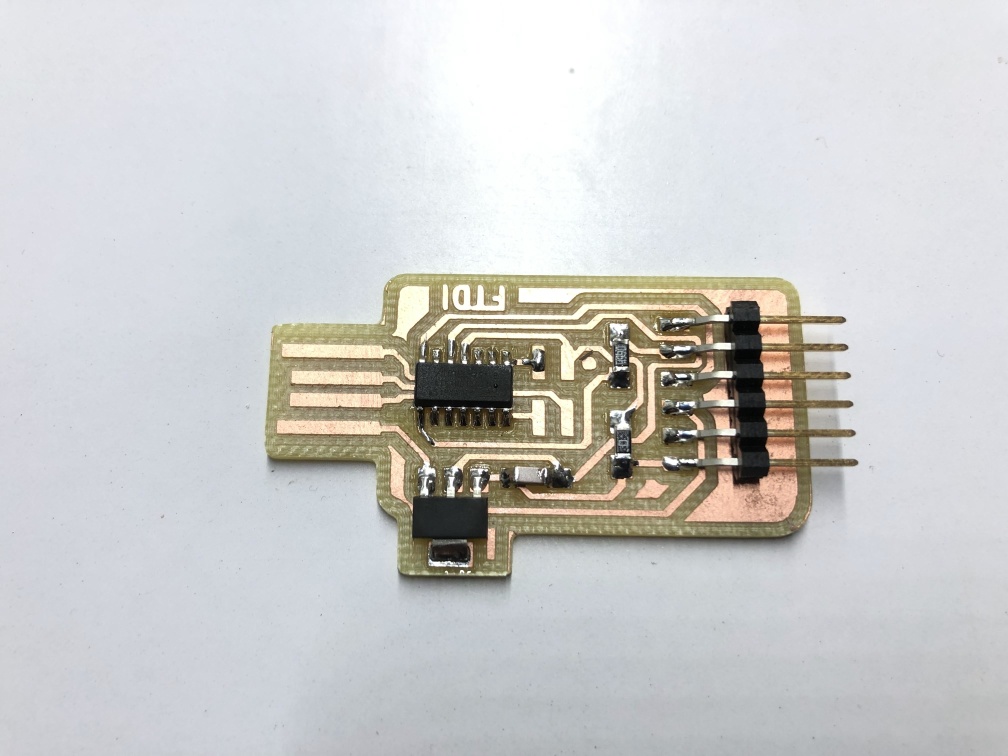
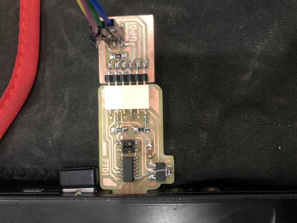
So we started with bridge D11C-based serial to UPDI bridge with FTDI socket.
Then the Serial to UPDI.
Milling
Our instructor have edited the design to replace the regulator with the package footprint that we have in our inventory.
Do the Same steps as group assignment with mods to fabricate the board.
Soldering
Prepare components to be soldered, and I put a small piece of double face under the PCB to fix it while soldering.
Start by putting a small amout of solder on one pad of each component.
Later I changed the FTDI connector in the bridge to female connector.
Programming
By following the Flashing bootloader steps from Bridge Serial D11C Documentation
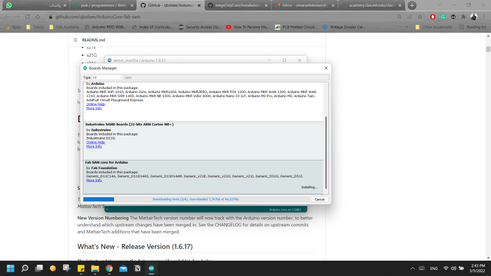
I went to ArduinoCore-fab-sam
and added the URL https://raw.githubusercontent.com/qbolsee/ArduinoCore-fab-sam/master/json/package_Fab_SAM_index.json
to Additional Boards Manager URLs" in the Arduino IDE > File > preferences.
Then from Tools > Board > Boards manager I searched for Sam and installed the fab sam core.
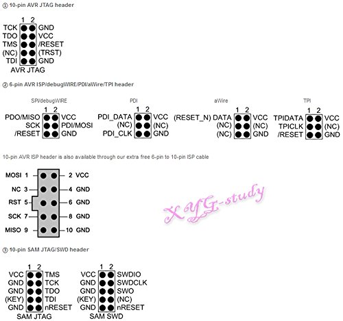
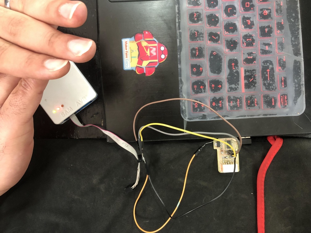
Then connected the Atmel ice programmer to my bridge, and inserted both of them in my laptop USB ports.
The SAMD11C chip works with 3.3V So we soldered a wire before the regulator to connect it to the 5V in atmel ice.
Another solution would be to supply it with a 3.3v directly, maybe from an arduino board.
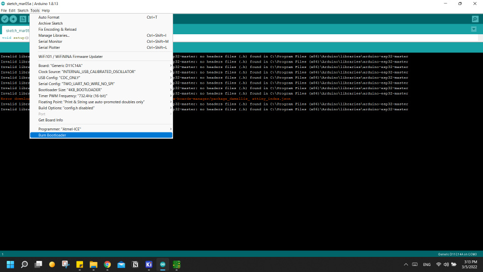
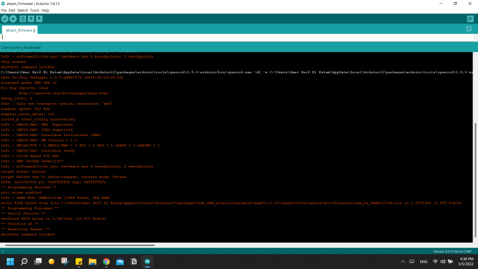
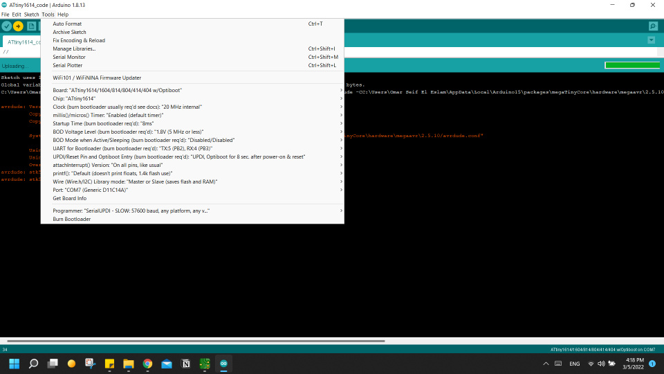
Select chip setting from arduino IDE > Tools, and set the programmer to atmel-ice then click Burn bootloader
After burning bootloader we don't need atmel-ice anymore, only the bridge inserted in the USB and upload firmware using arduino.
I got the firmware code to upload on the board from SAMD11C_serial.
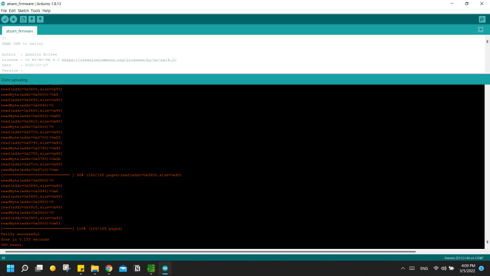
With the same setting but selecting Generic D11C14A from Port, and no programmer needed and then click upload.
Now our programmer is set and we want to test it on a board, So our instructor made a board with ATtiny1614 so we test on it.
Import the chip core to arduino http://drazzy.com/package_drazzy.com_index.json and from boards manager install megaTinyCore by Spence Konde.
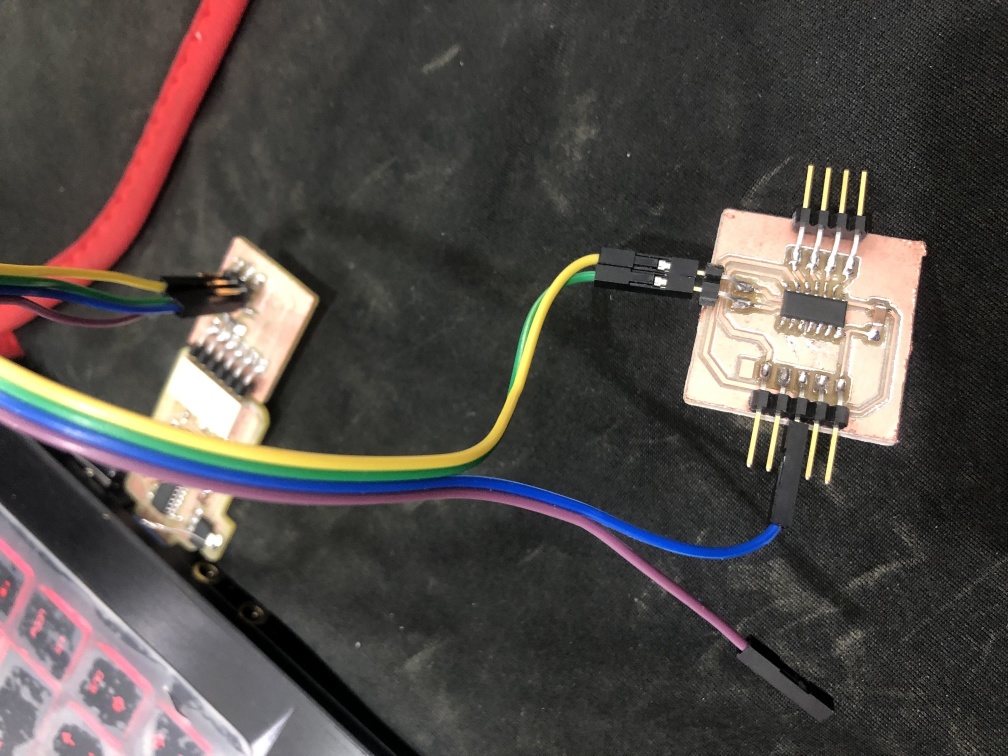
Connect the the bridge to USB > then the Serial to UPDI adapter to the programmer > then connect it to the ATtiny1614 board.
Then I copied the code from hello.t1614.echo.ino
to an arduino and set the setting in Tools.
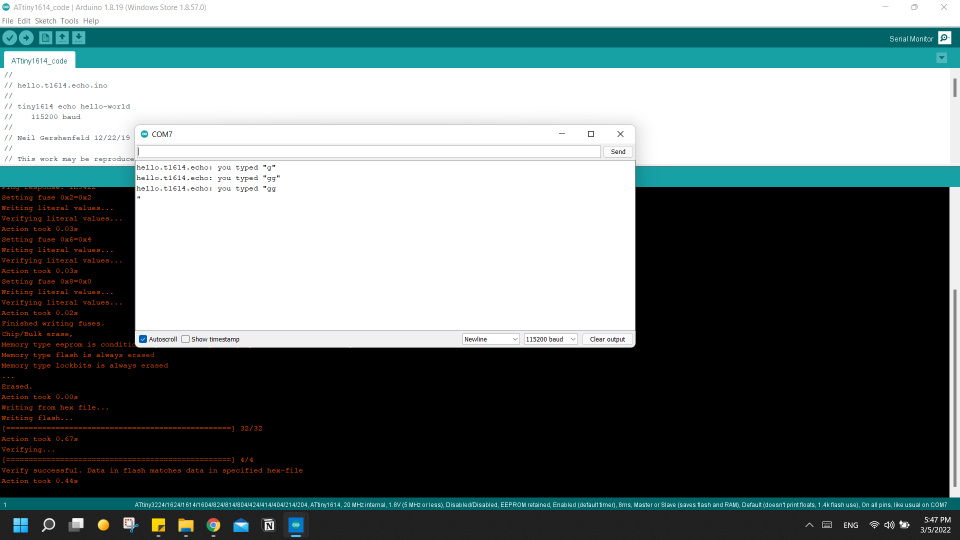
Upload using programmer then open serial monitor and type anything.
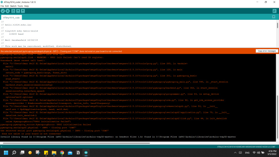
Cool, everything is working well, it didn't go smooth as it seems so check the Challenges section.
Challenges
FabISP
I downloaded WinAVR and it overwrites other downloads that you do, so when I download avrdude version 7
my git bash detects avrdude version 5 because that's what's inside the WinAVR.
and while trying to use atmelice_isp as a programmer in the Makefile it wasn't available because it's in avrdude versions after 6.3 or so.
So I uninstalled WinAVR and removed its folder from C: partition.
First I replaced avrdude files inside WinAVR but that didn't solve it so I removed it totally.
when make fuse after uninstalling WinAVR it detected atmelice_isp but still another problem so I gave up on atmel ice.
With our instructor, tried to program the board with microship studio but it didn't detect atmel ice on my PC and detected it on my colleague Omar Senbisy
so I gave up totally, looks like my laptop doesn't like atmel ice and liked FapISP more.
First time I tried to program my board using Omar's board I had an error so at this point I decided to remove/uninstall avrdude, toolchain and Gnu make and also delete them from path.
Then I restarted my laptop and downloaded everything again and done same steps in the beginning of programming without WinAVR this time.
Tried again and it worked verywell.
UPDI
I had a problem with my laptop recognizing the atmel-ice programmer, it appears device manager but the driver isn't right, So I uninstalled the driver of (interface 0) from device manager, then it worked because when I unplugged it and replugged it again the right driver got installed.
Seconed issue is that after burning the bootloader and uploading the firmware when I tried to program the ATtiny1614 it didn't see the board, after inspection with our instructor it appeared that I didn't solder all pins of the FTDI connector when replacing the male headers with female headers,
there were one missing connection so after soldering it it worked right away.
