Computer-Controlled Cutting
Assignment requirements:
Group Assignment
- Characterize your lasercutter's focus, power, speed, rate, kerf, and joint clearance
- Document your work (individually or in group)
Individual Assignment
- Design, lasercut, and document a parametric press-fit construction kit, which can be assembled in multiple ways. Account for the laser cutter kerf.
- Cut something on the vinyl cutter
Learning outcomes:
- Demonstrate and describe parametric 2D modeling processes
- Identify and explain processes involved in using the laser cutter
- Develop, evaluate and construct the parametric construction kit
- Identify and explain processes involved in using the vinyl cutter
Assessment criteria
- linked to the group assignment page
- Explained how you parametrically designed your files
- Documented how you made your press-fit kit
- Documented how you made your vinyl cutting
- Included your original design files
- Included your hero shots
Practice
This week we started by following a video
tutorial
recommended from our instructor for a parametric design, but as I choose to work on SOLIDWORKS
I followed the video for the dimensions and design concept and slightly changed few things.
Parametric design practice
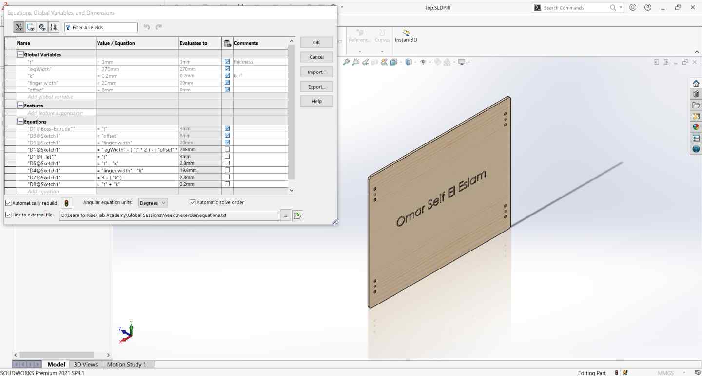
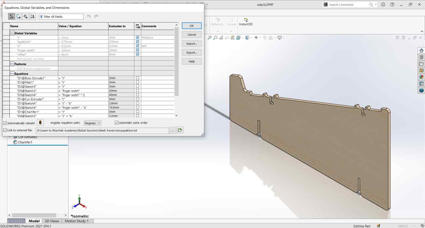
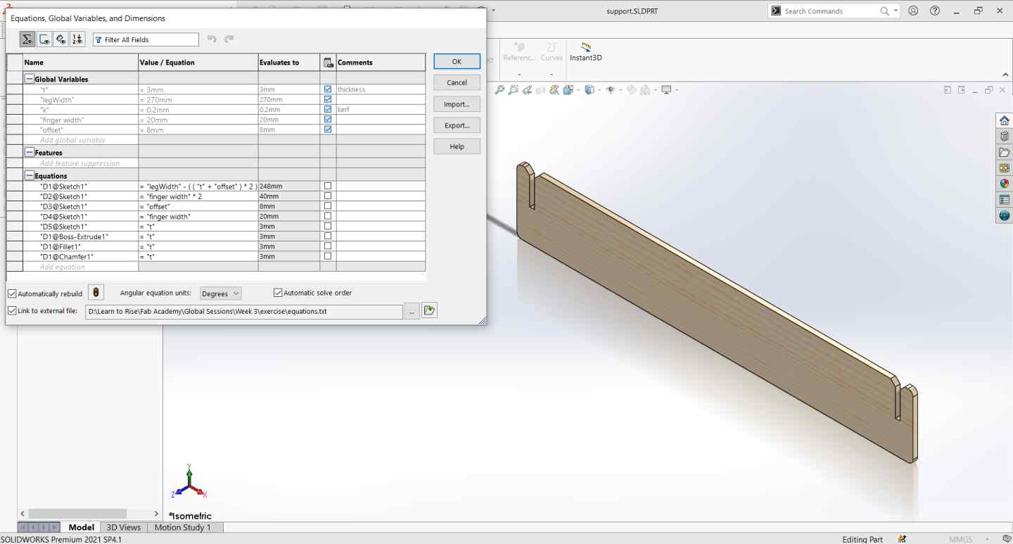
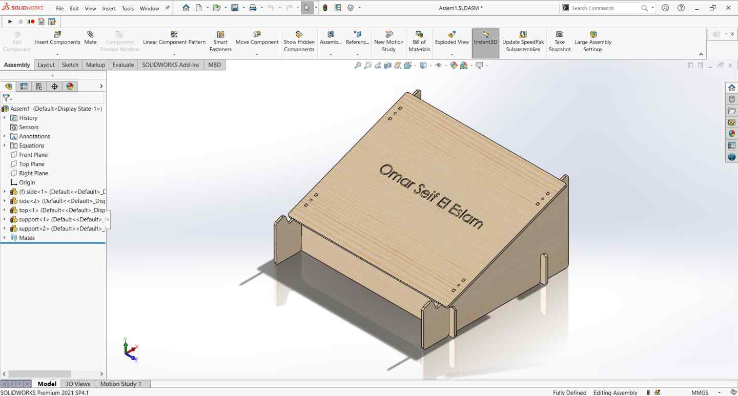
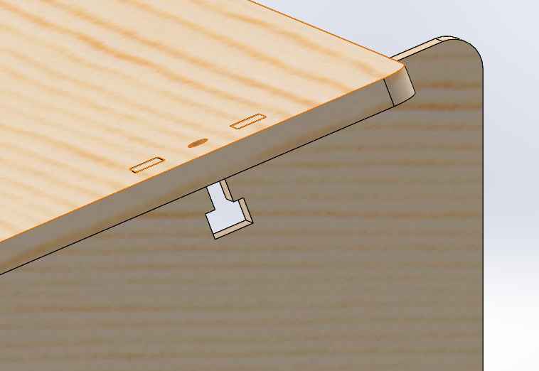
The laptop stand consists of 3 parts, So I started skectching the first part and added global variables in equations then I exported
the equations file and imported it when skectching other files and also in the assembly to make all parts linked to the same variables.
I didn't cut it after finishing directly, first we did the group assignment to determine the kerf I should
use.
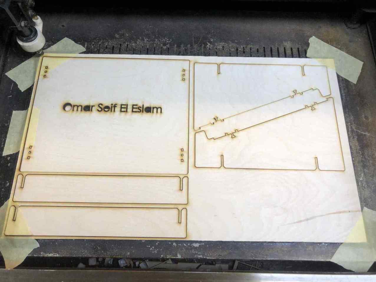
Cutting the laptop stand
After getting the joint clearance as 0.2mm from group assignment on wood I edited the kerf variable in the equation txt file to 0.2.
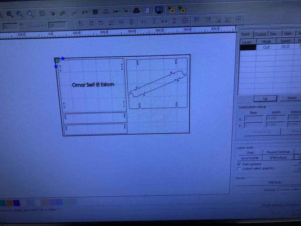
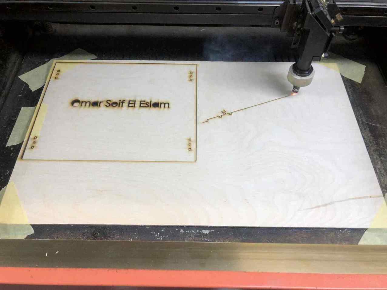
Then exported each part front face as a DXF file and then imported it to RDwork, the laser software we use, then set the speed and power.
The cut was nice and smooth, I forgot to set the text in the center to a different layer and set it to scan not cut.
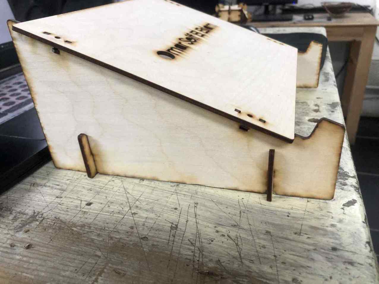
I assembled all parts together with my hand, I had to press the pieces to fit together but I didn't use any external tools
so the fit was pretty good for me.
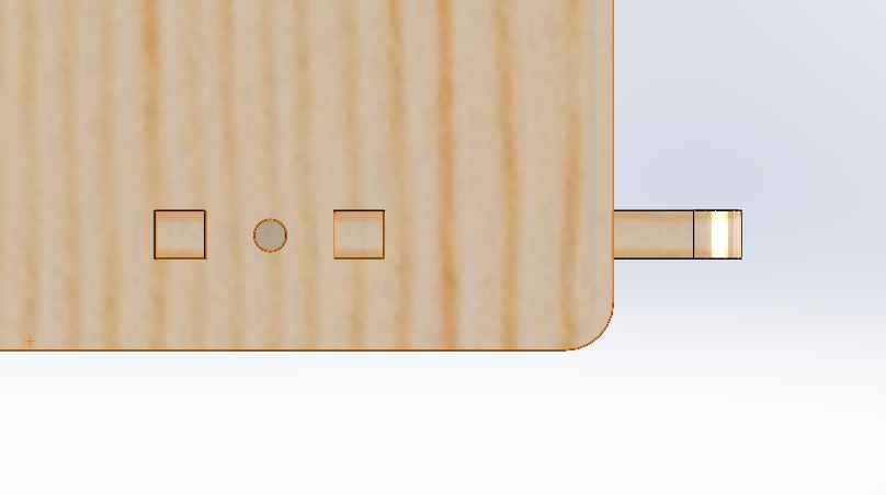
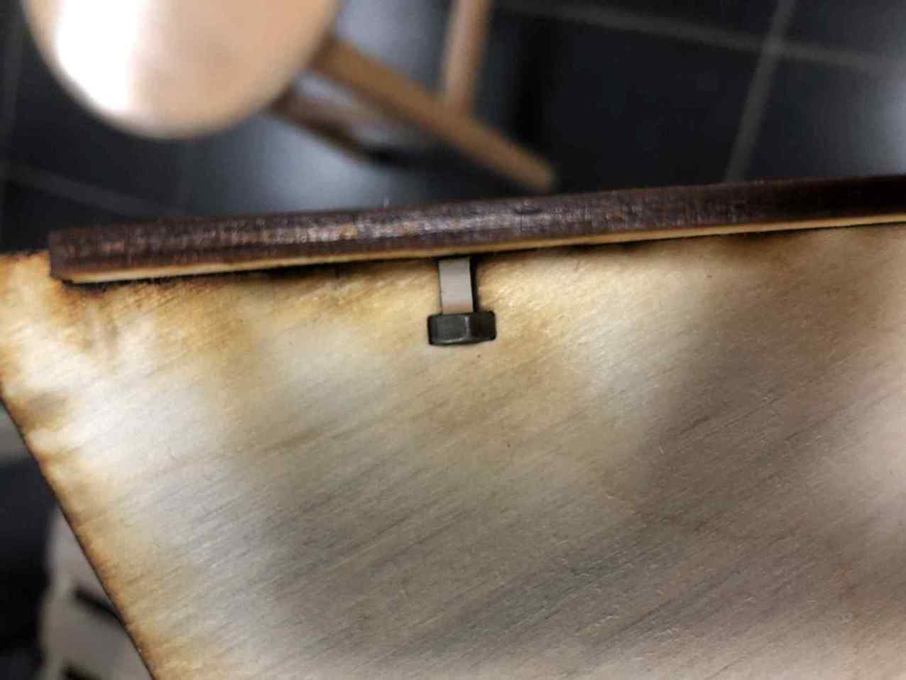
I also tried the nut slot I made and it was very good, the but fit inside it and didn't have the space to rotate at all.
Our laser machine is a bit old and it gives the burning effect on wood edges so we usually sand it to have the clean look,
but I didn't really have enough time to do that.
Group Assignment
In this week we want to characterize your lasercutter's focus, power, speed, rate, kerf, and joint clearance.
We did that on wood with our instructor, then each one got a material to work on and I got acrylic.
Focus
First information I knew that the laser machine we work on has a lens with focal length of 50.8mm.
I watched a few videos about how to determine your machine focus and I liked the ramp idea.
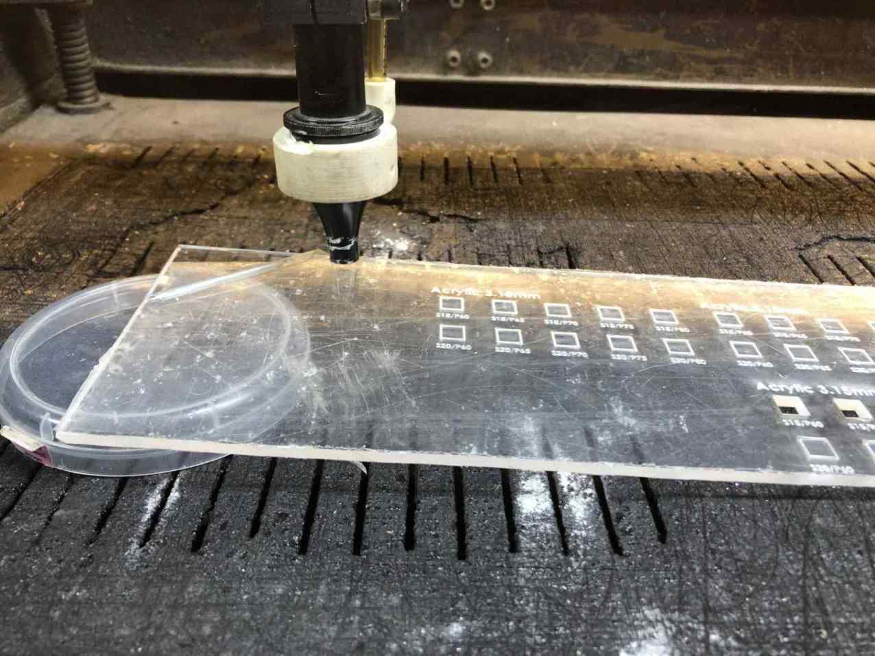
I got a scrap piece of acrylic, I put a plastic piece under one end of it to make a ramp.
Then I moved the x axis while pressing on the pulse button to generate laser beam.
This should have been my first step but I actually did it after a few trials so I wanted to document it the right
sequence but you will see a portion of the other trials in the photos.
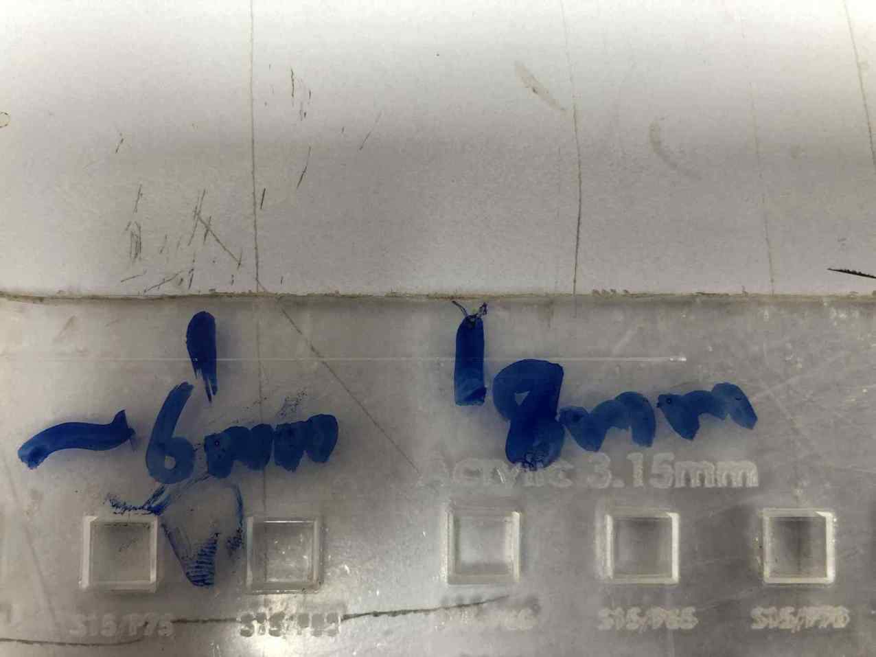
I marked a range where I think that the laser line is best.
Then I measured the approximate distance between the acrylic piece and the bottom of the laser head nozzle,
so it started from 6mm to 8mm.
So I tested cutting parameters at different focus hights to decide what gives me the best result.
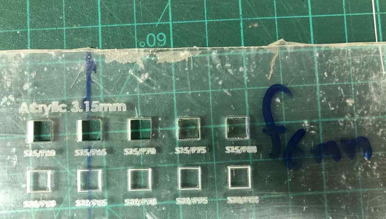
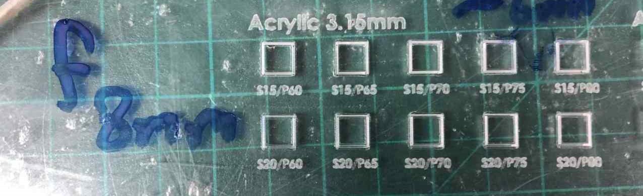
Power & Speed
I measured the acrylic thickness and it was 3.15mm,
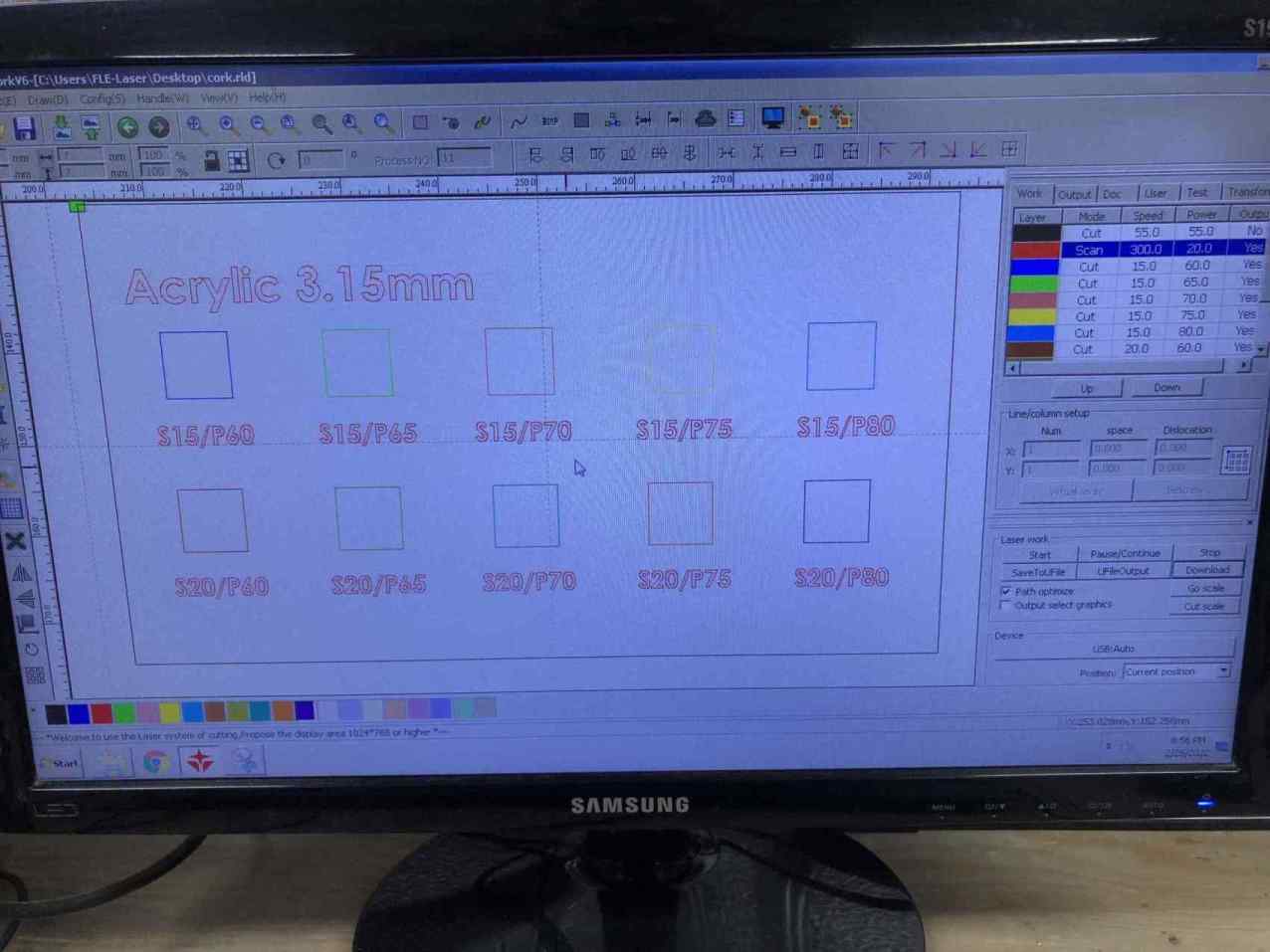
so I sketched 2 rows of square each row has 5 squares, the first row has a constant speed of 15 and power from 60% to 80%,
the seconed row has a constant speed of 20 and power varry from 60% to 80%.
I exported the sketch as a DXF file and then imported it to RDwork the laser software we use, then set a layer for each square and
set the speed and power of each, also engraved the text.
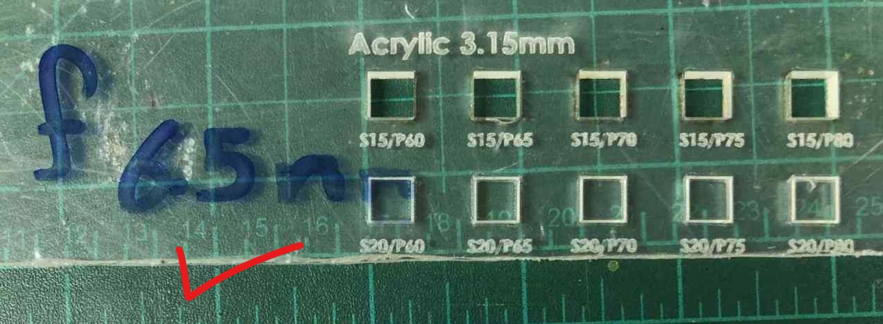
Firstly I tested like 3 times at 8mm focus and I got no cut at all, why I tested at 8mm first (because in group assignment on wood we decided that focus is 8mm ).
When I got no cuts at all I thought of increasing the power or decreasing the speed but I wanted to try at another focus so I tested with 6mm and it cut all square at the first row
only 2 of them I had to push with my finger to get them out.
So I gave it another try at 6.5mm focus and it gave me perfect cuts on all squares of the first row.
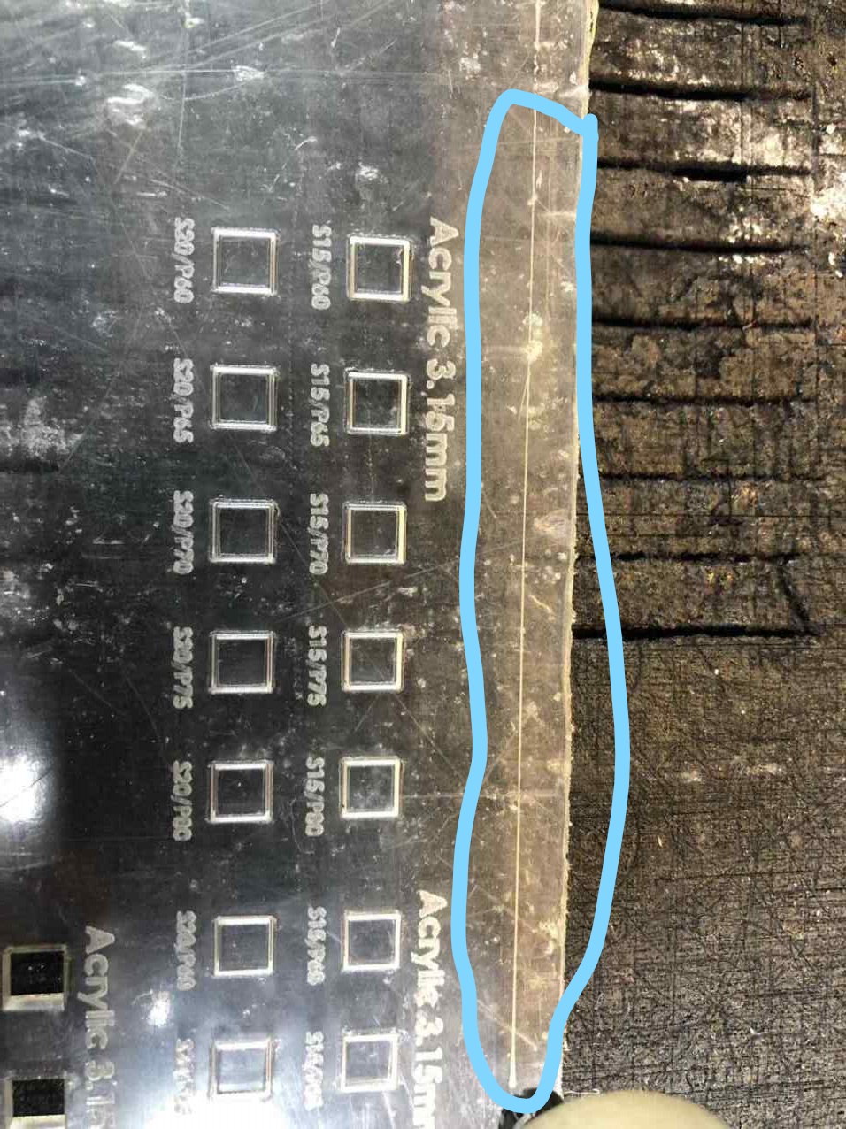
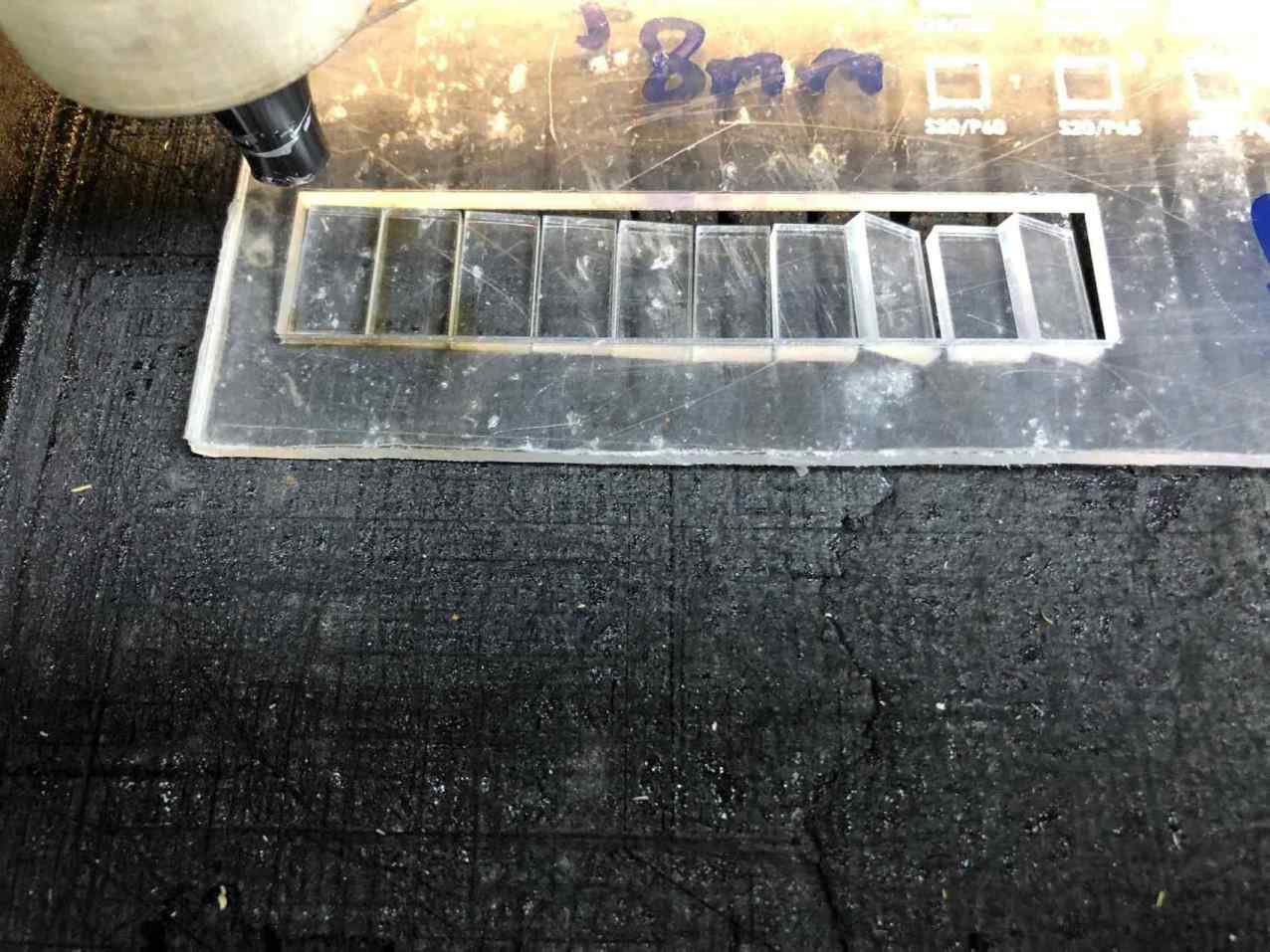
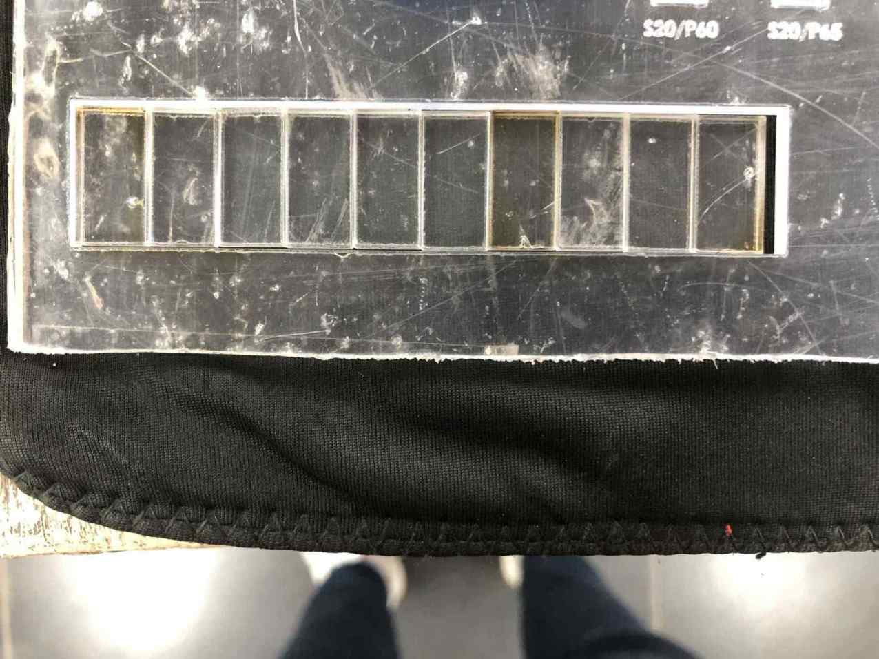
Kerf & Joint clearance
To determine the kerf I sketched a rectangle of 100mm width 9 lines inside it and a distance of 10mm between each line,
to give me 10 pieces.
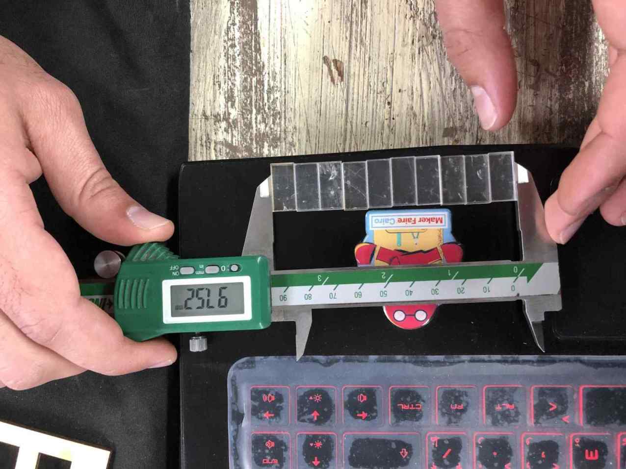
After cutting with best power and focus I choose from previous step I measured the width of the 10 pieces together
and subtracted it from 100mm then divided the result by 10.
So 100 - 97.52 = 2.48 / 10 =~ 0.25mm and that is the kerf.
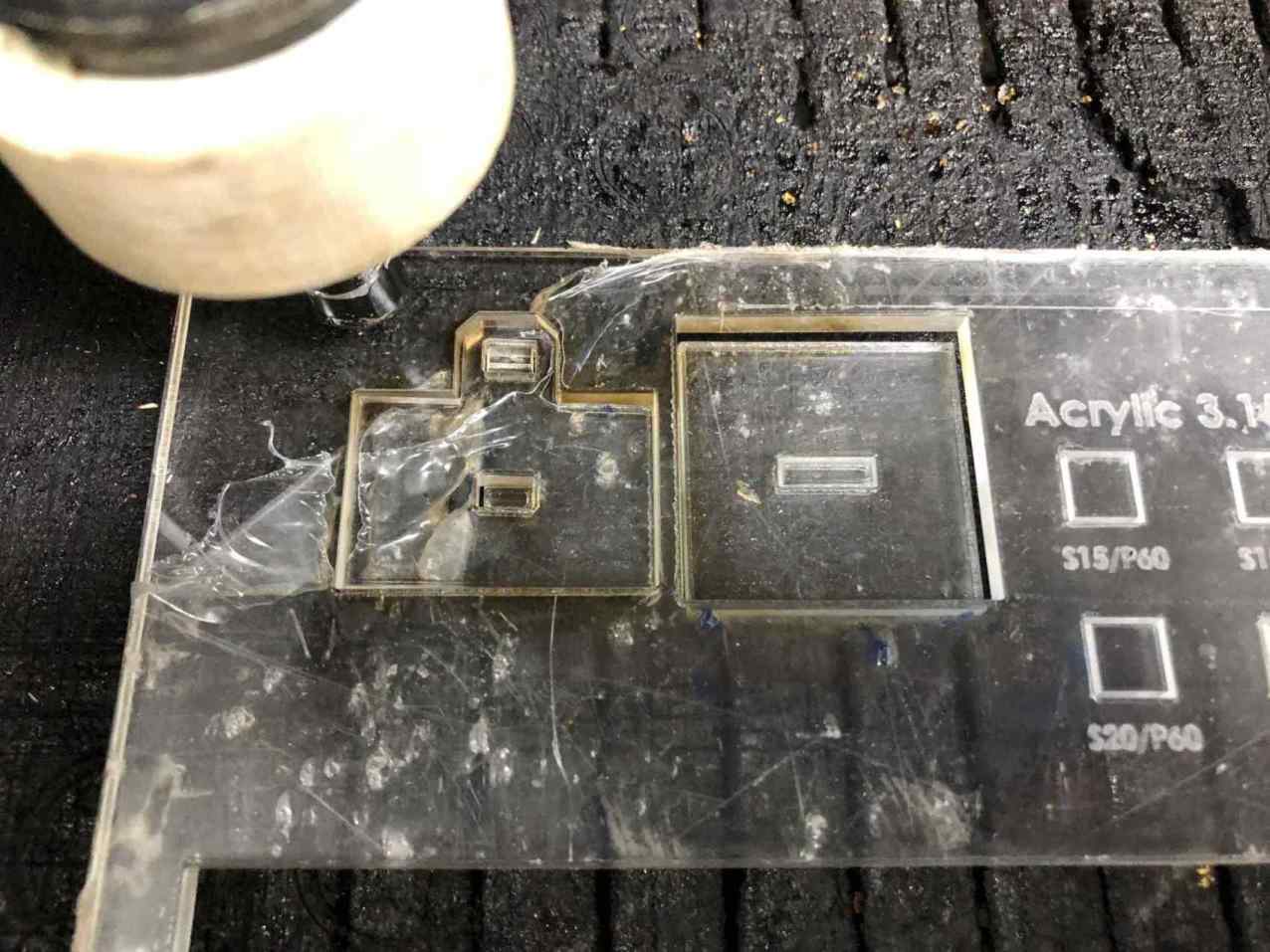
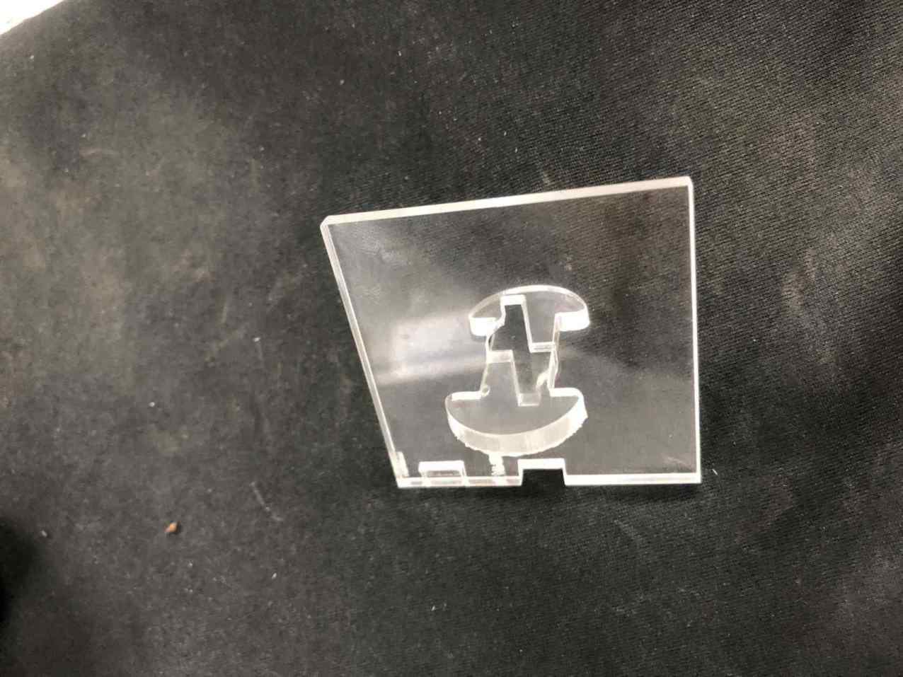
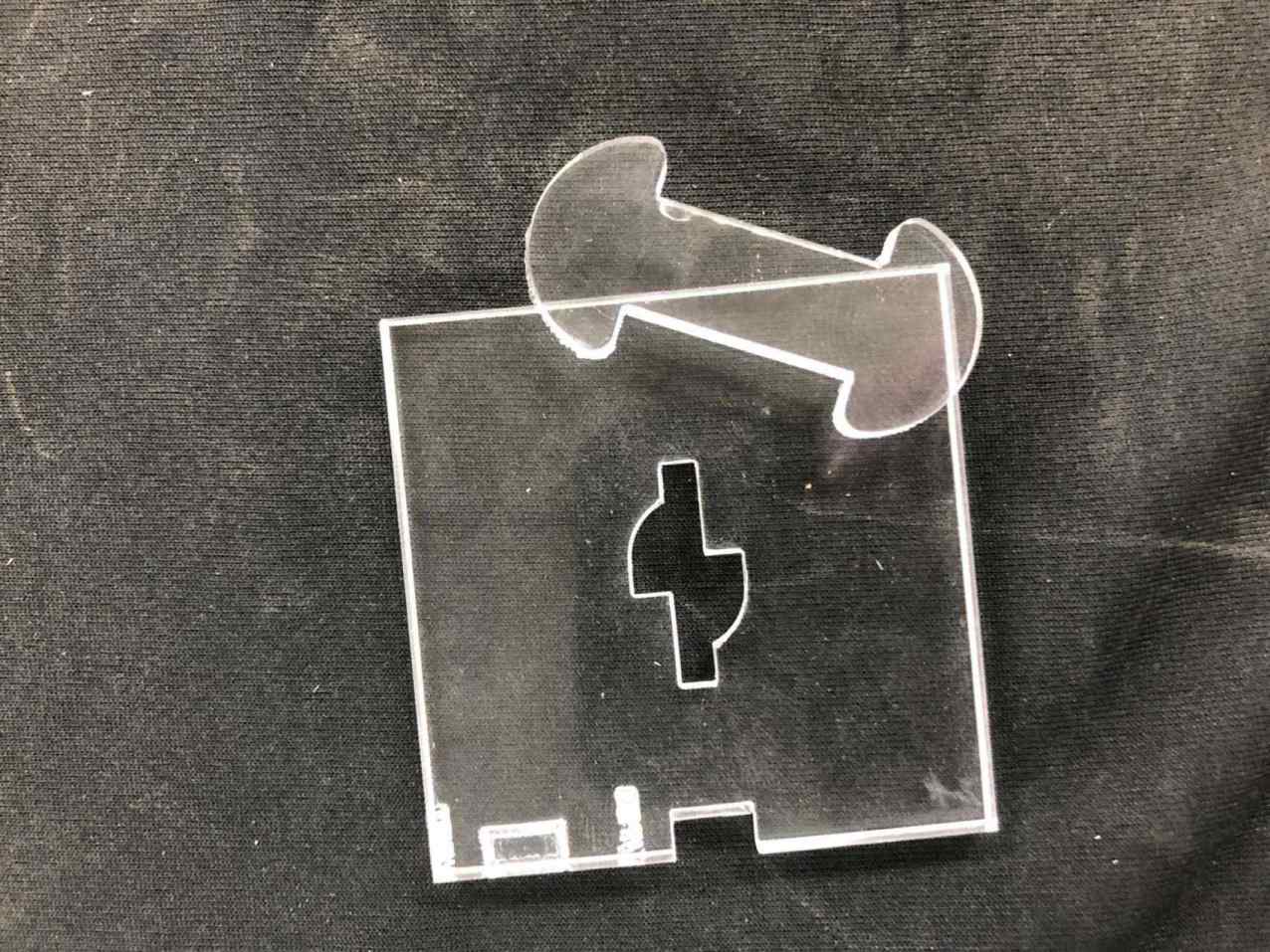
I sketched a press fit wedge joint to test the joint clearance so first time I set the kerf to 0.25mm and cut the joint.
I was not able to fit the male inside the female part, I had to give a little clearance so I set the kerf in my design to 0.2mm instead of 0.25mm.
When I set the kerf to 0.2mm and cut the female part again it fit in perfectly so I noted that the joint clearance should be 0.05mm.
Hooray!
Construction kit
First thing I did to know what will I do, I thought of a shape that I want to come out using my kit.
So I want to assemble a shape of a human so I said I want to have a circly, rectangle and square shapes.
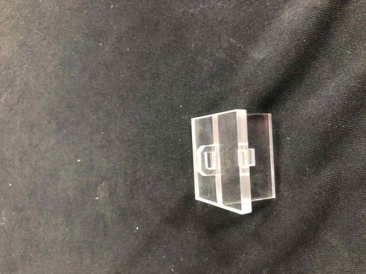
I didn't come up with the human shape I ended up with holder, stand and a good looking box shape in my opinion.
I think without the initial thought that changed through the process I wouldn't start the design at all.
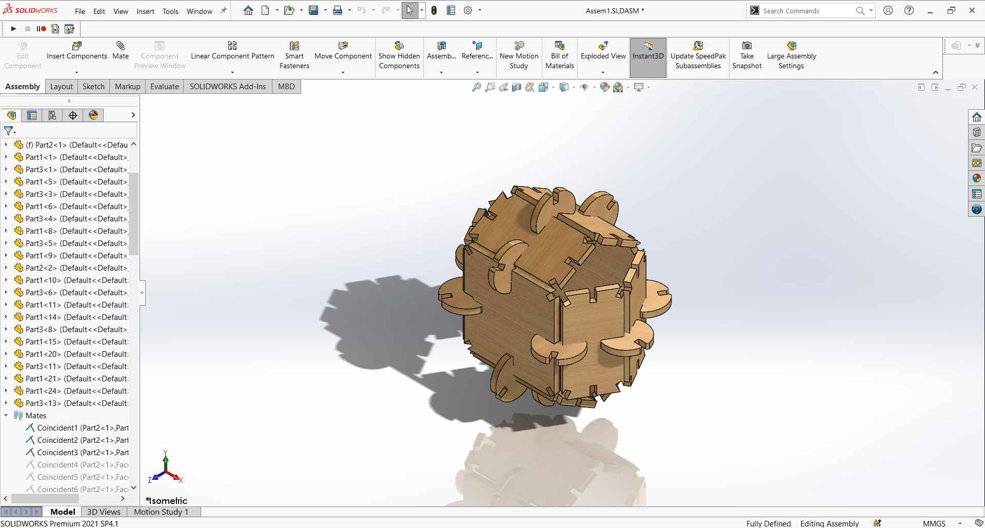
Kit design
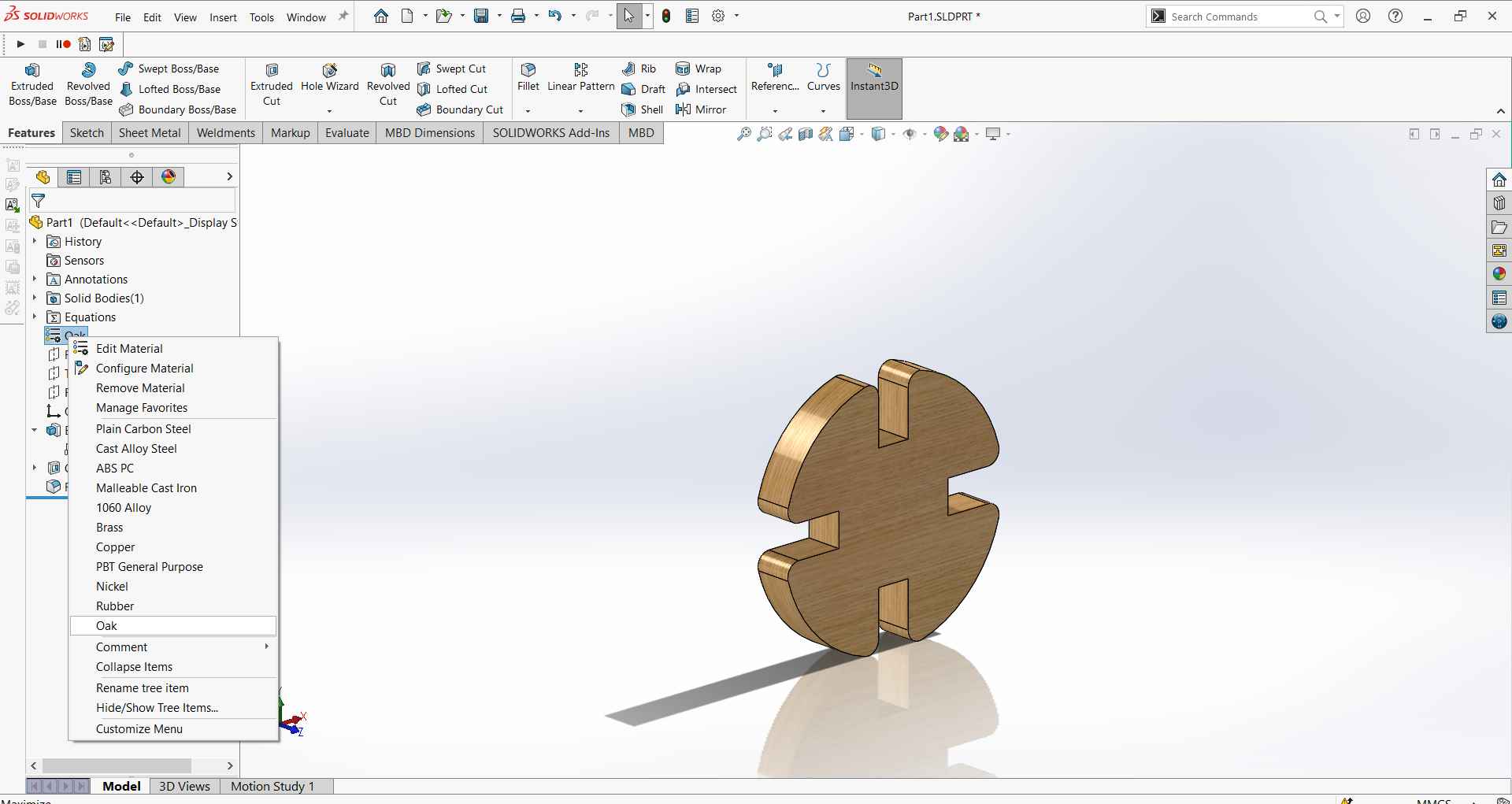
Open SOLIDWORKS new part.
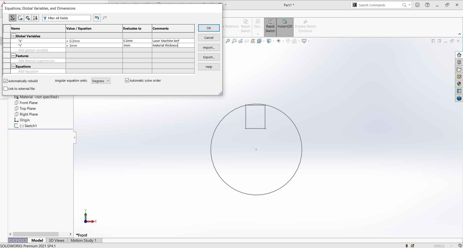
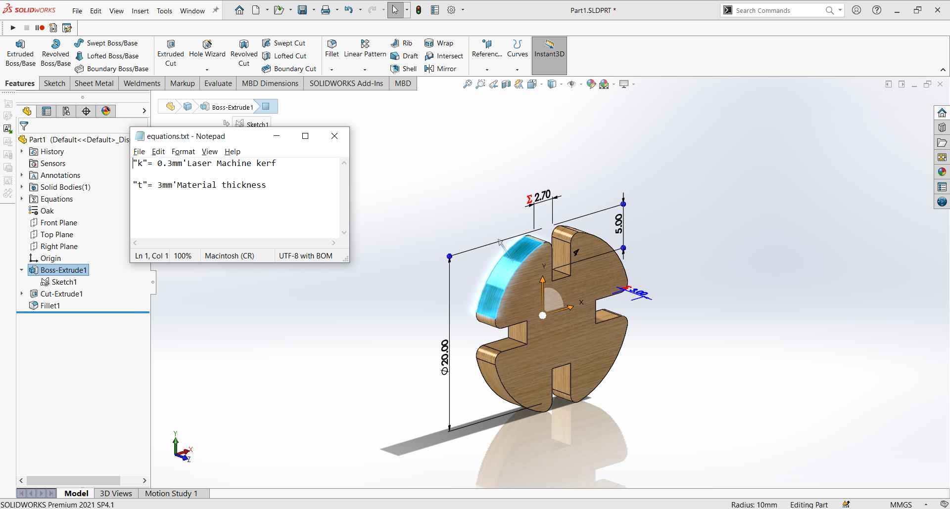
Add global variables, for me I added material thickness and kerf (joint clearance).
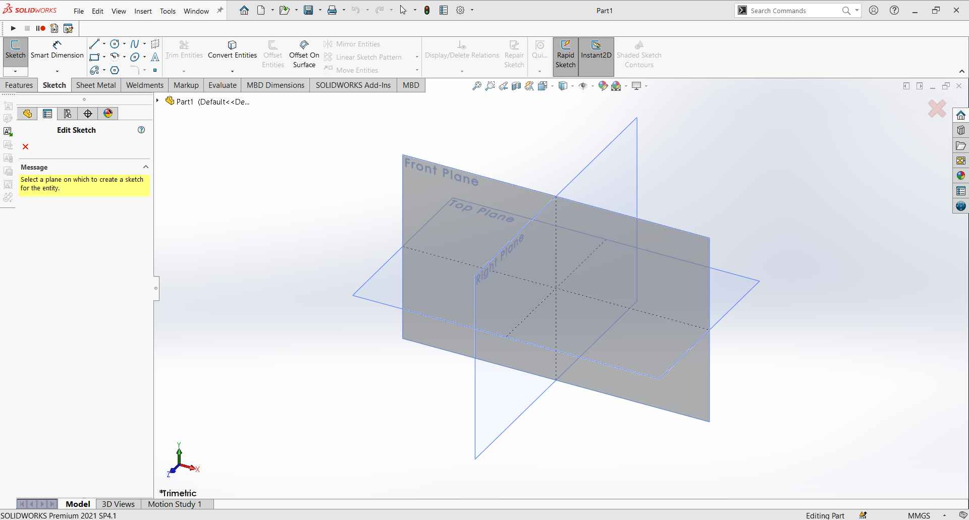
Select a plane to start skectching.
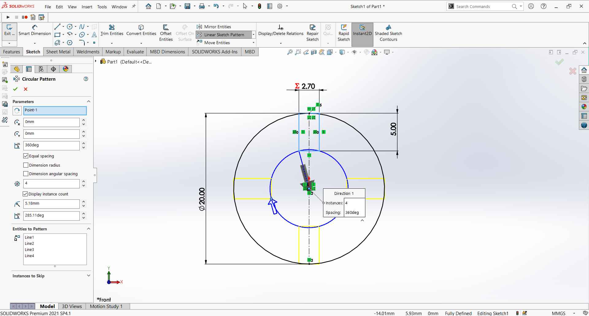
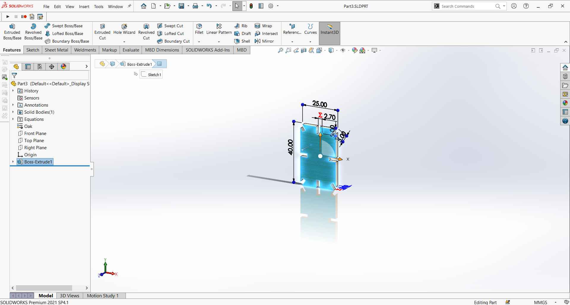
My first part is a circle, I sketched a circle then a rectangle inside it to construct the slot, and made a circular pattern of it.
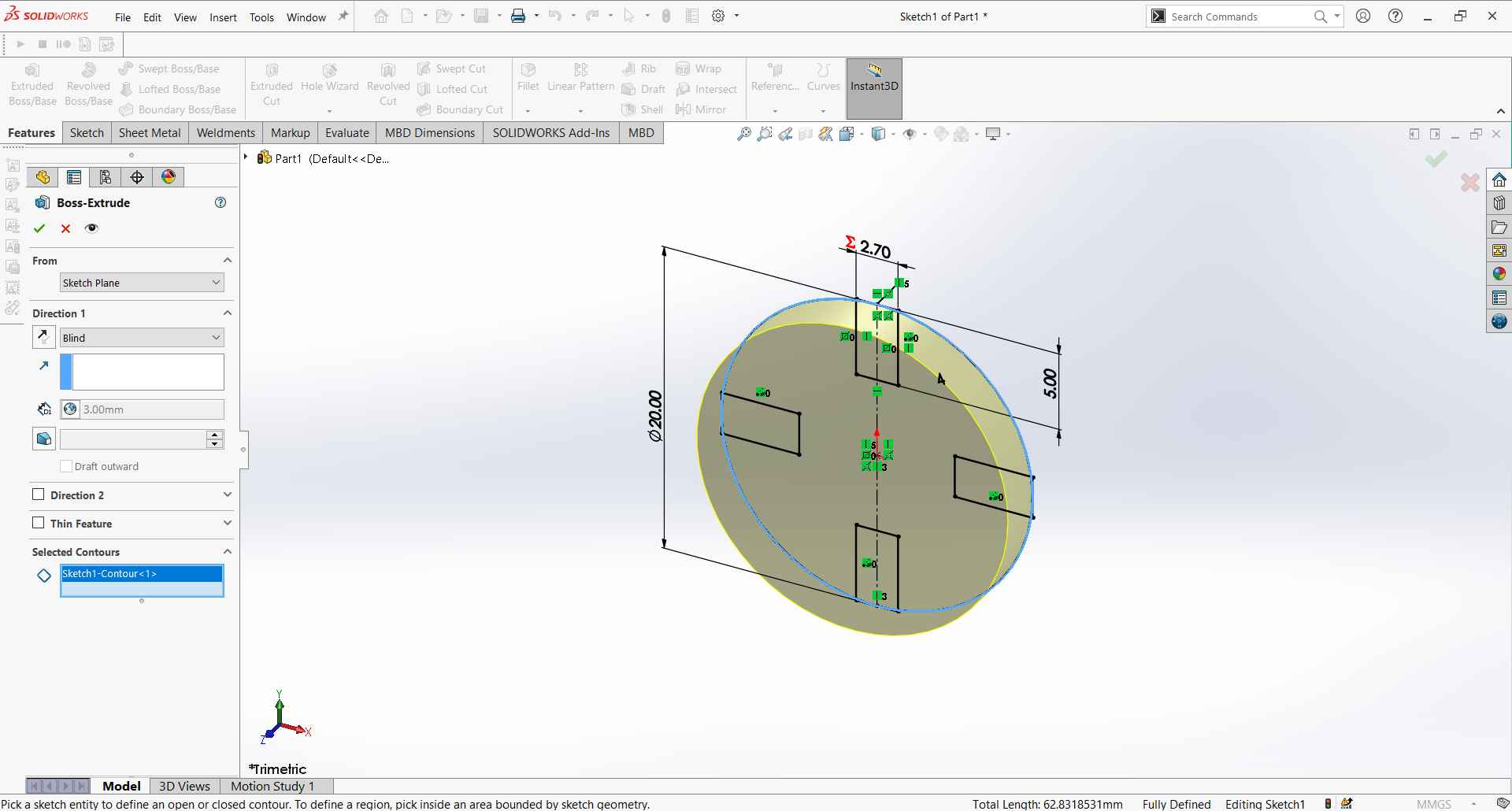
Extruded the circle.
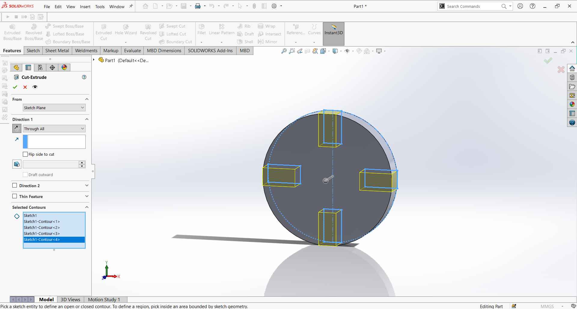
Extrude cut the rectangle slots.
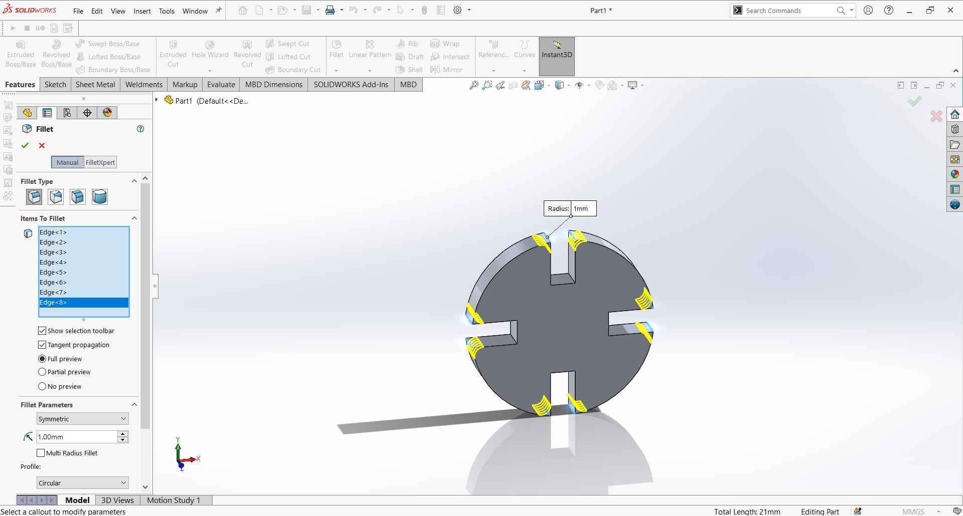
Add fillets to refine the edge.
Add material to the part to have a nice look.
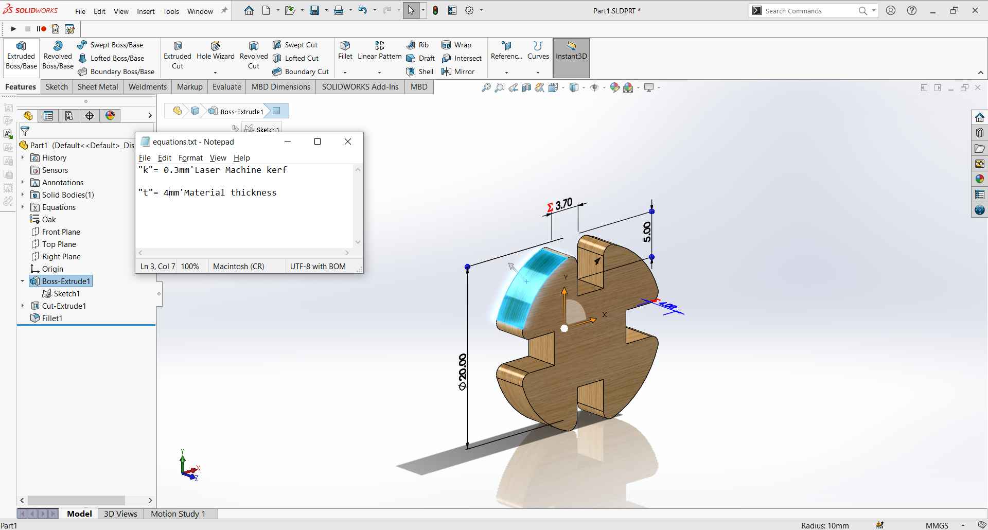
Exported the equation file.
opened the txt file of the equation and made changes to ensure everything is working well.
Opened a new part and imported the equation file I exported from the first part.
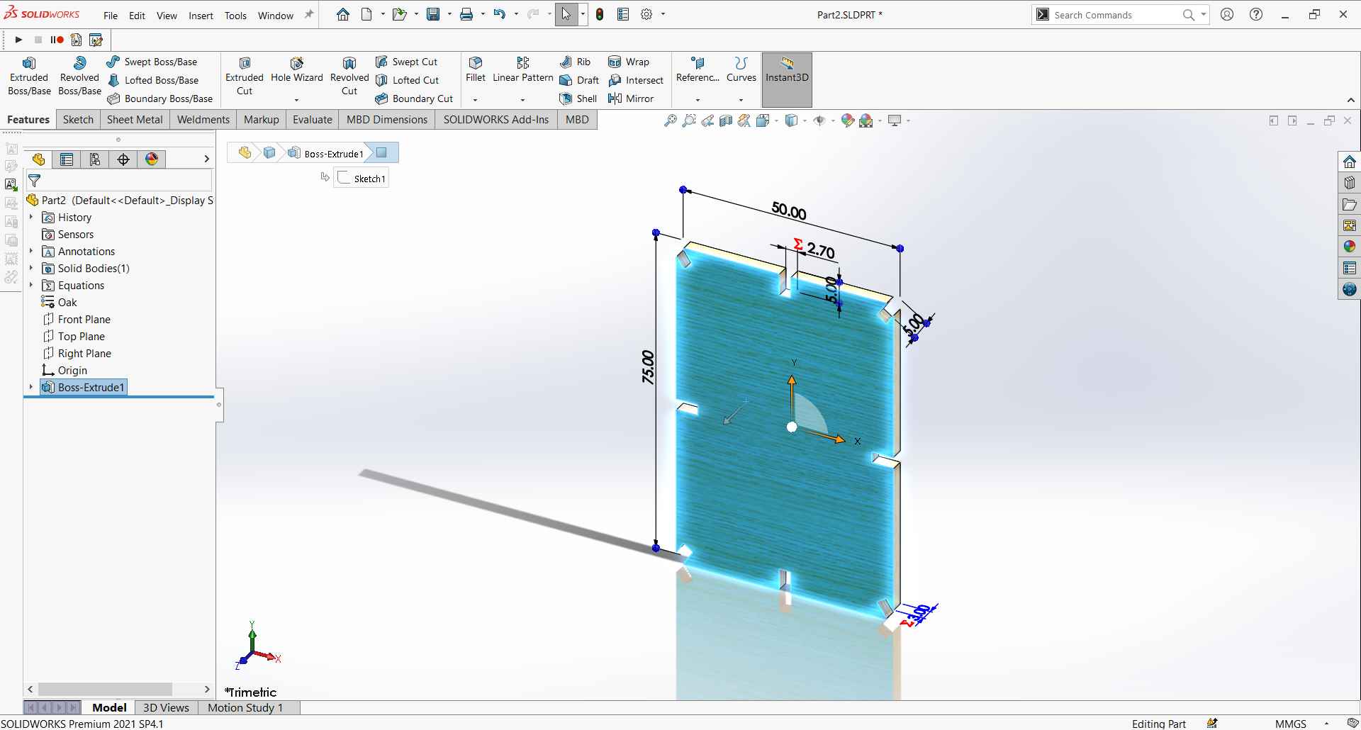
Started to sketch the square and used extrude boss and cut extrude.
Saved that part as a copy and edited it to a rectangle shape.
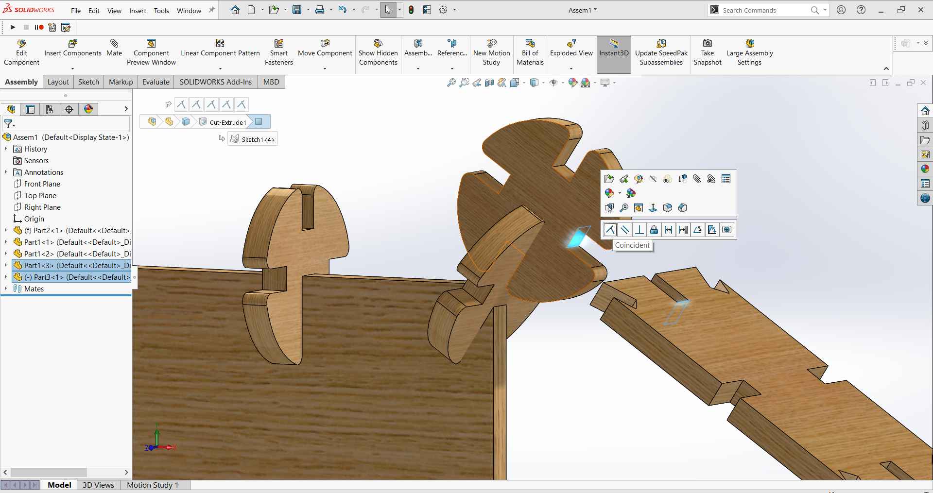
Now I have my 3 parts ready to assemble so I started new assembly and started to try some shapes.
To make a fully defined joint we use 3 mates:
Face of first part to inside side slot face of seconed part.
Face of seconed part to inside side slot face of first part.
Slot bottom face of both parts together.
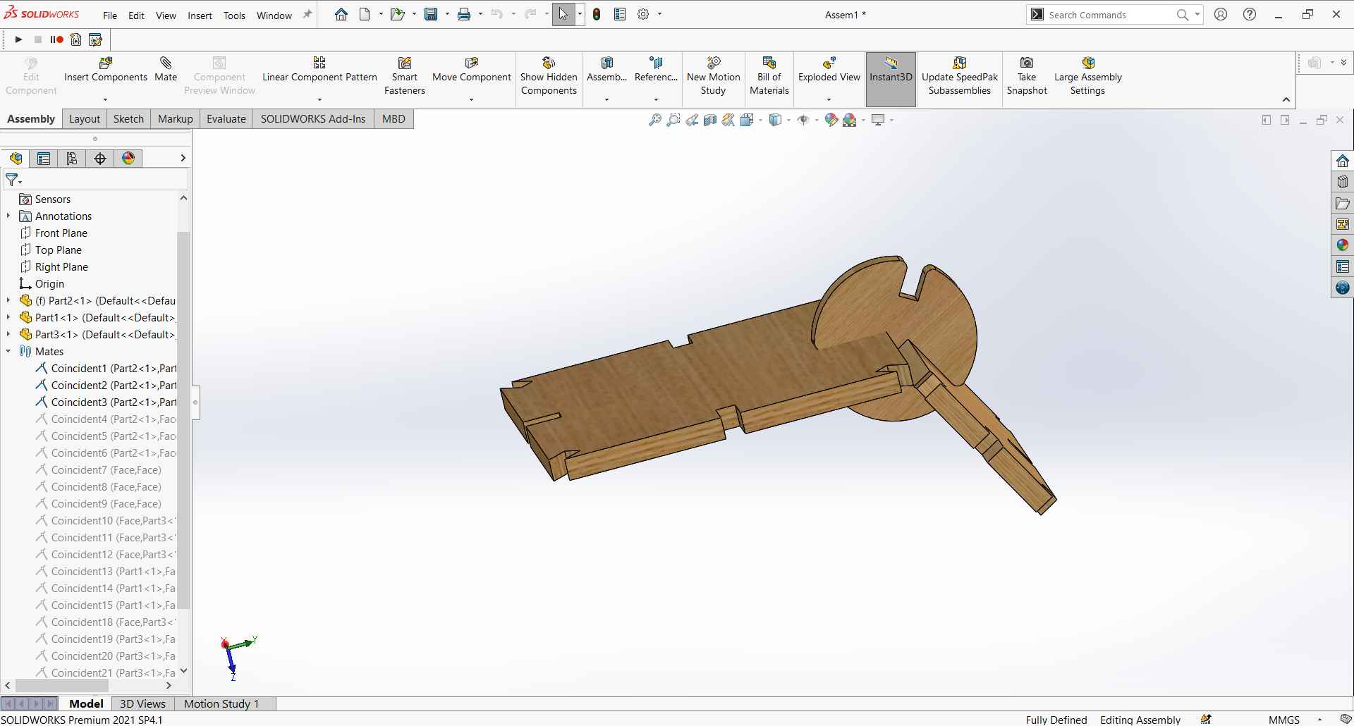
I didn't get the human shape that I wanted when I started this design so I started figuring out what other shapes can be done.
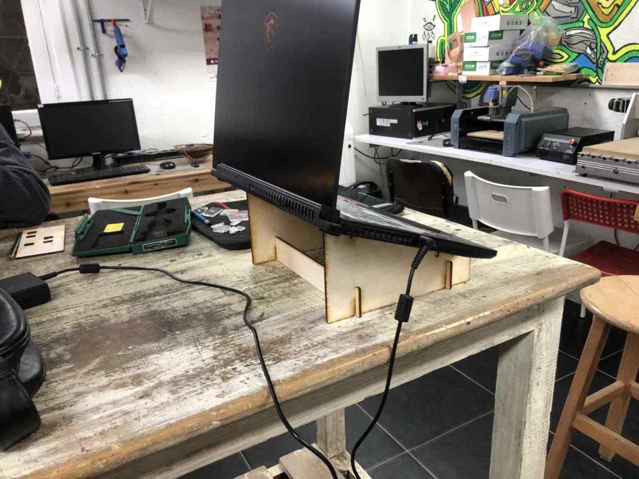
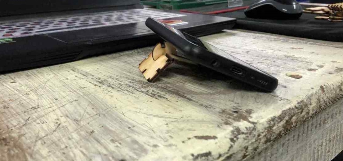
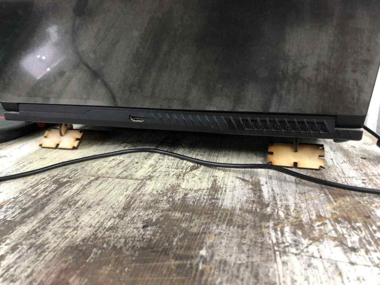
I made a shape of a mobile stand and I said if I made 2 of it, it can be a laptop stand.
and started adding more parts to get a bigger shape.
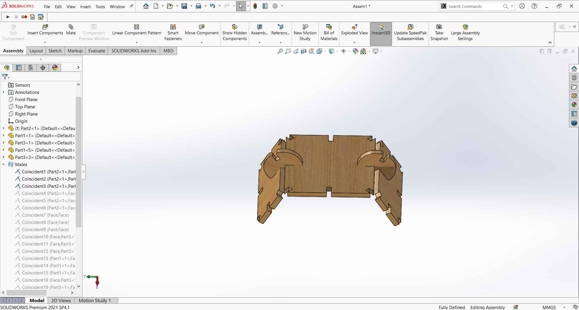
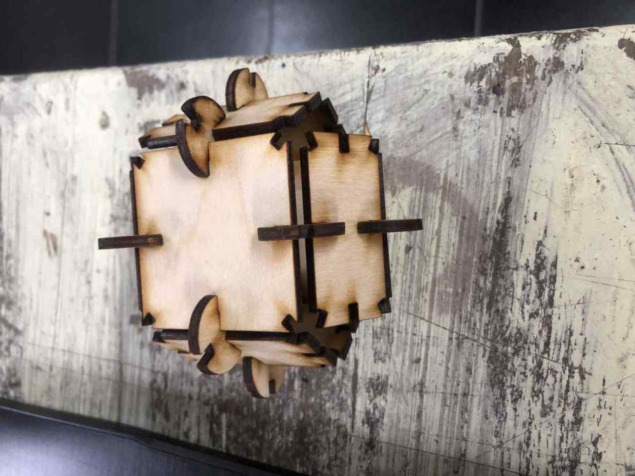
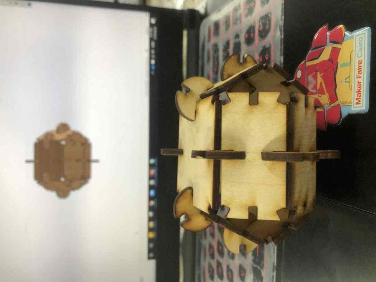
I kept adding parts untill I made a box which I liked the shape of, so I stopped there.
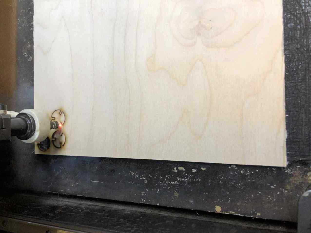
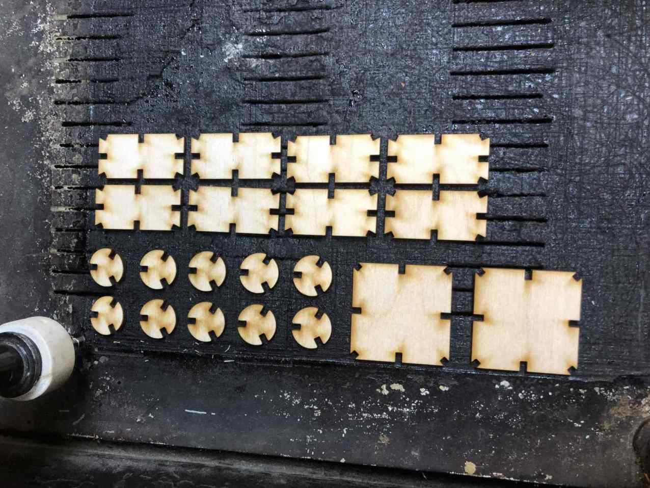
Kit cut & assembly
I exported each part front face as a DXF.
Counted the numbers of each part I need to make the box.
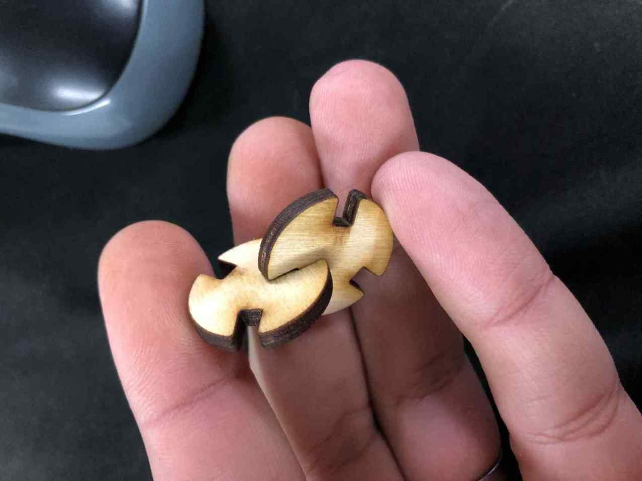
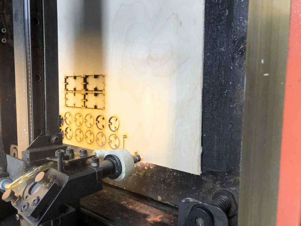
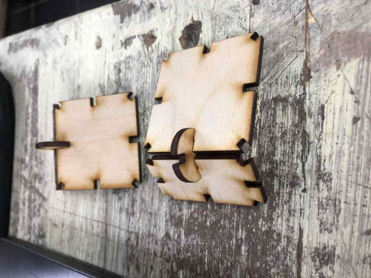
Imported to laser machine software, and tried only 2 parts first to ensure they fit good.
Fits perfectly, let's cut the rest of them.
Assembly trials and testing if it really do what I think it can do.
I liked the parametric design at this point.
Tested on a mobile and a laptop.
Assemble more to get the box.
After assembling the box I thought that I could use this box as the base element and start making more shapes.
Hooray! again
Vinyl
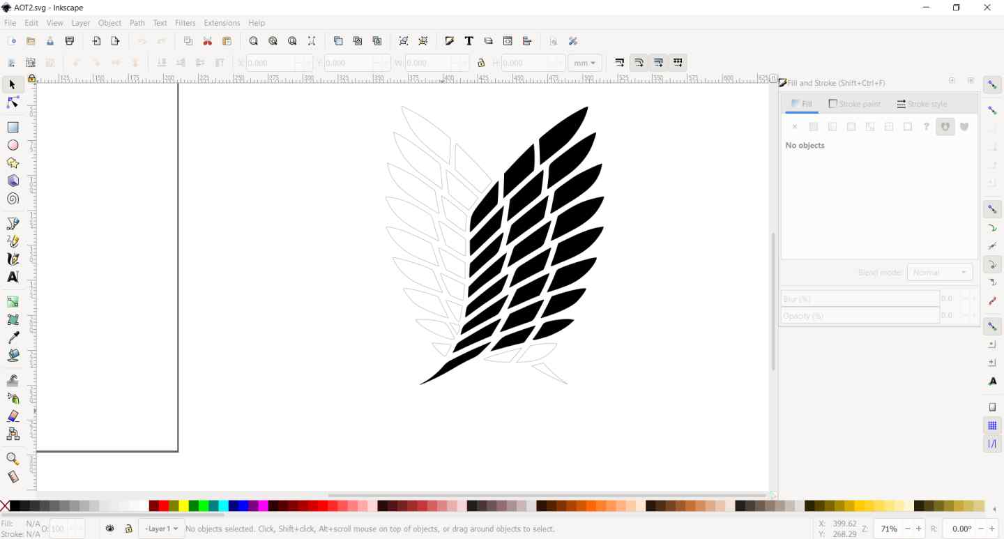
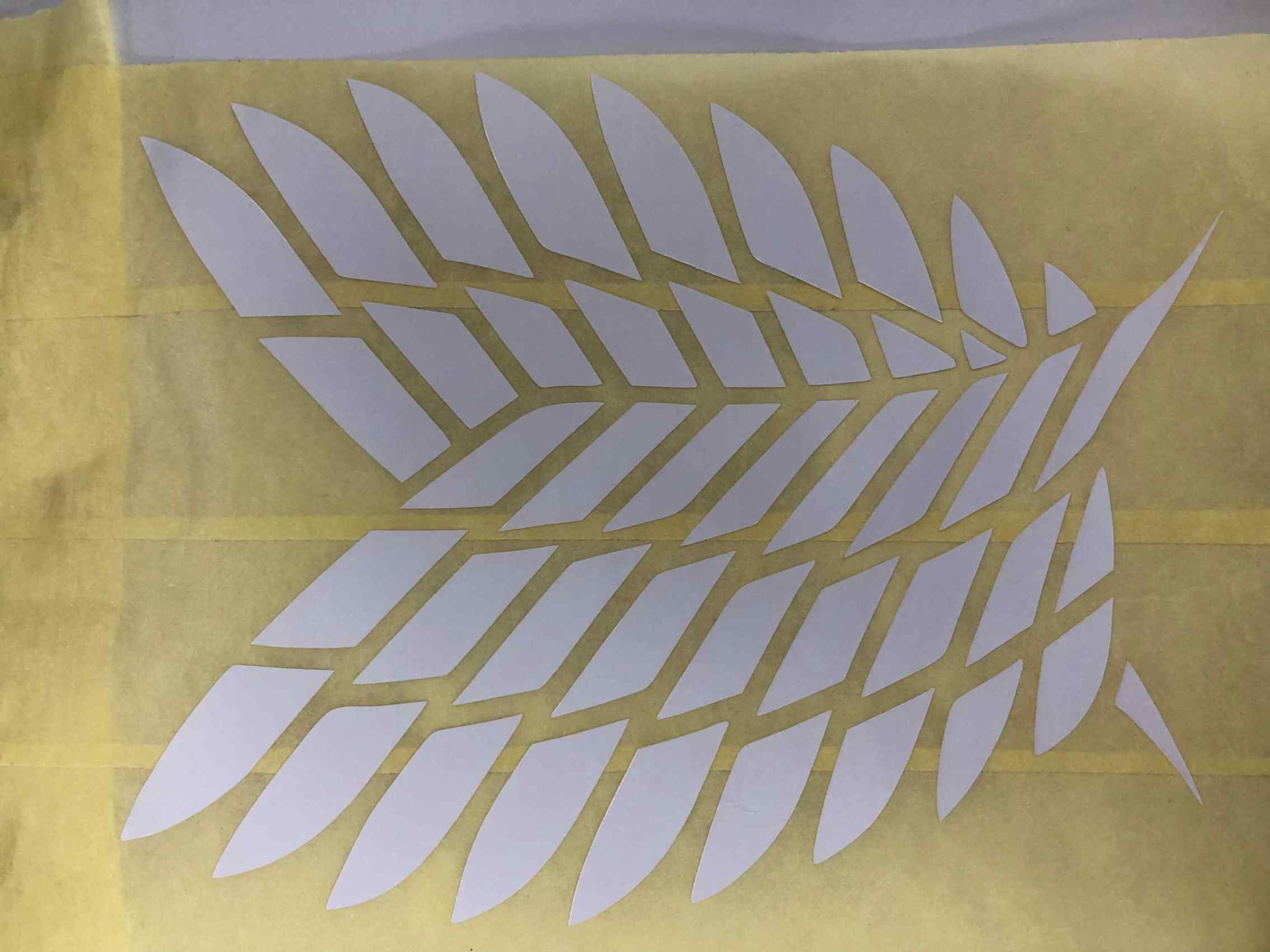
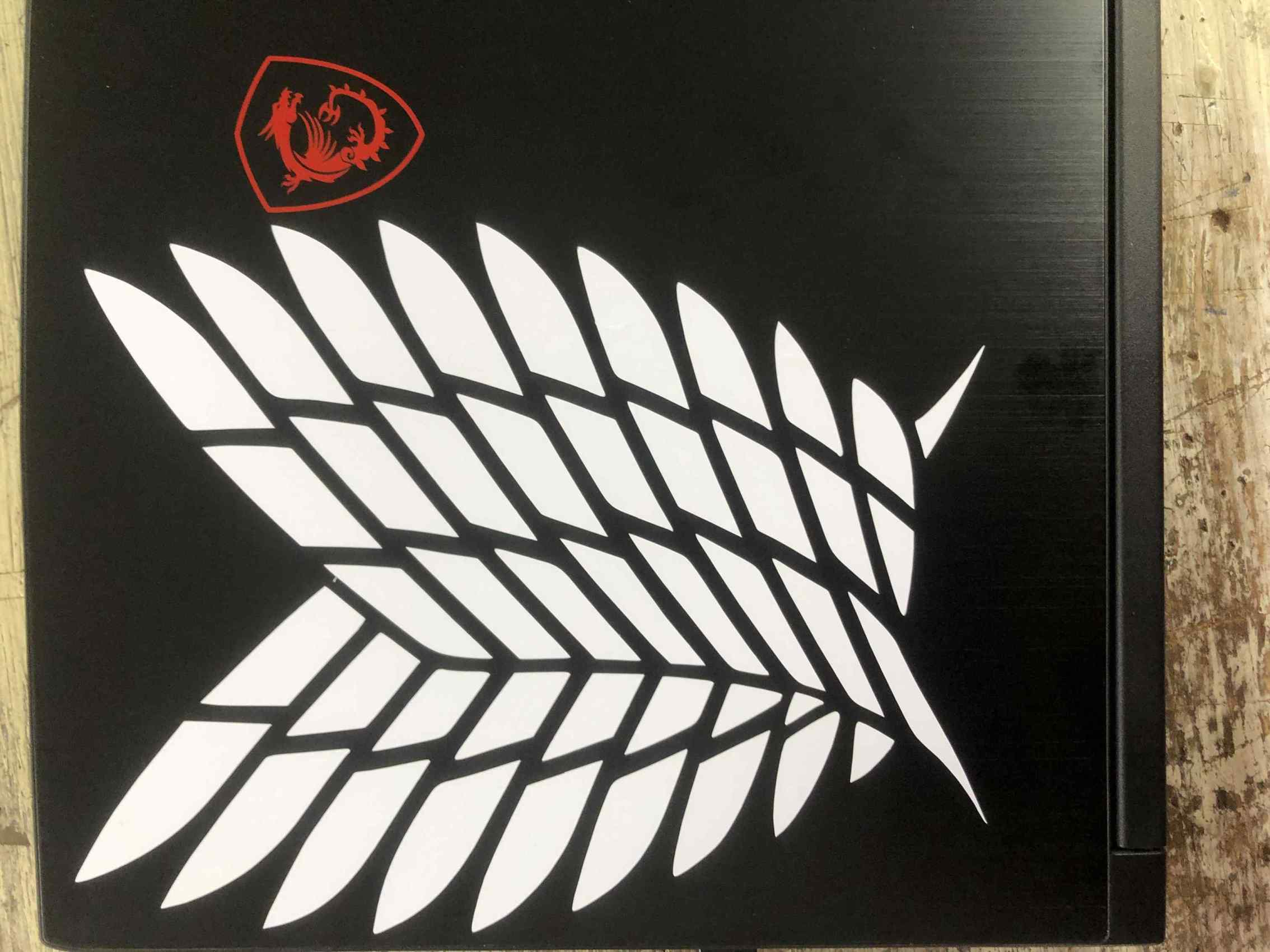
I like Attack on titan anime so I wanted to vinyl cut somthing from it.
I searched online and got a good quality picture of a logo from AOT anime.
When I downloaded it, it had a strange format that I don't recognize and inkscape didn't accept it so I converted it to png using GIMP.
Imported the png to Inkscape and from path I made trace bitmap option.
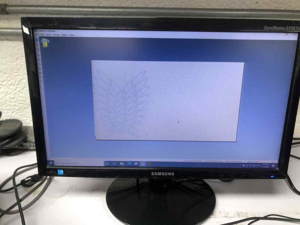
Saved the traced vector as a DXF and opened it with illustrator to save it as ai japanese version, because the cut studio that operates the vinyl cutting machine dosn't accept another vector format.
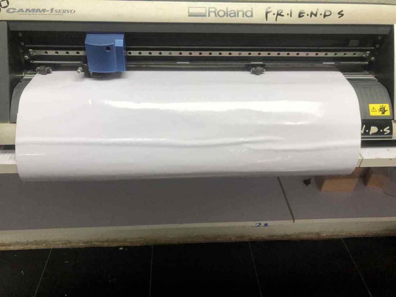
then opened it in cut studio.
I loaded the vinyl piece to the machine and selected piece, the machine calculated its height and width.
Selected cut print from cut studio and from properties I grabbed the sheet dimensions from the machine.
Then print, and the machine started to cut the design.
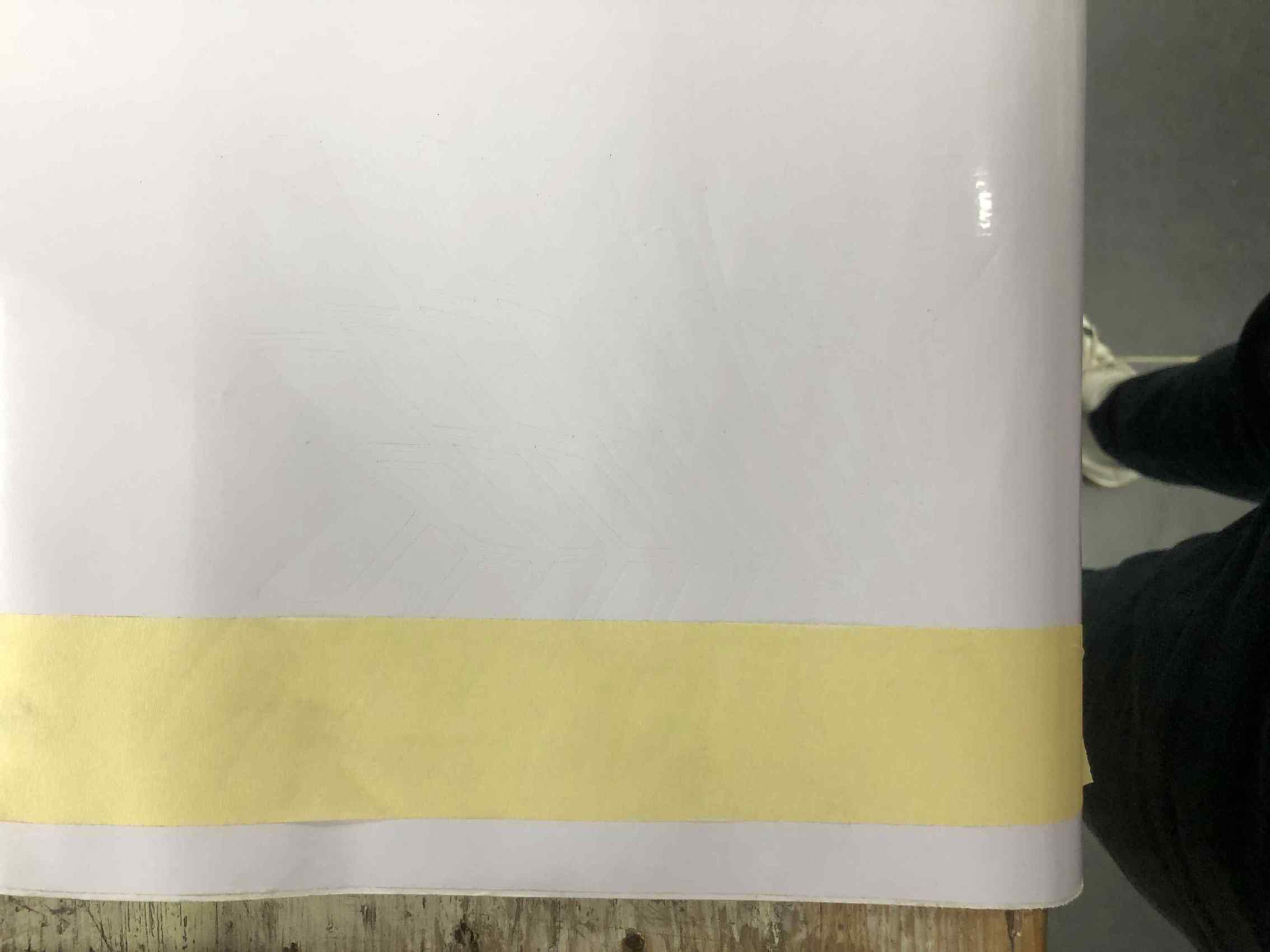
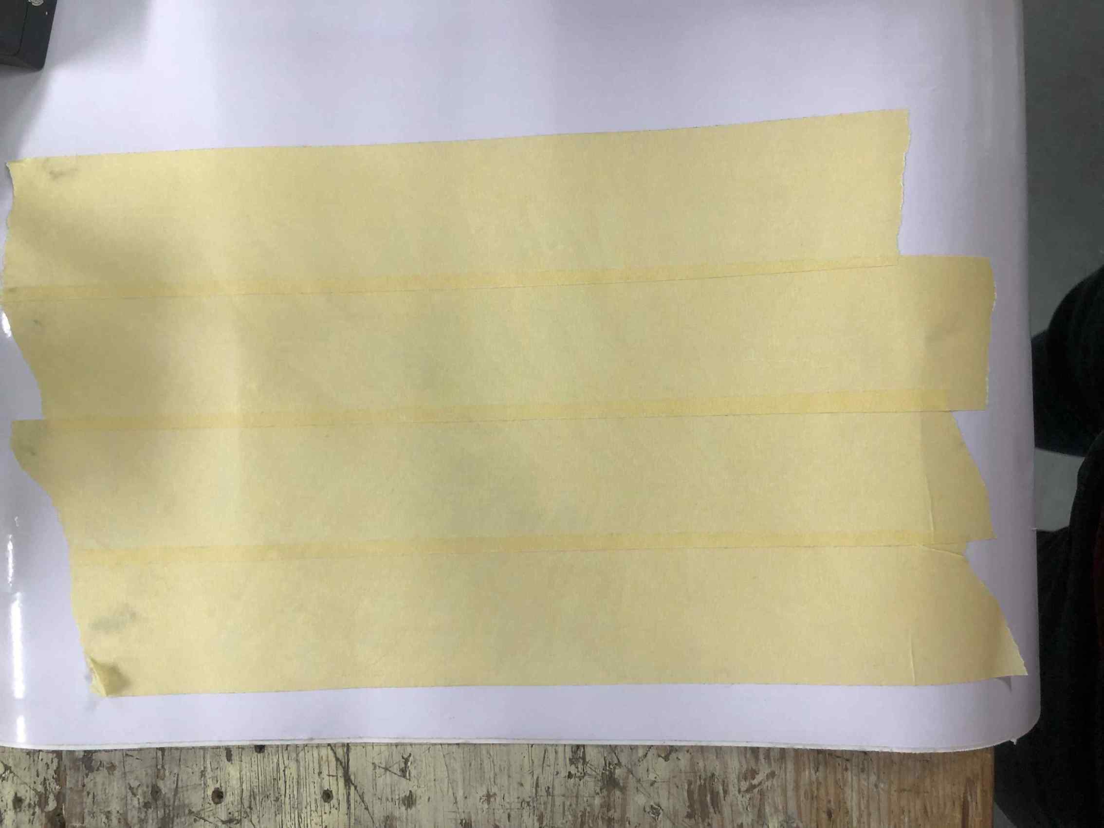
Put a paint tape on the cut vinyl, my design is a bit big so I put multiple paint tape pieces and overlap each one to the previous one.
Slightly remove the paint tape all together and ensure all the cut vinyl pieces stick to the paint tape.
I have put the tape with the vinyl sticked to it on my laptop back and with a card I ensure it sticked in all positions, then removed the tape while getting sure the vinyl is stick to the laptop.
Now I have this nice logo on my laptop back.
once again, Hooray!
Downloads:
Group assignment (my 2 joints, kerf sketch & power and speed sketch)
Construction kit Parts
AoT Logo (Vinyl Cutting)