Computer-Aided Design
Assignment requirements:
- Model (raster, vector, 2D, 3D, render, animate, simulate, ...) a possible final project
- Compress your images and videos
- Post a description with your design files on your class page
Learning outcomes:
- Evaluate and select 2D and 3D software
- Demonstrate and describe processes used in modeling with 2D and 3D software
Assessment criteria
- Modeled experimental objects/part of a possible project in 2D and 3D software
- Shown how you did it with words/images/screenshots
- Included your original design files
Practice
I started the week by deciding what softwares will I use, So I went with GIMP for raster, Inkscape for vector and SOLIDWORKS for 3D.
Raster
So starting with GIMP I went through few videos describing the basics of how to open and what are the available tools then followed this tutorial which was funny, nice and introduced important tools.
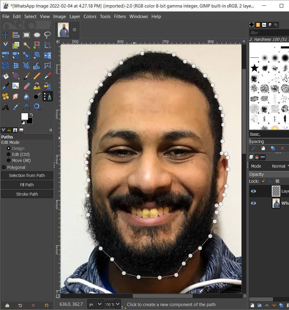
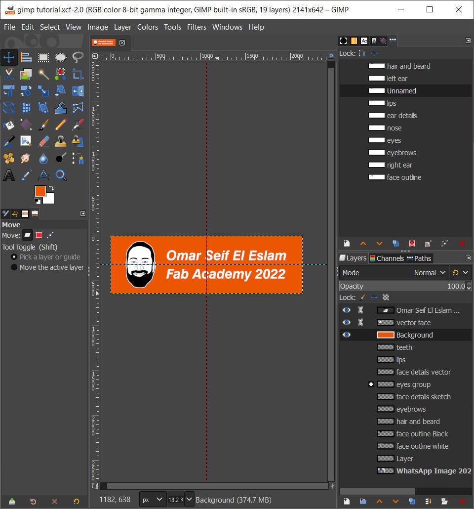

I took a picture of myself and started working on it, I came up with a strange face logo that doesn't look like me but it was nice experince and learned alot through it.
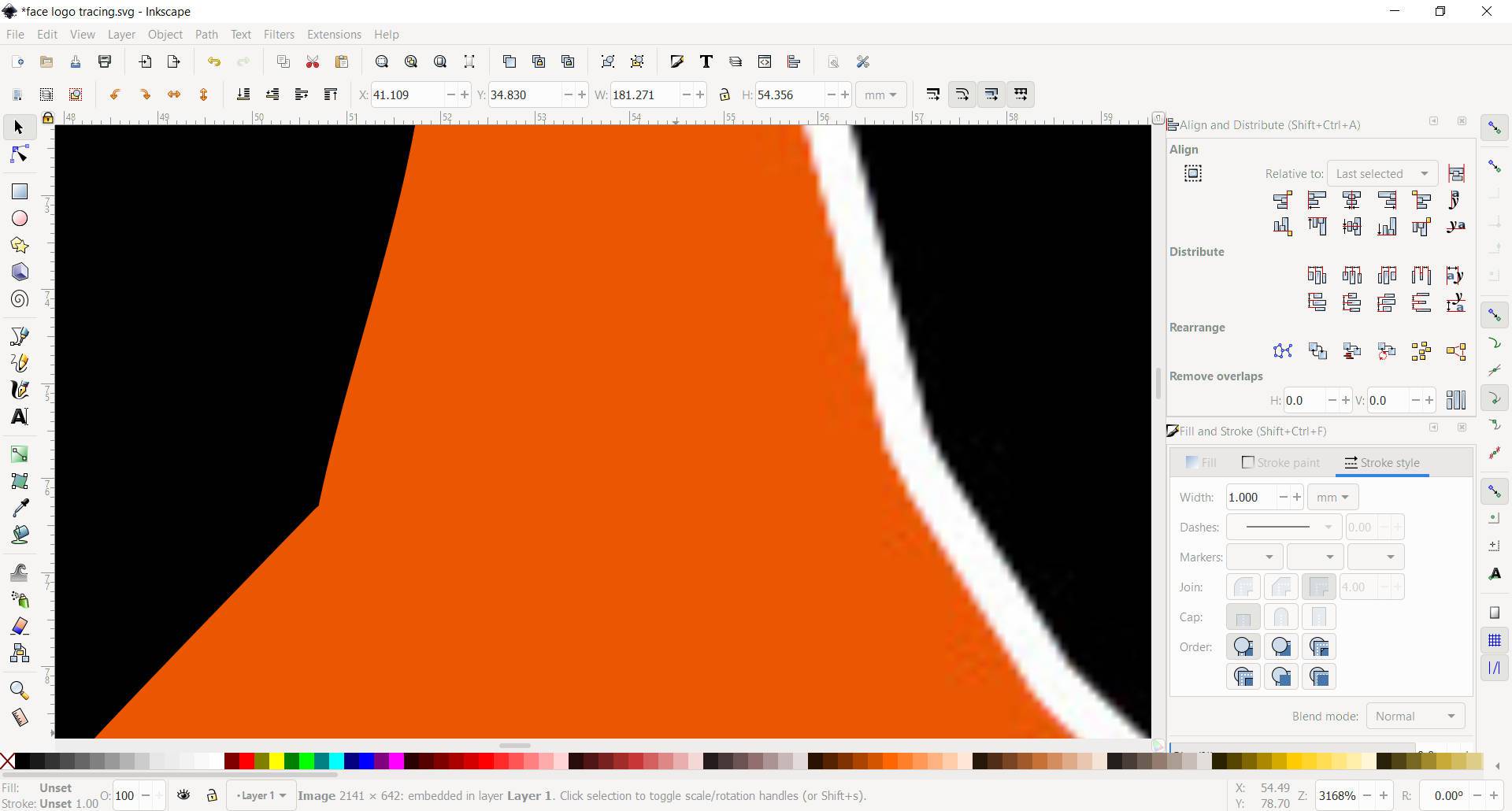
Vector
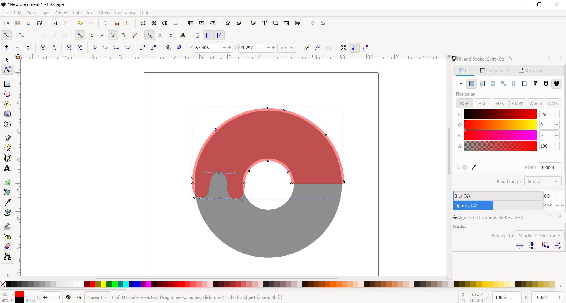
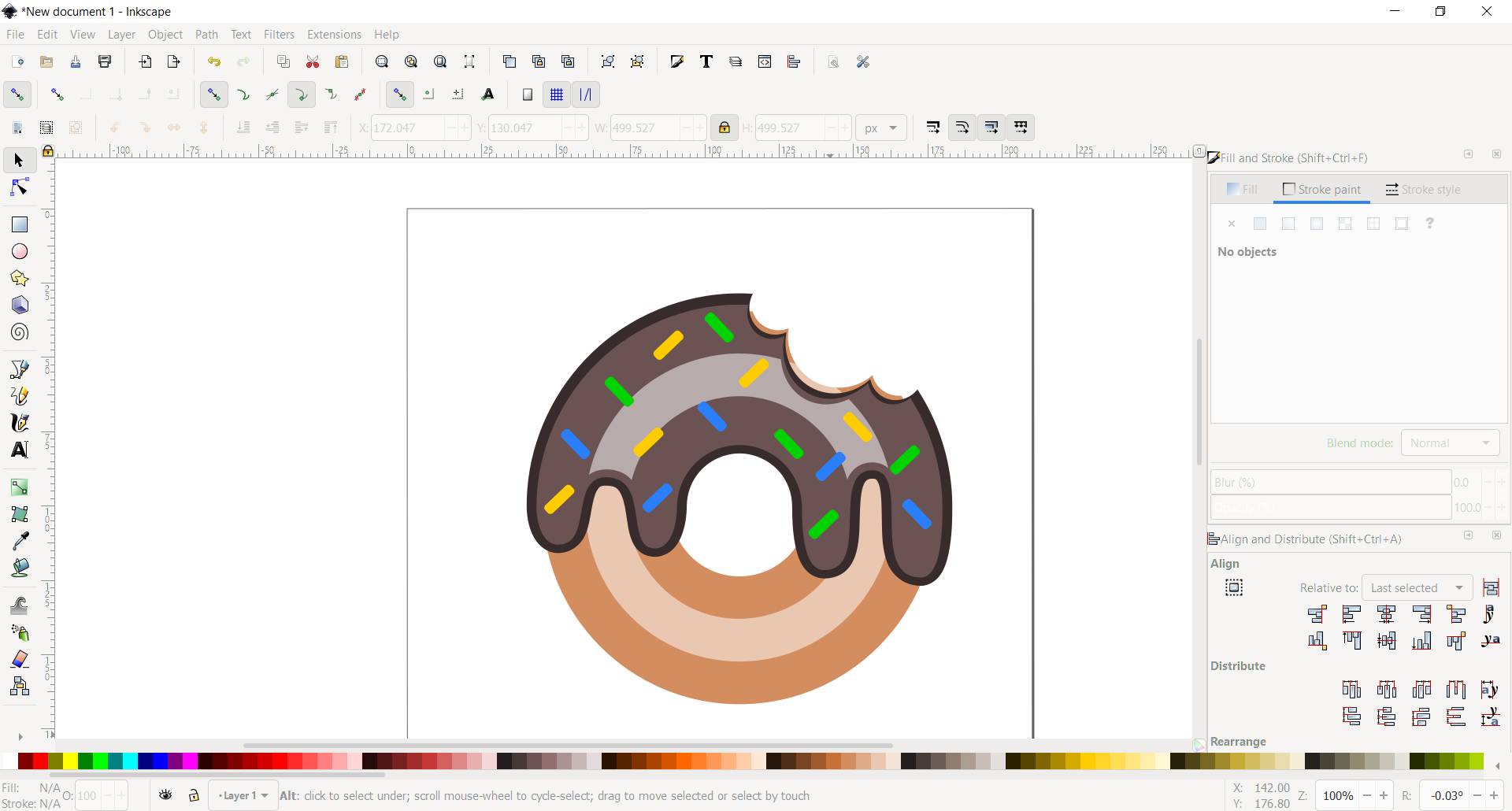
Then went to Inkscape to explore what is vector and do some practices, I went through this tutorial and also took the logo I made in gimp and followed it with path tool to see actually the vector vs raster.
3D
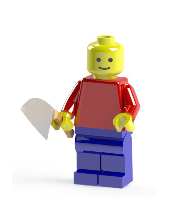
Then I went to SOLIDWORKS to practice the 3D design, creating multiple parts and add them together to build something, So I did a practice through this tutorial and completed the lego man.
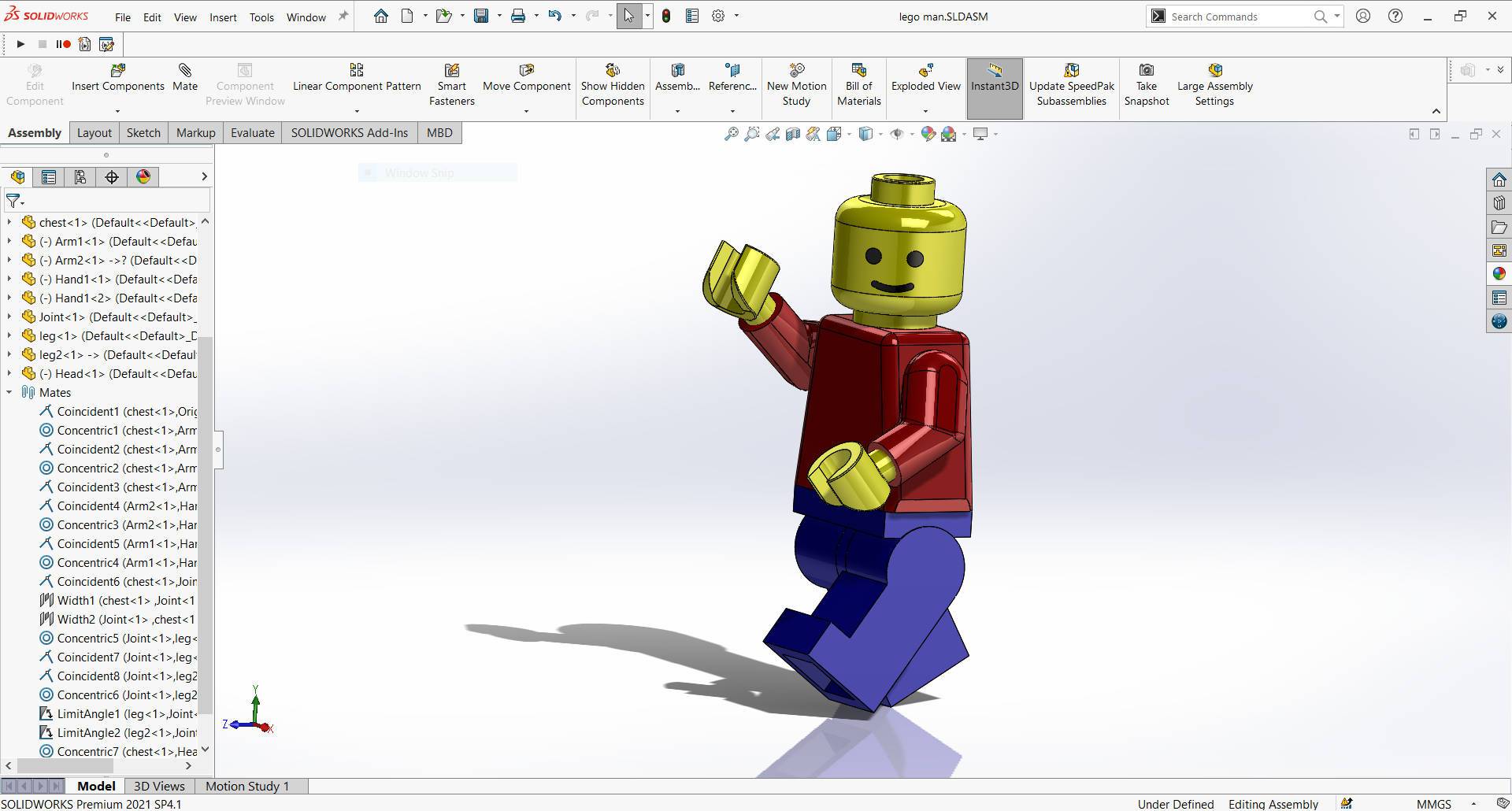
After finishing the lego man the look on his face gave me an impression so I went to grabcad and downloaded a knife to add to the design and rendered it with photoView 360 add-in
Apply
Raster
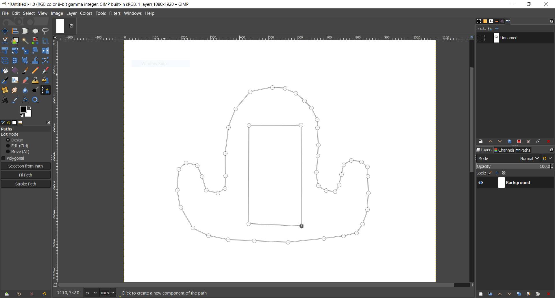
I started to sketch on GIMP what I think my final project will look like.
- Open GIMP, from file > new to start and new sketch.
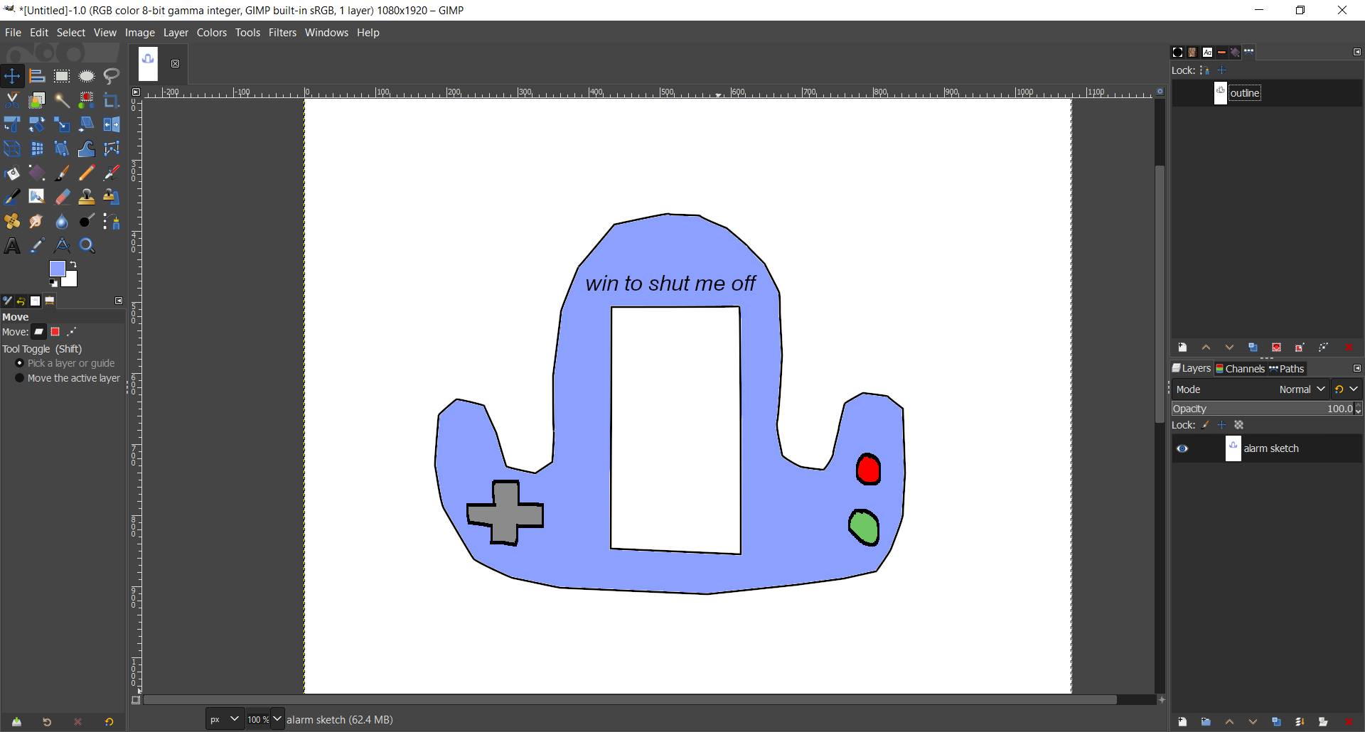
- Used paths tool to define the shape of my project then stroke path.
- Used Paintbrush to draw buttons and Text tool.
- Used Bucket fill tool to fill colors inside each closed region.
Vector
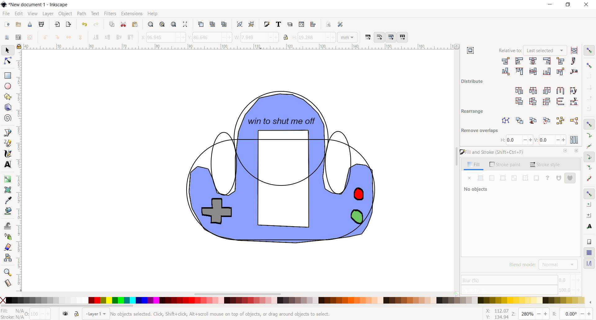
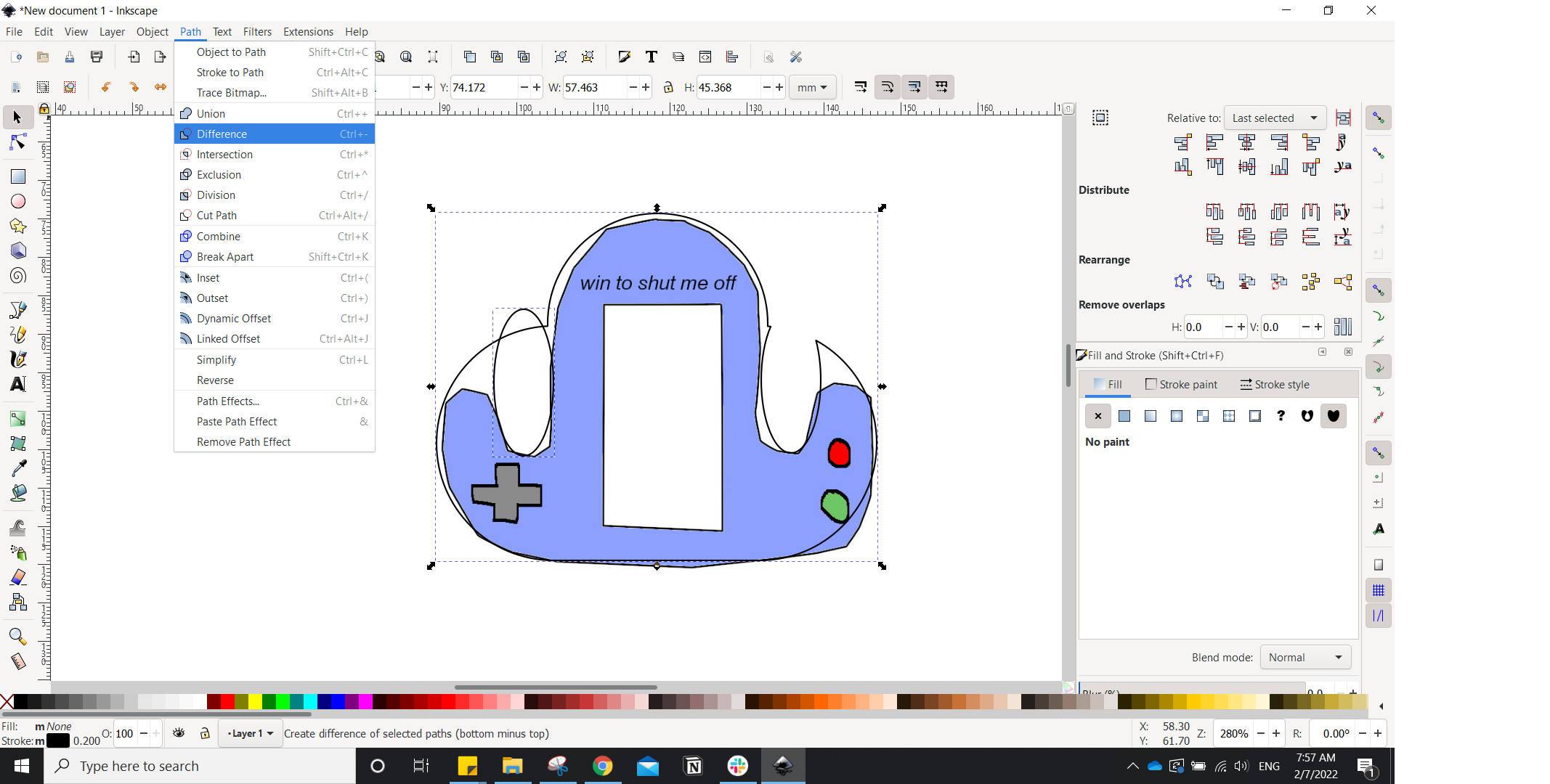
To make a vector sketch I went to inkscape and sketched the final project again.
- Open Inkscape and imported the sketch I have made on GIMP to be as a reference.
- Created circules and rectangle to form the shape.
- Used lower/raise selection one step and Path > union/differece to maintain the outline and remove inside lines .
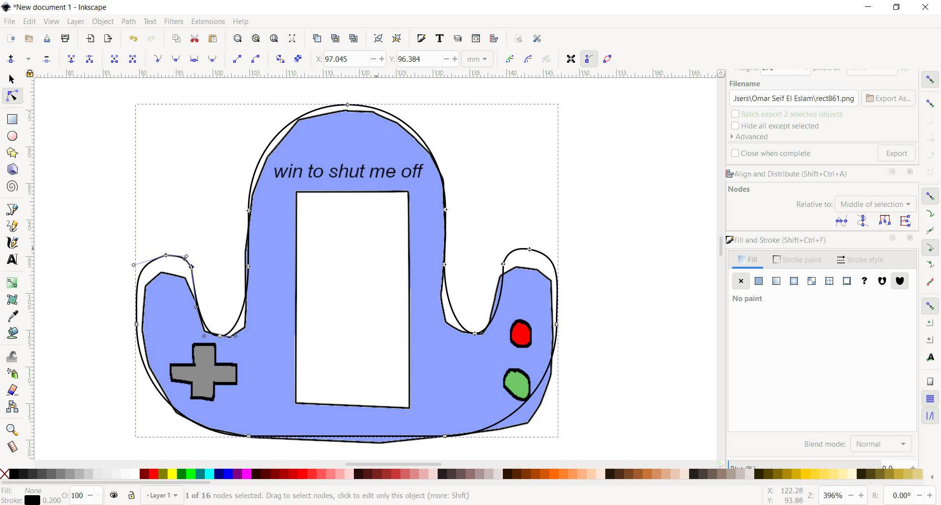
- Used edit path nodes to smooth the edges.
- Then added buttons with circles and rectangles and used fill bounded area tool to add colors.

3D design
I was thinking what should I design in 3D to show movement, so I didn't design the final project and went with something else, and because I love gyroscope I decided to design one.
- Opened SOLIDWORKS File > New > New part.
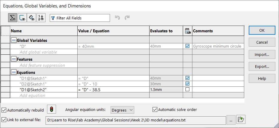
- I wanted to use equation to try to make a parametric design so from Tools > Equations I added a global variable and exported the equation file to import it in every part in this design to use the same variable.
- Main feature I used are Extruded Boss, Extruded Cut, Revolved Boss, Fillet and Mirror.
- I started designing the gyroscope with 5 parts.
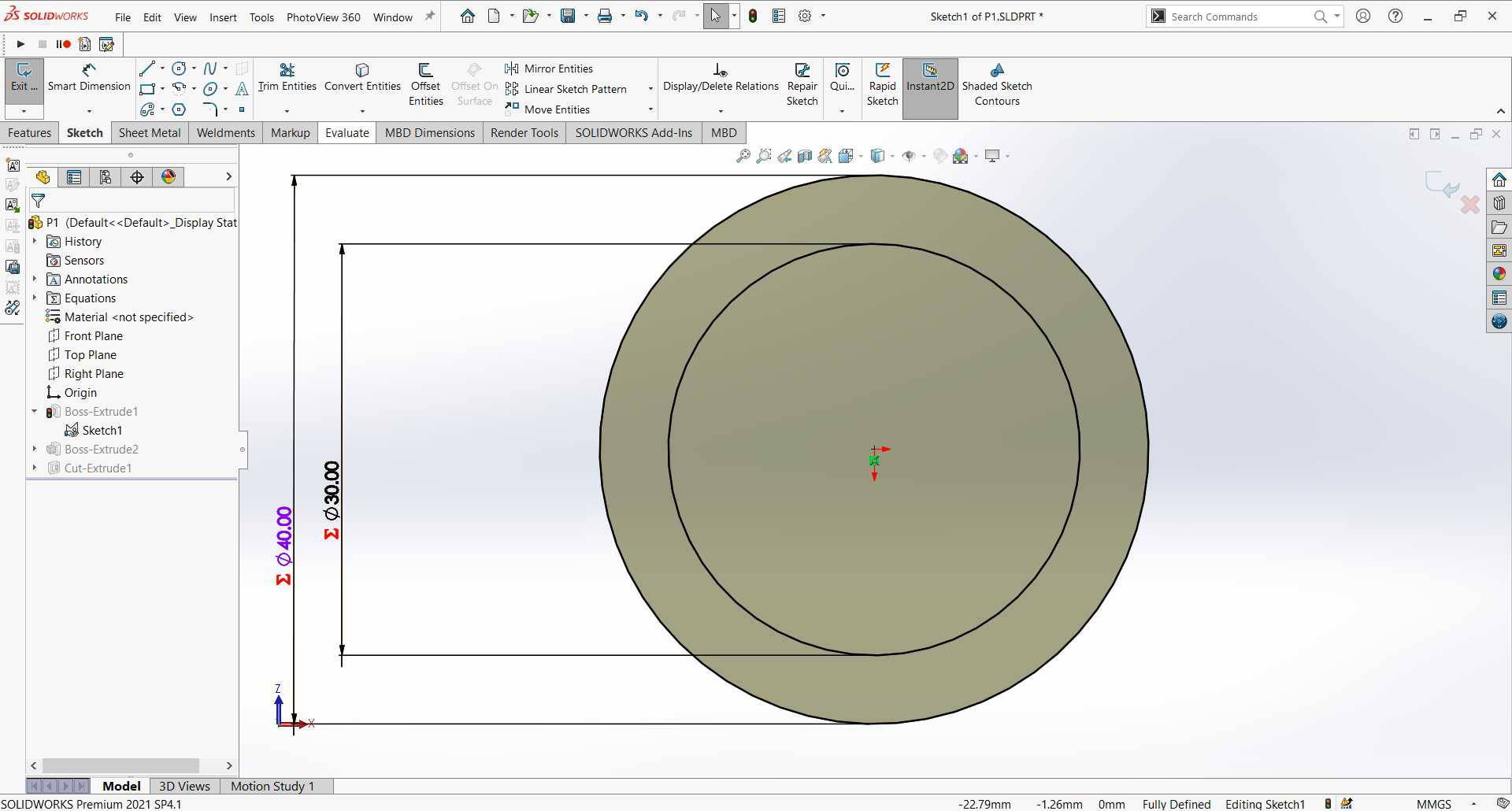
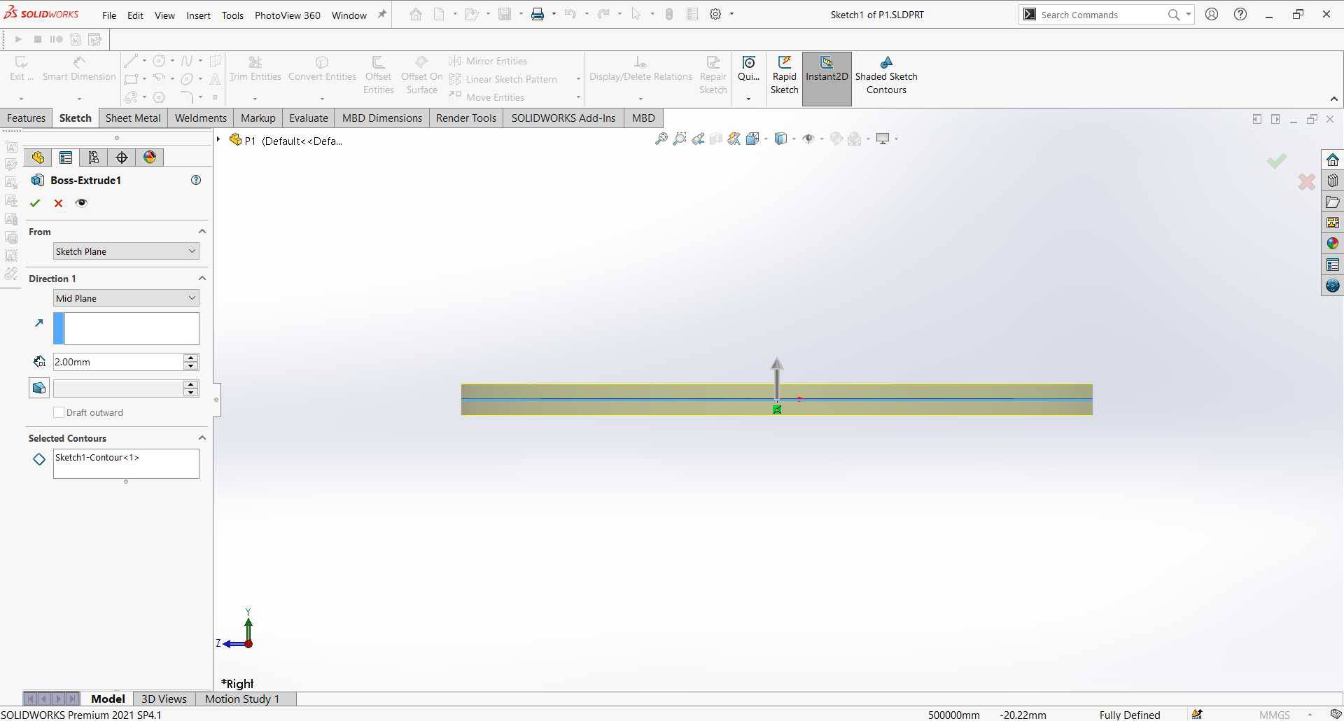
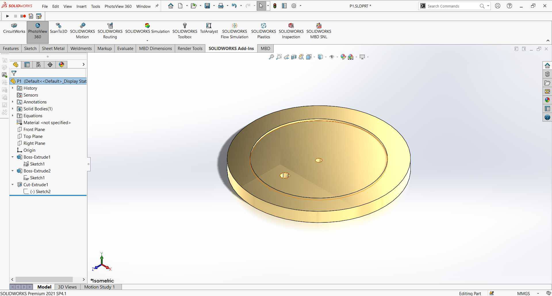
- Part 1: inner desk that rotates to maintain the balance.
- Selected a plane to sketch on and sketched to circles to make a level in the desk, adding dimensions with smart dimension tool.
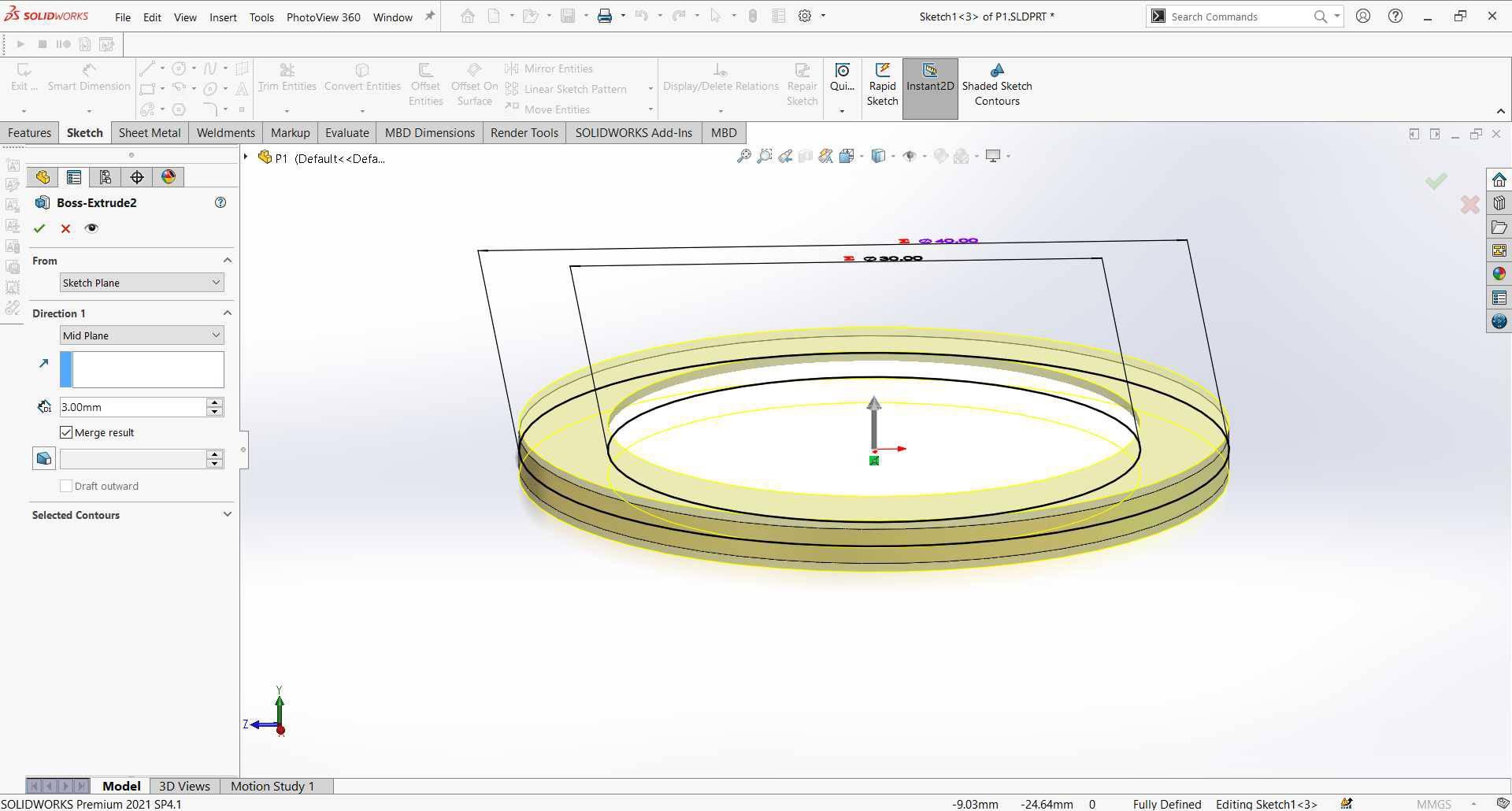
- Extruded the whole desk by selecting the outer circle 3mm and then the region between the 2 circles to make the 2nd level in the desk.
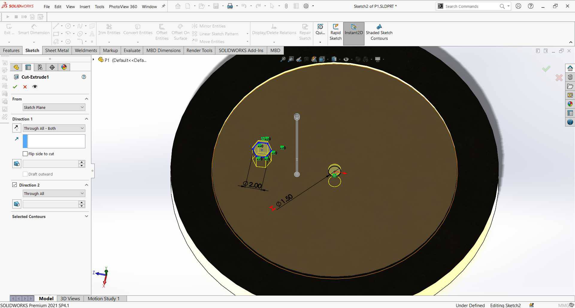
- Selected the desk plane and sketched on it, added a circle in the center to fit in the rod in part 2 and any shape at any place to easily indicate when a motion is added
- from left menu clicked on appearance, then opened appearance liberary to choose what I like.
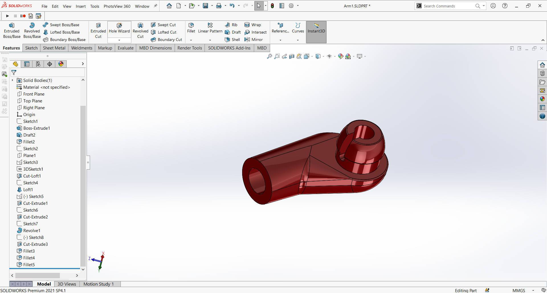
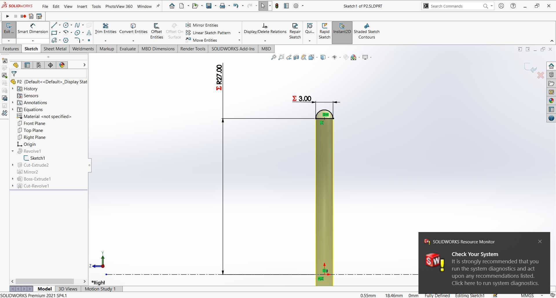
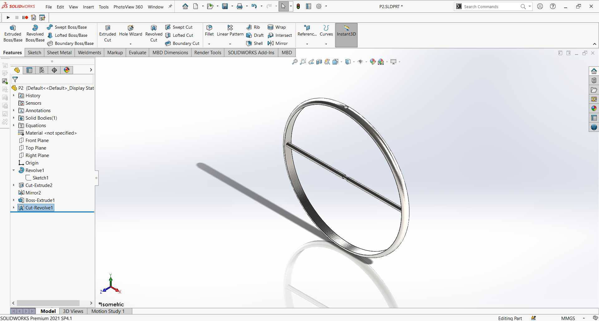
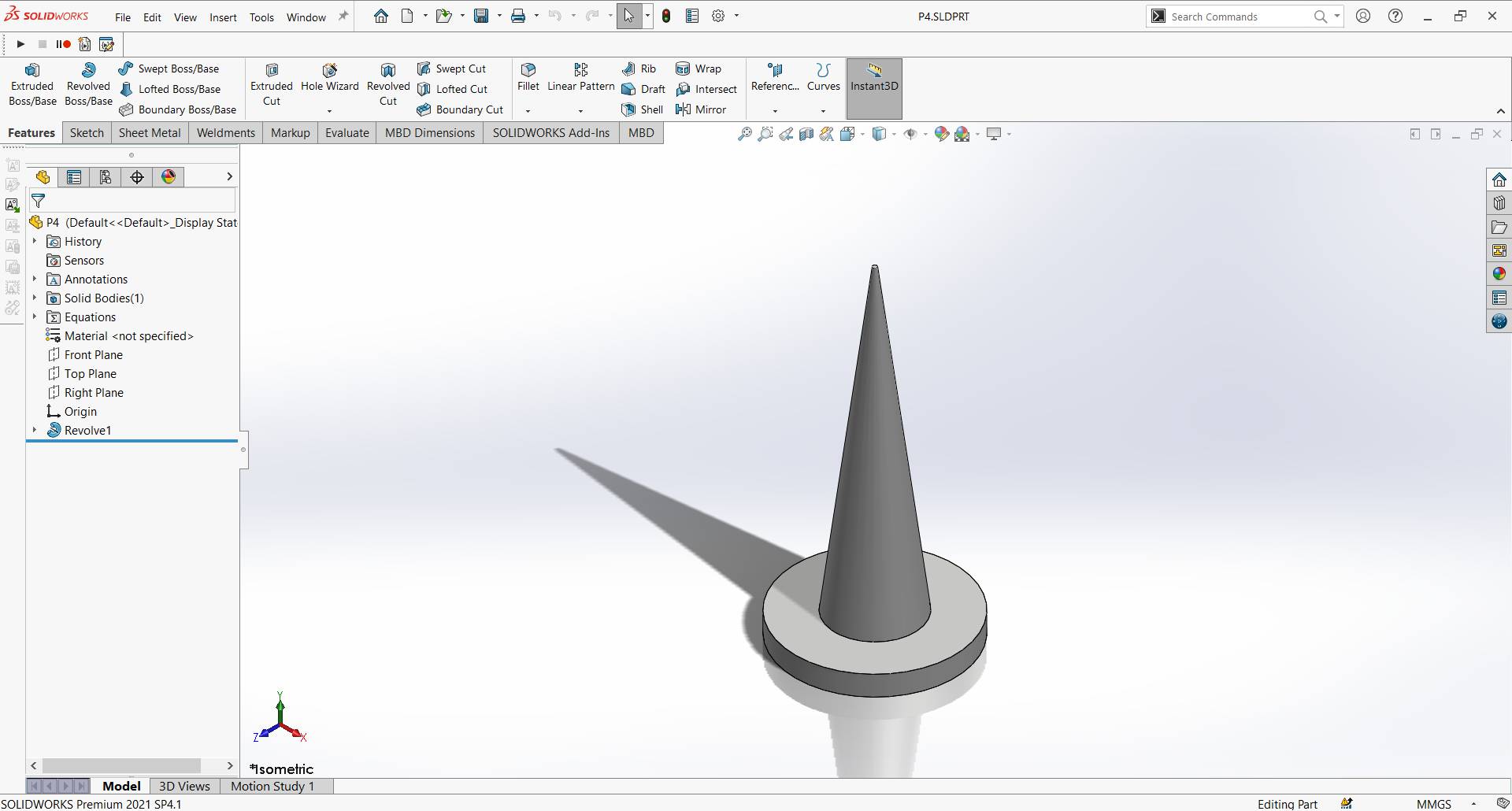
- Part 2: Created another Part that will have the rod that holds the inner rotating desk.
- This time I choose to use the Revolved feature, so I selected a plane to sketch and with line and circle sketched the cross section of the ring.
-
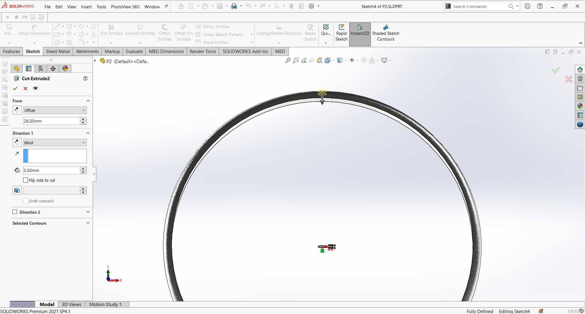
Then on a perpendicular plane on the ring (same plane for the revolved sketch), I sketch a circule in the center and used it to make circular cuts on the outer surface of the ring where it will be attached to the bigger ring and used mirror to have the cut in both directions.
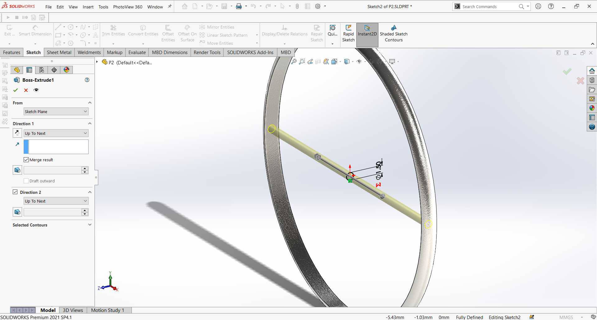
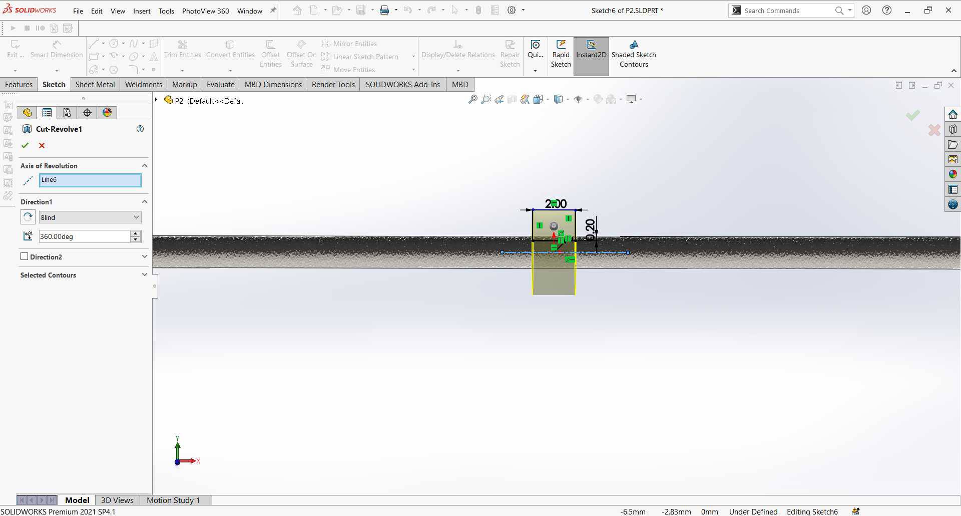
and another circular perpendicular on this circle but this time to extrude it and create the rod that will hold the desk. - Sketch a rectangle to use it to cut revolve the rod to create a solt to hold the desk from going up and down, then adding appearance.
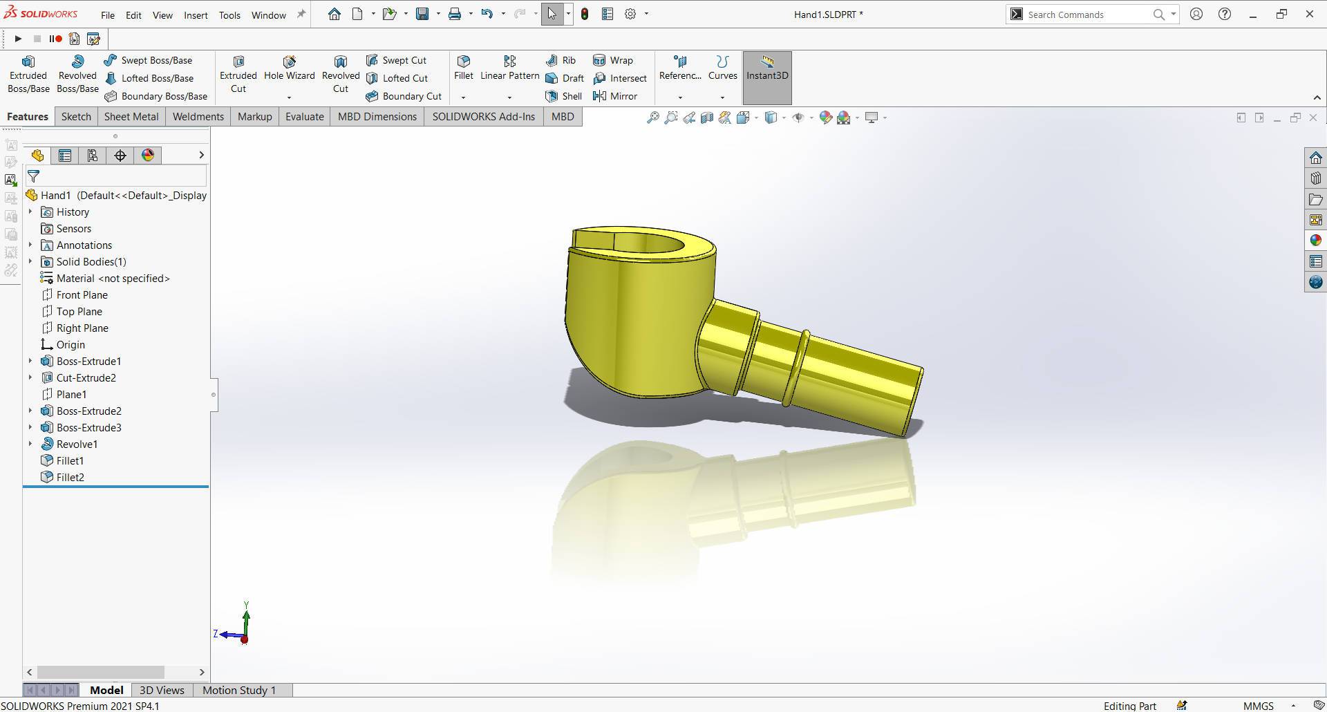
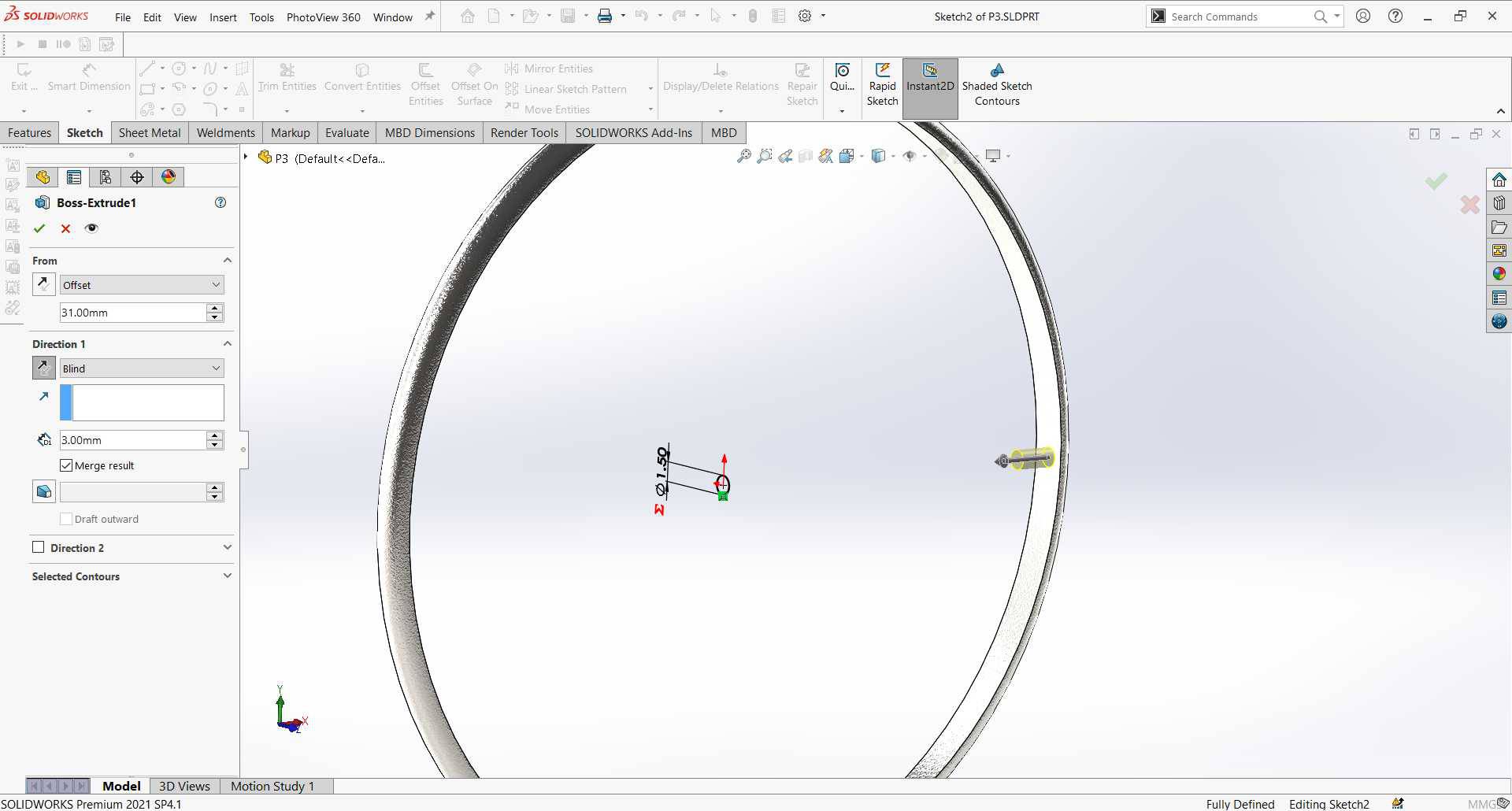
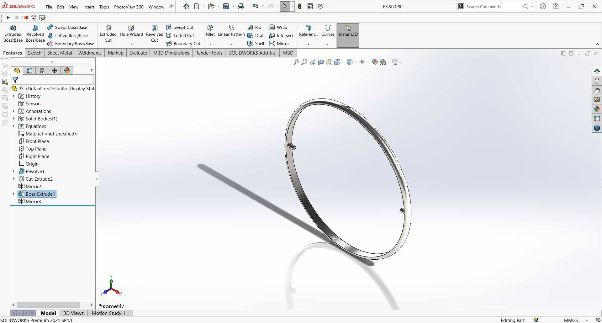
- Part 3 & 4: Part 3 & 4 are the same but with different diameters and the differece between both of them and part 2 that they don't have the rod but instead the have a small guides to be attached to the smaller ring.
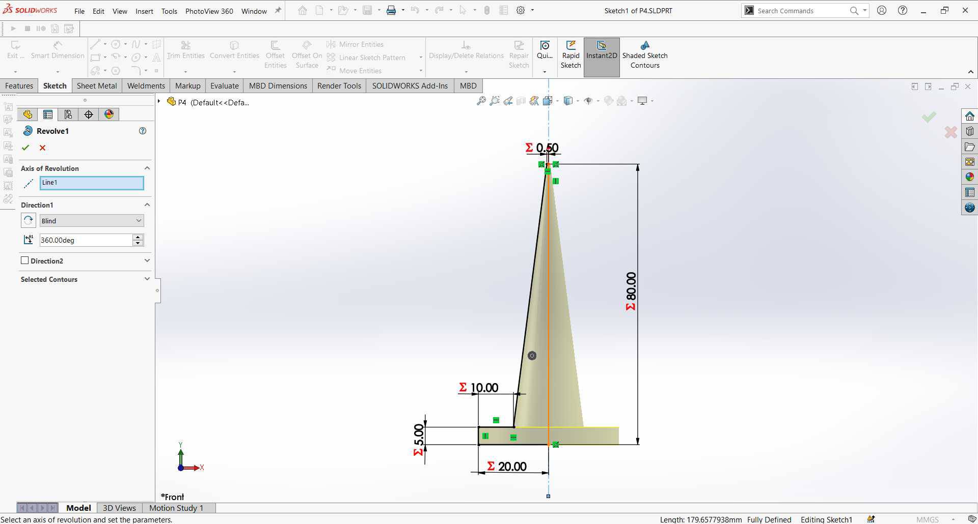
- Part 5: This will be the holder of the gyroscope, I selected a plane and again sketched the profile to revolve it and have the full stand at once.

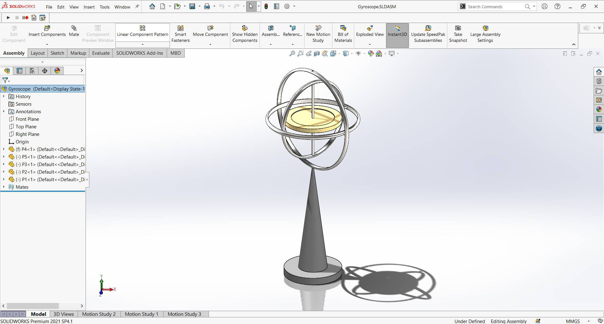
Assembly
- Opened SOLIDWORKS File > New > New assembly.
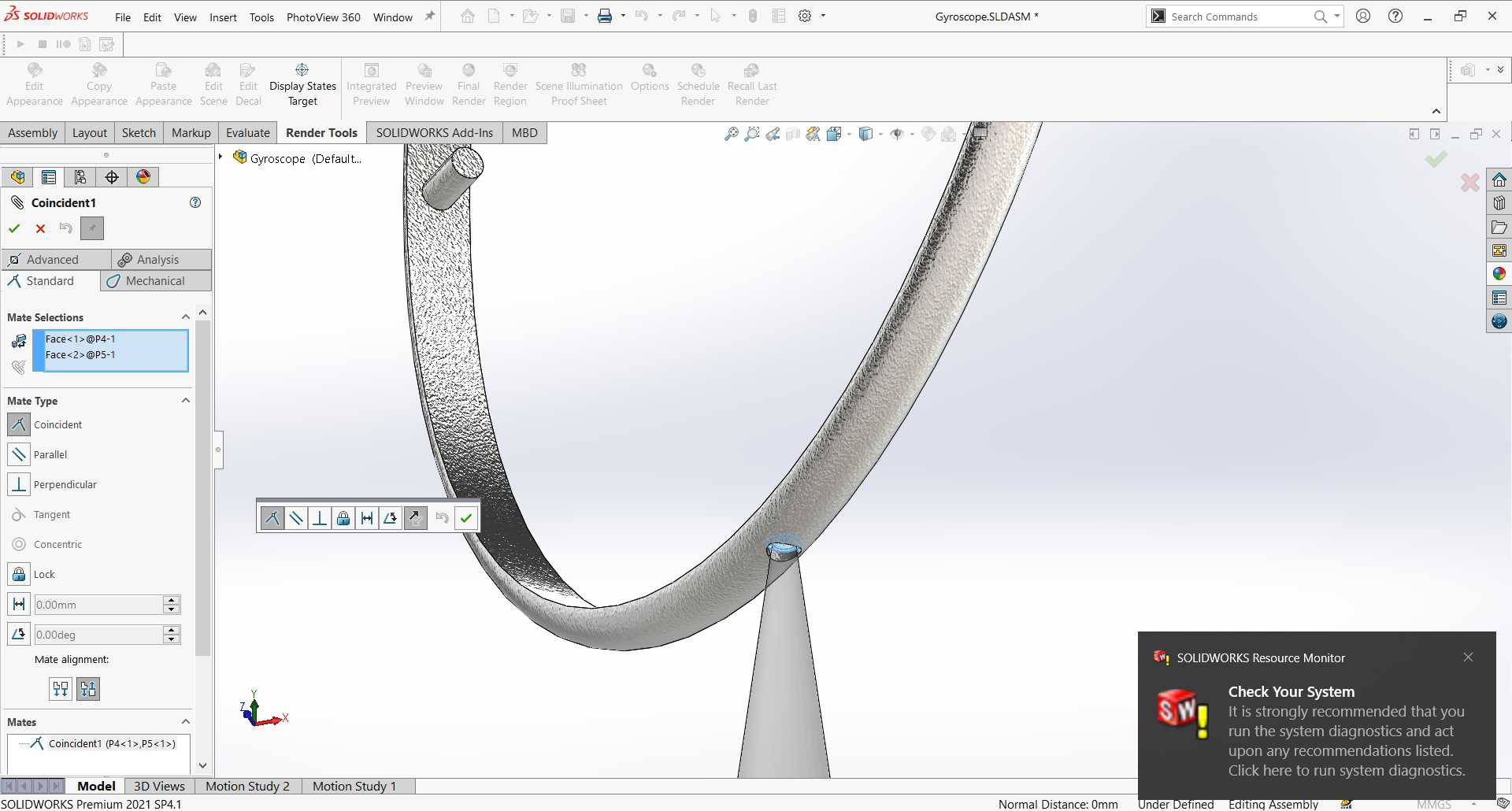
-
Insert components, First I inserted Part 5 then part 4 and used 2 mated with them, first mate is Coincident for the top of the stand and the inside face of the outer cut from the ring and that means they will be attached to each others.
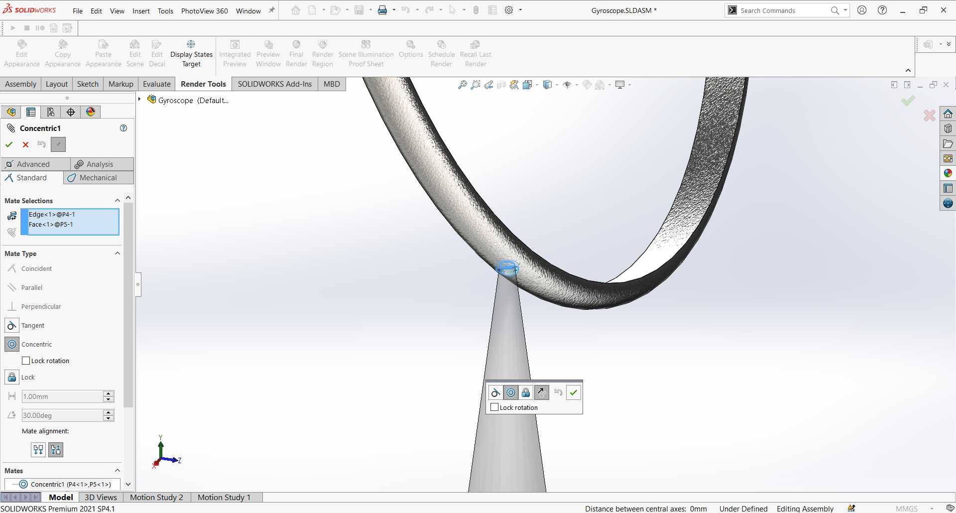
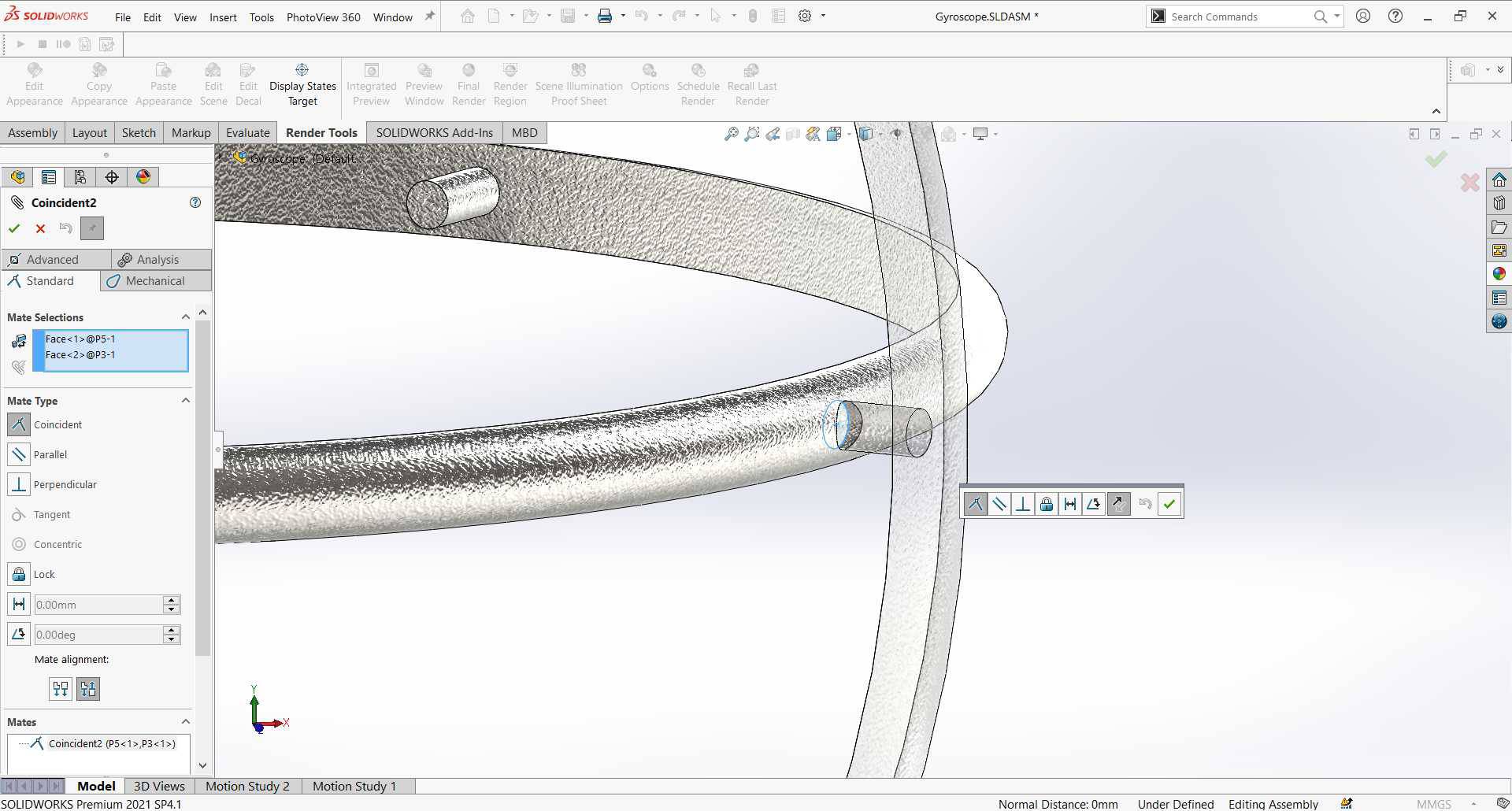
2nd mate is Concentric for the edge of the stand top and the inner cylinder surface of the ring outer cut and that means they will maintain the same center axis and can freely revolve around it. - Insert part 3 and do the same 2 mates but with the pin of part 4, Coincident and Concentric.
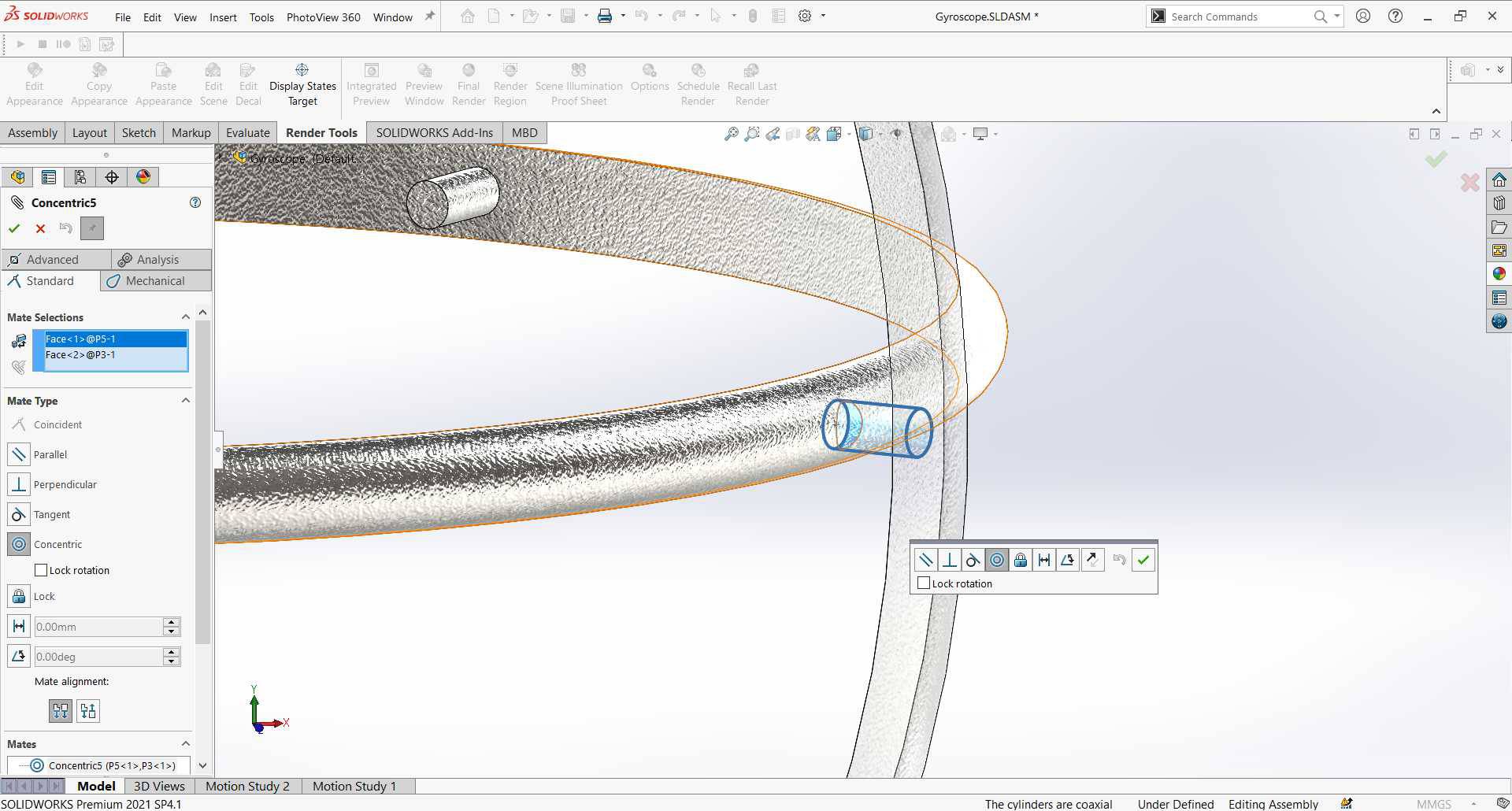
- Insert part 2 and do the same 2 mates but with the pin of part 3, Coincident and Concentric.
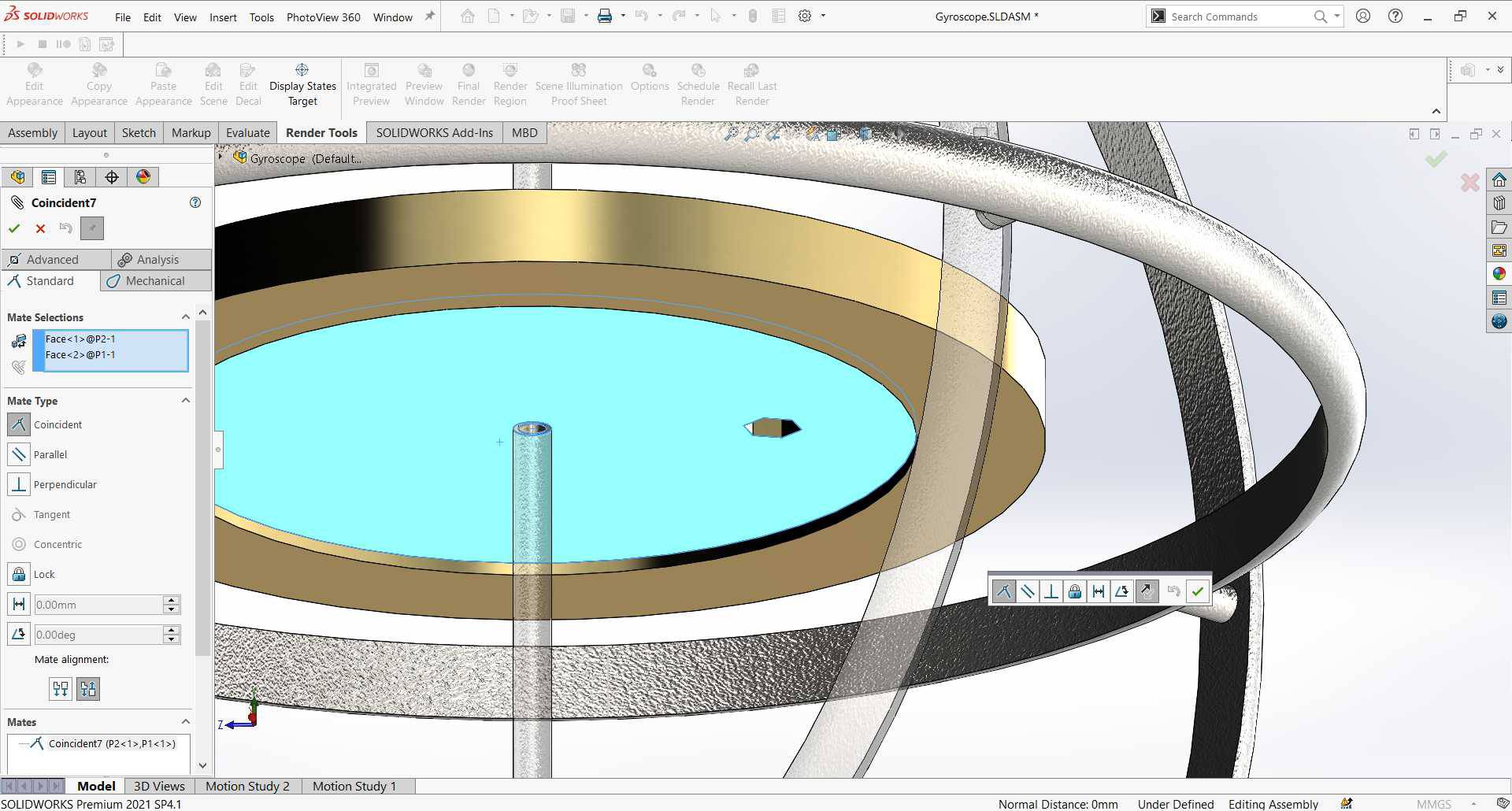
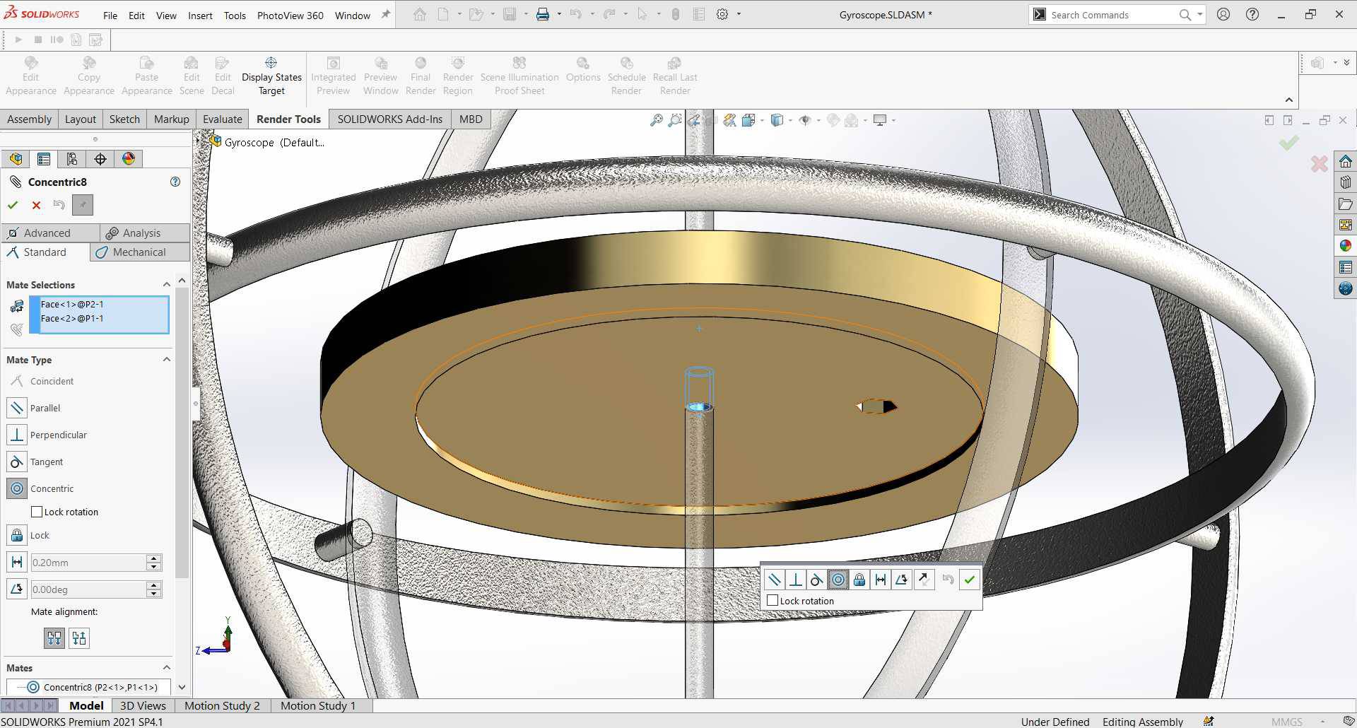
- Insert part 1 and do the same 2 mates but this time the Coincident mate will be between the desk face and the flat face of the rod center slot and the Concentric mate between the rod radial face and the inner hole of the desk radial face.
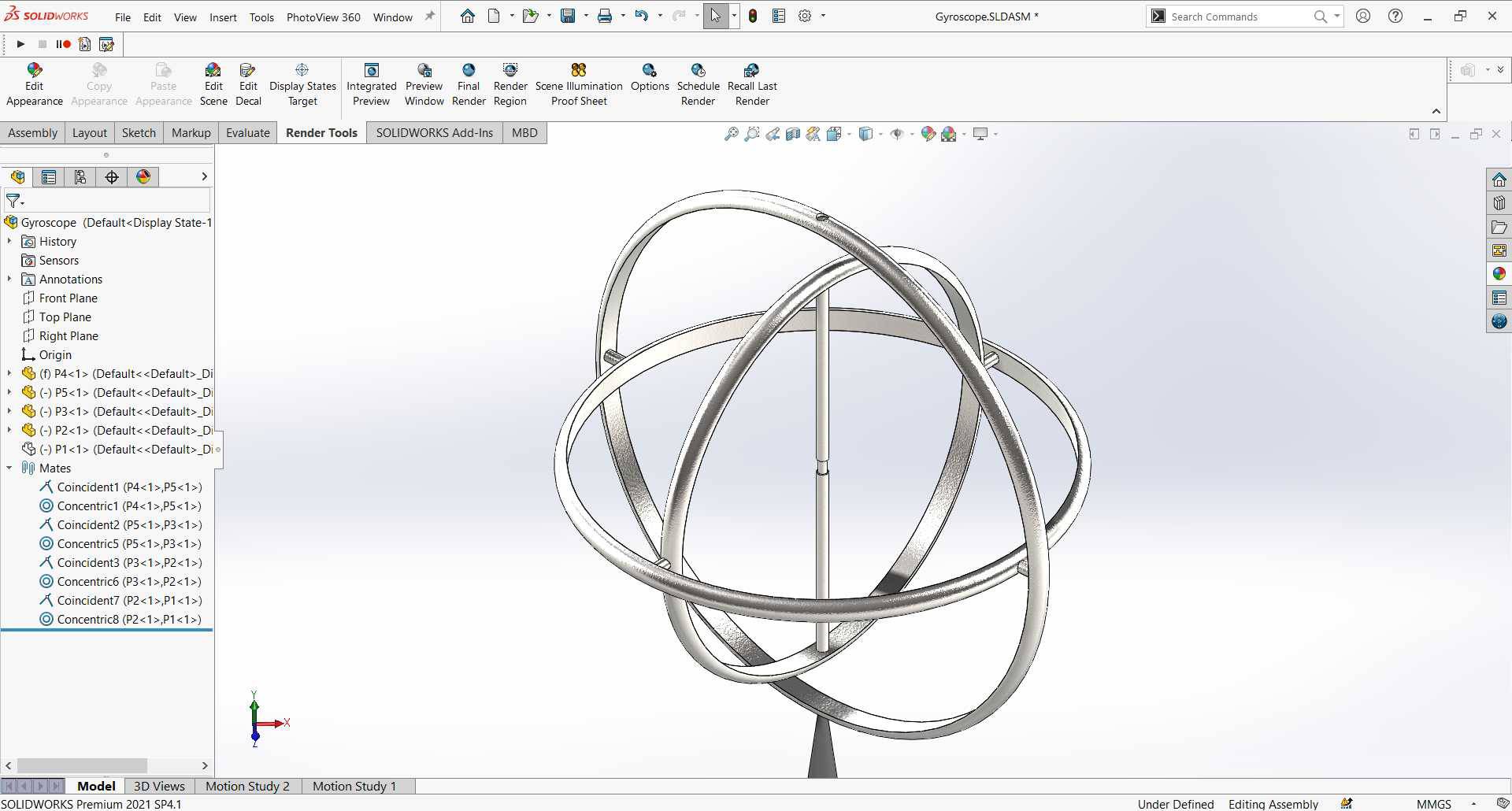
- Now we have a fully assembled gyroscope ready for render and motion.
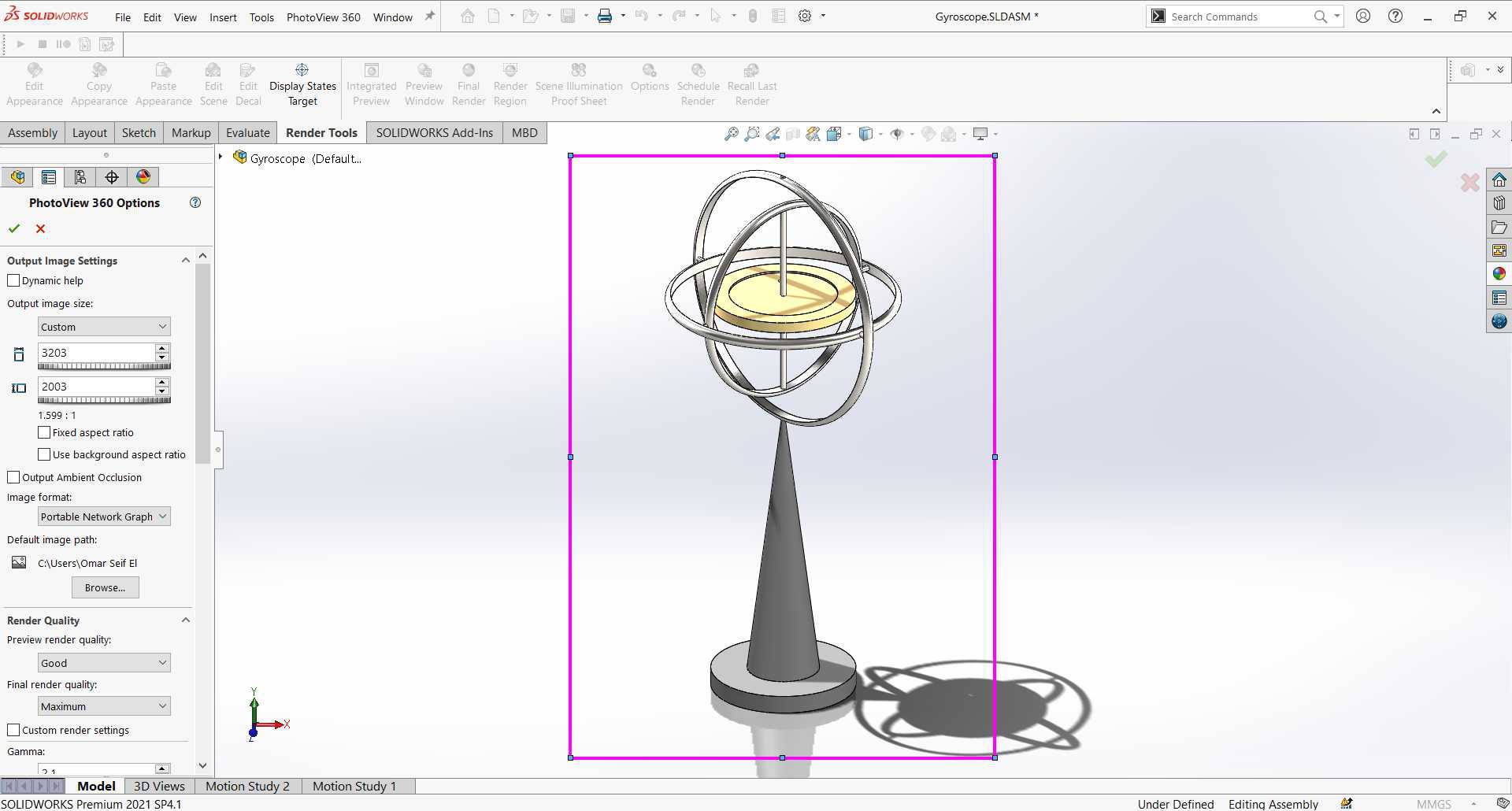
Rendering
-
From SOLIDWORKS Add-Ins click on photoView 360 it will add a new tap Render Tools.
first thing go to render region and specify the region you want to render then go to render options and set the image size you need.
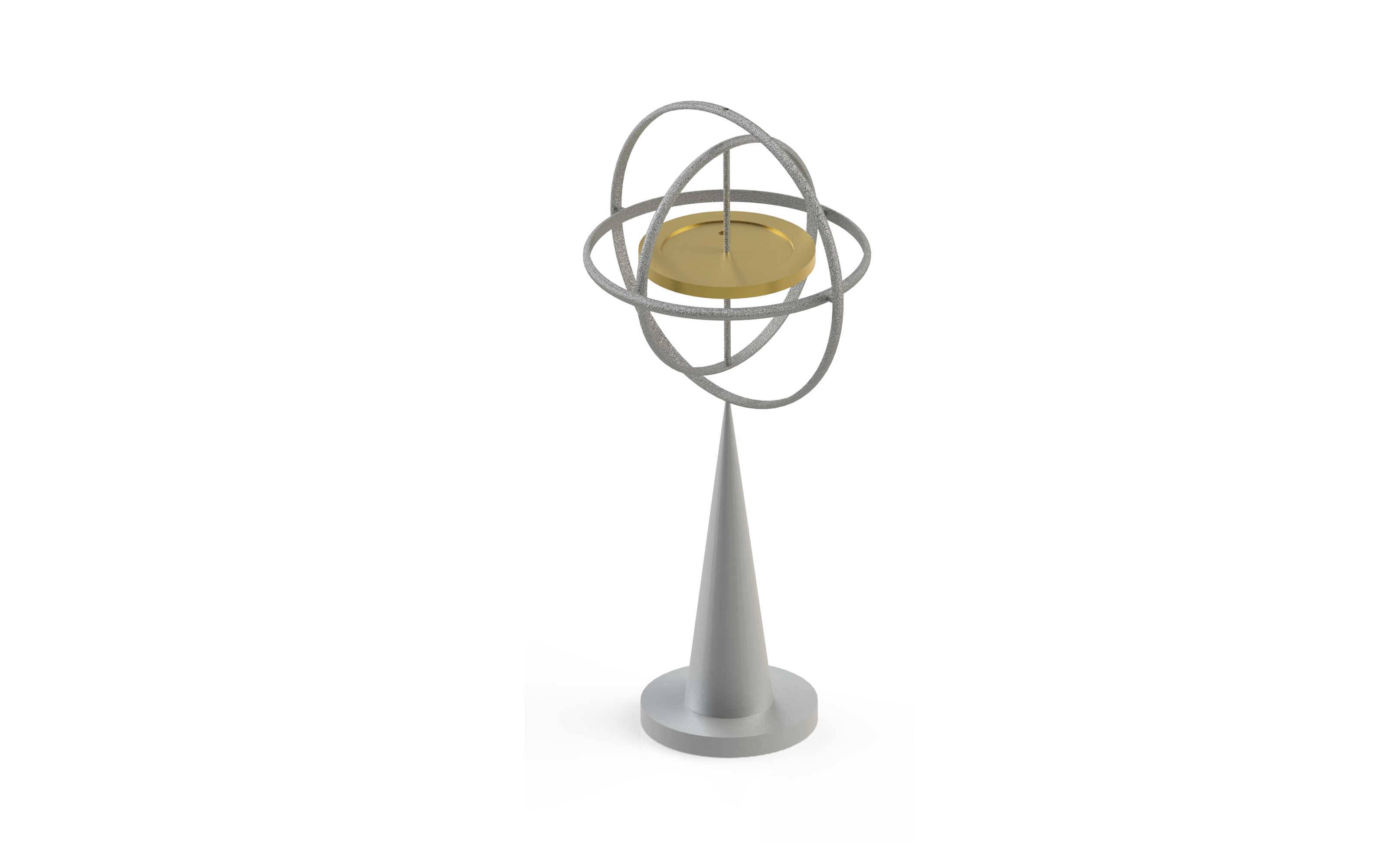
Then Click on Final Render a pop up will ask you if you want to add camera or prespective view and I usually add camera it's an enhancement of the render region option that you can edit focus and so on, then wait it to finish then save the picture, If you are not sure about the image size of the render region or Camera you have set you can click on Preview Window only for faster preview of the output then Final when you're sure.
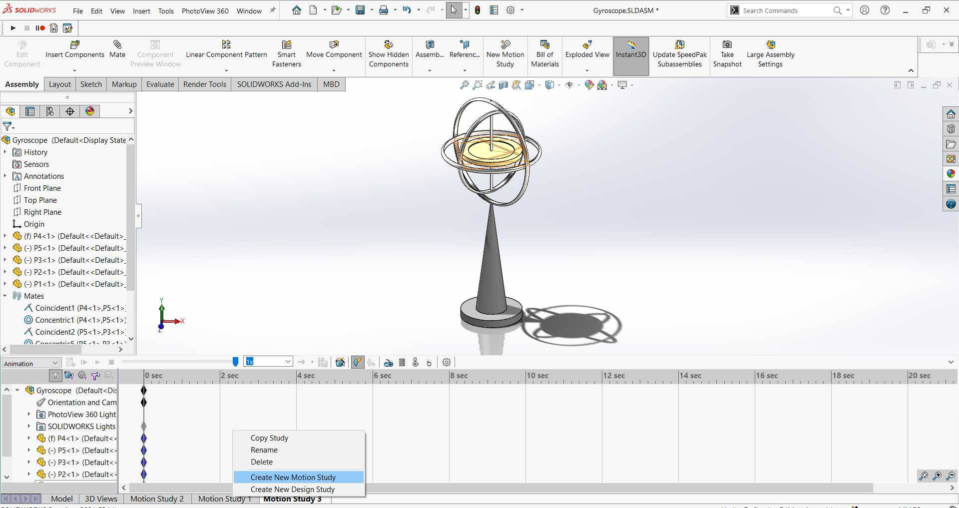
Animation & Simulation
I wanted to do Animation and Simulation using SOLIDWORKS and I did, I watched this Video and it was very helpful.
-
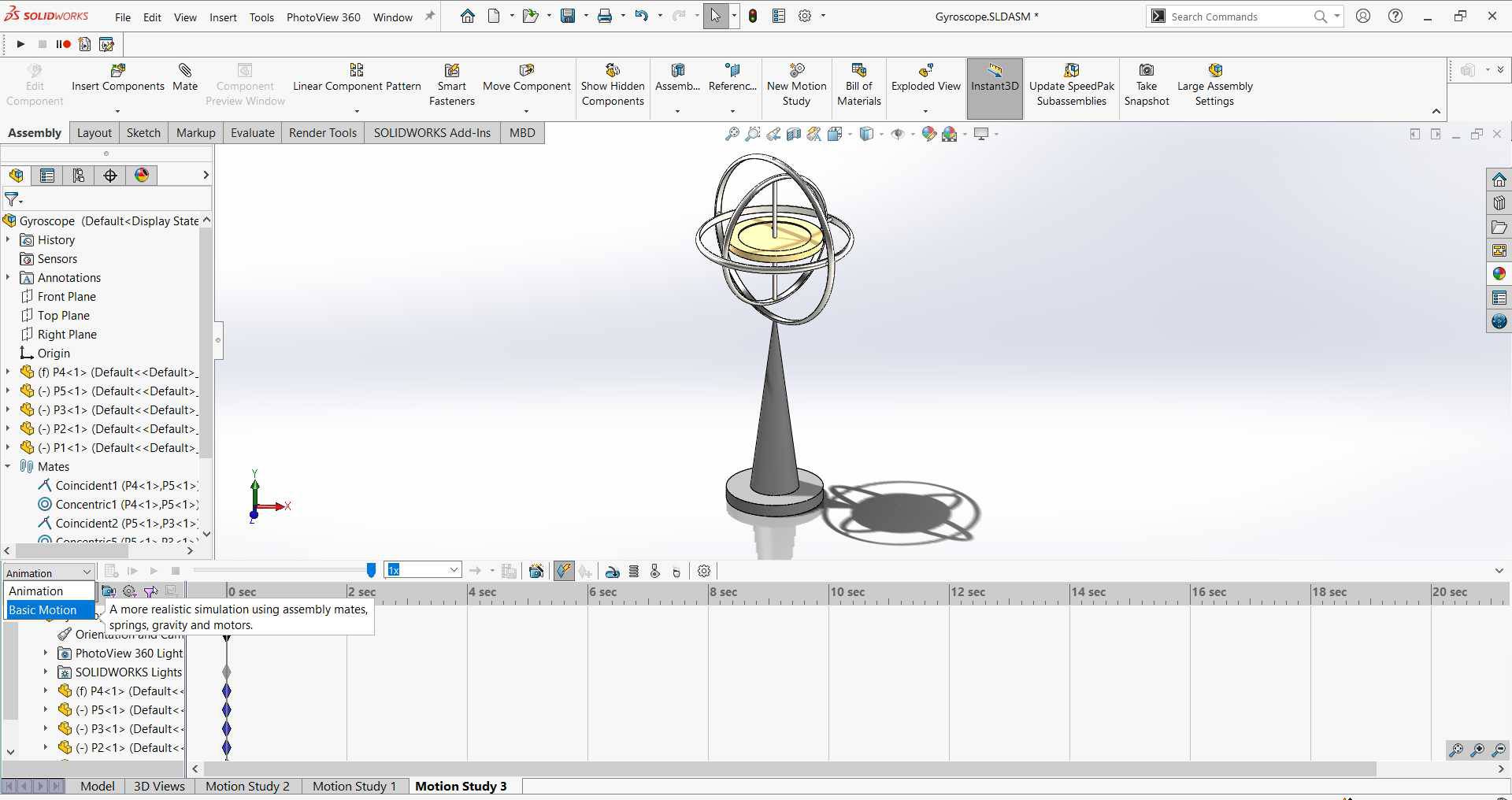
First when you want to start with motion, set the model to the view that you want to start the motion from, then from the bottom taps right click and select Create New Motion Study.
Then at the left top of motion study bar you will find Animation so change it to Basic Motion "I'm not professional yet but this is the option which worked well with me". -
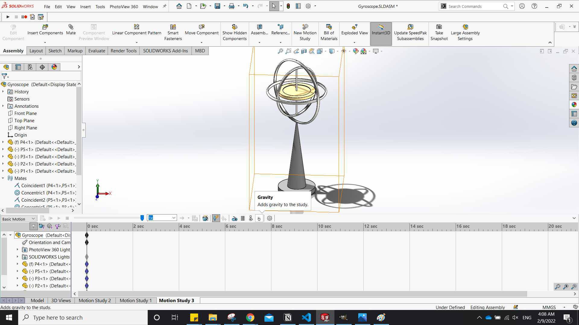
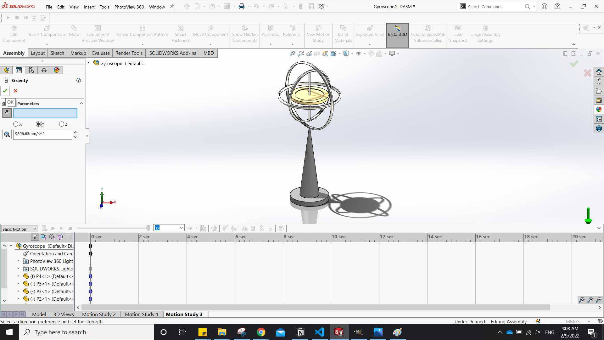
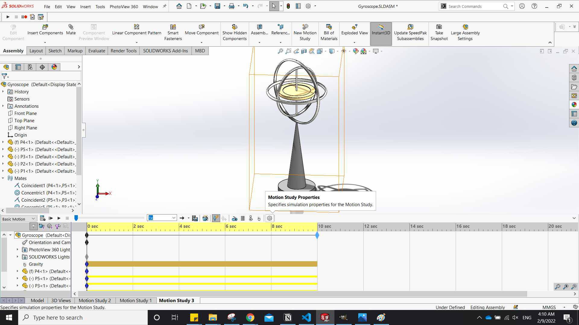
Now add gravity from the tools listed in the top bar of motion study panel, and selected the gravity to be in y axis.
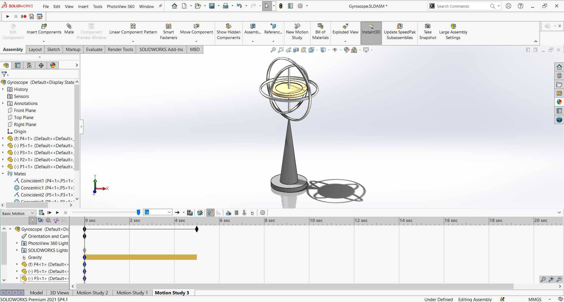
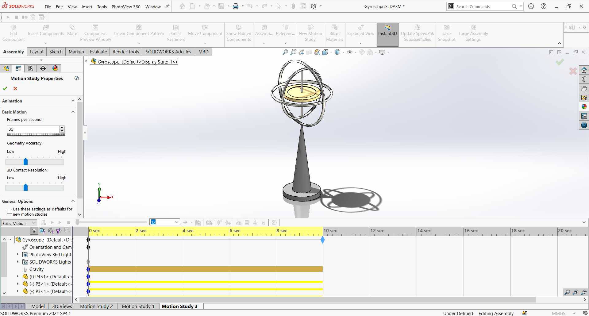
when clicked ok it gave me a time bar of 5 secs so I grabbed the black diamond at the top of the time section and dragged it to 10 sec. - From Motion Study Properties I edited the frames per seconed.
-
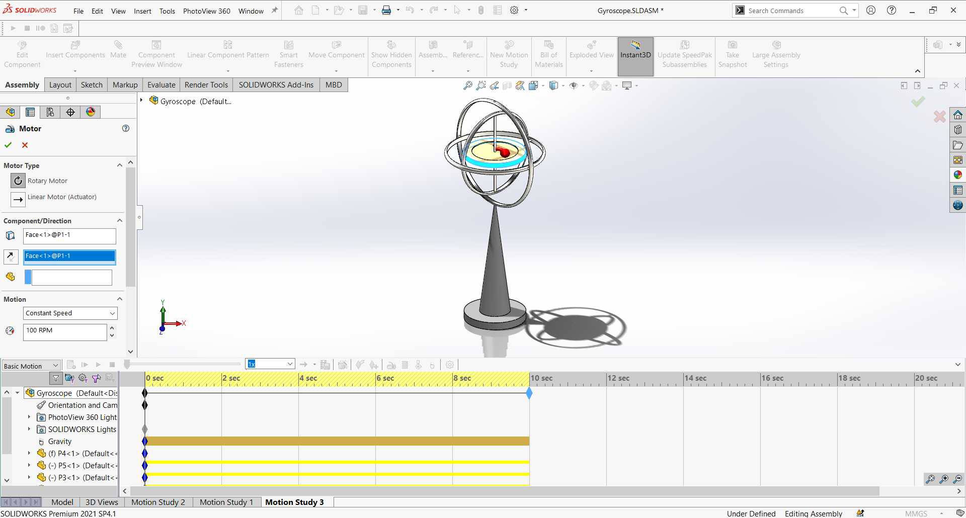
Next step is to add a motor to the inner desk so when it rotates it should maintain the balance of the gyroscope against gravity, When Turned off it slows down and gravity takes effect.
to do that I clicked on the motor button then selected the radial surface of the inner desk (it doesn't really matter what face you select) and set as constant speed.
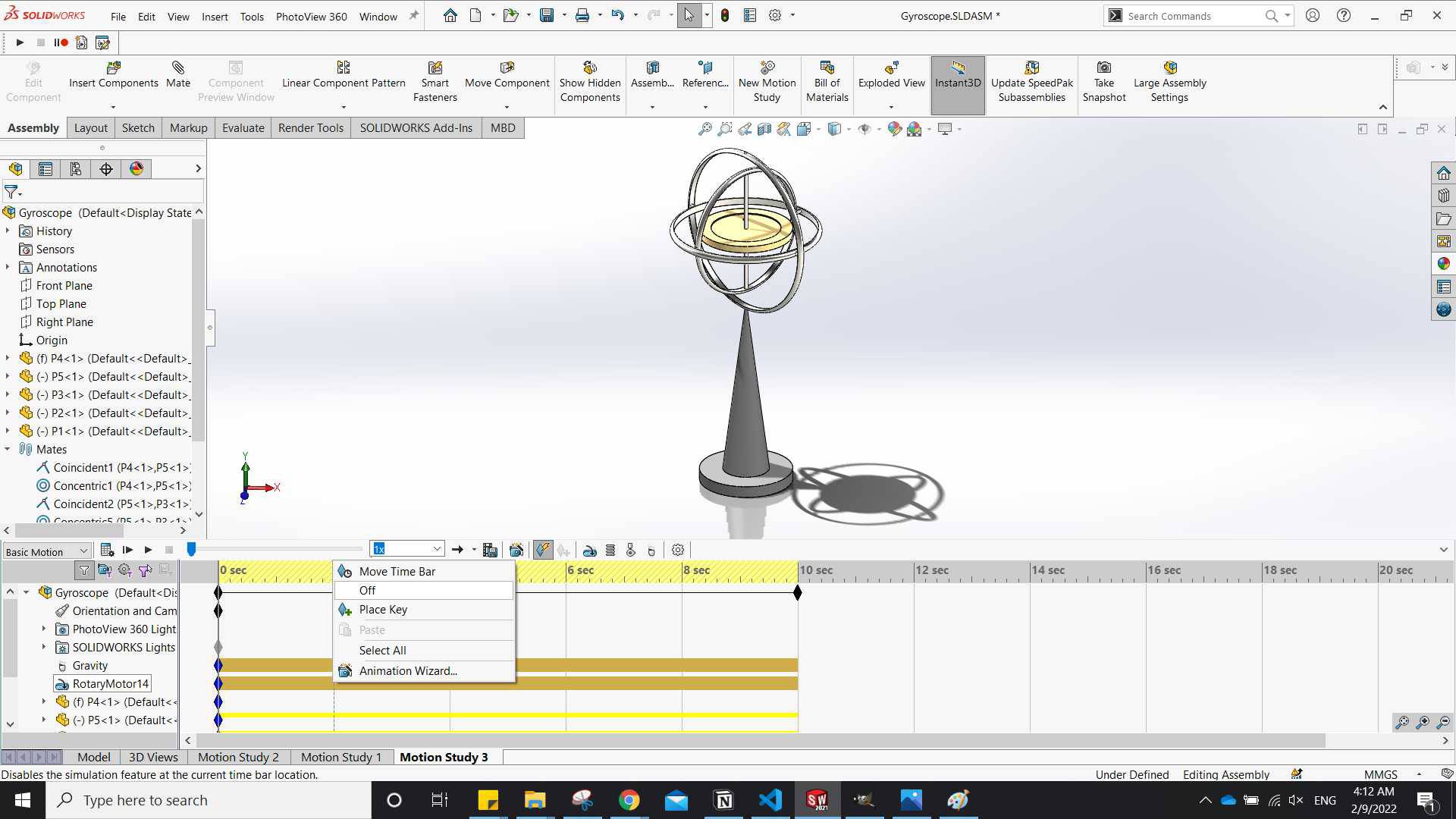
When I click ok the motor takes effect along the 10 seconeds so I right click on the motor bar in time section and placed an off key at 2 seconeds. -
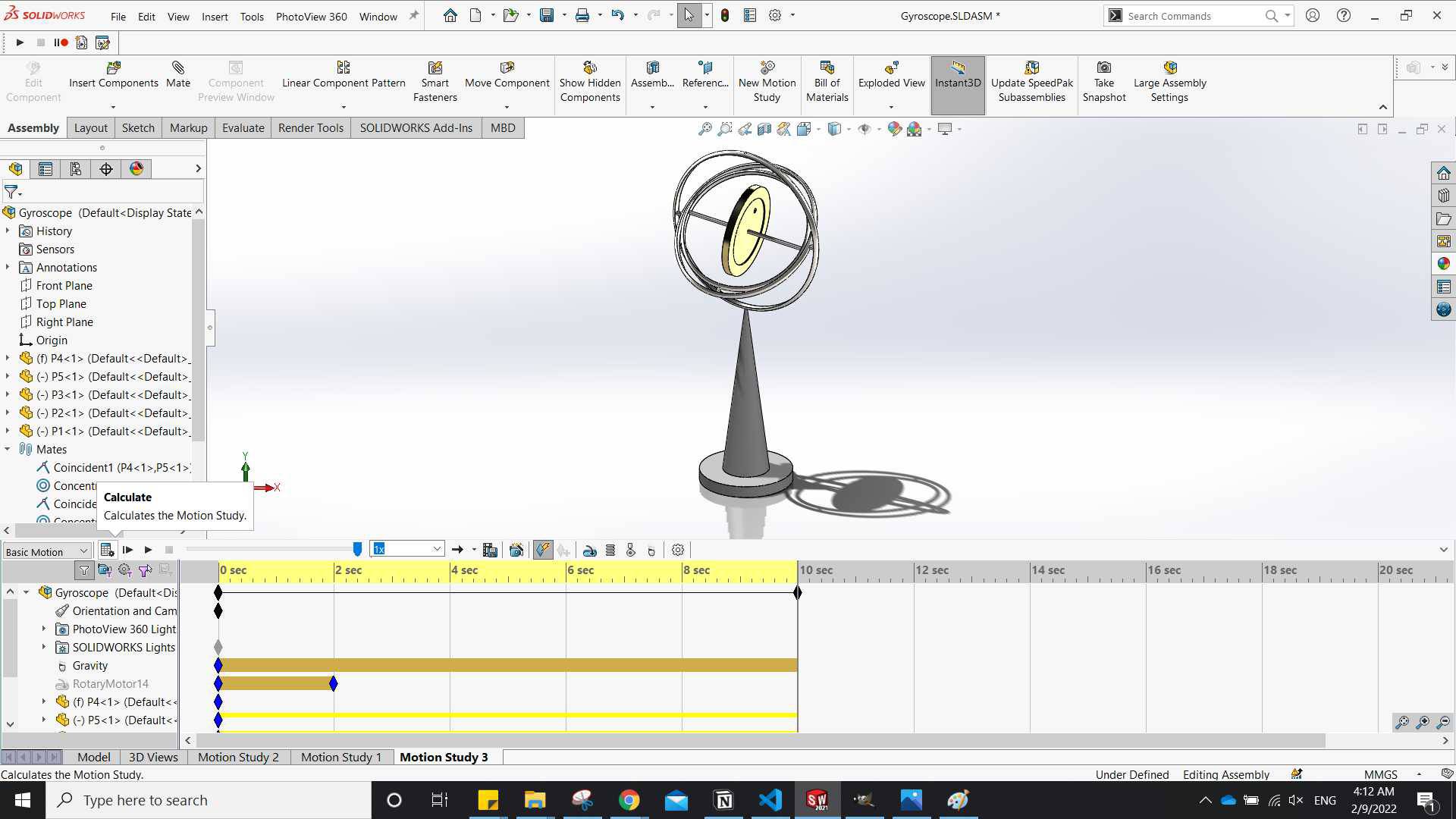
Now I clicked on the calculate button and the animation worked fine, "of course this was not my first try, it was like the 5th try or something"
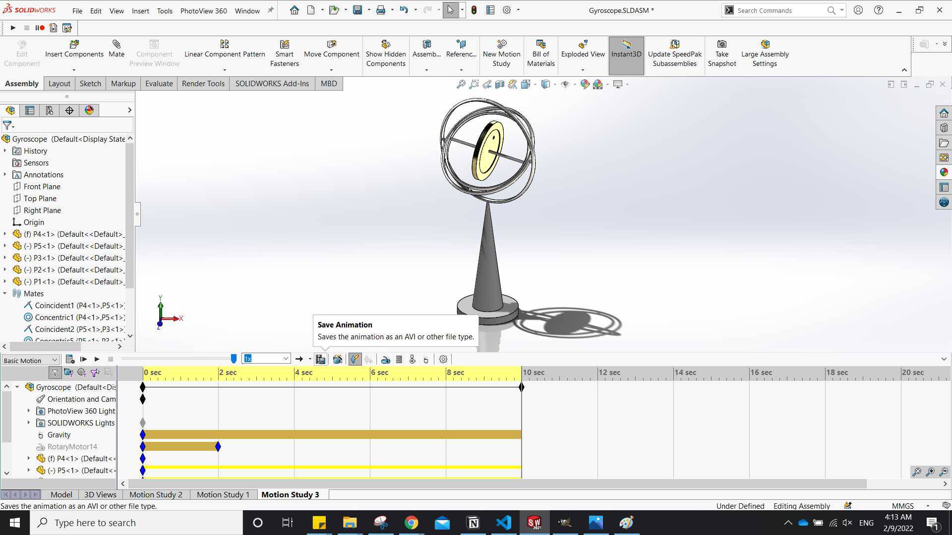
after playing the animation over and over because I liked it I went to Save it. -
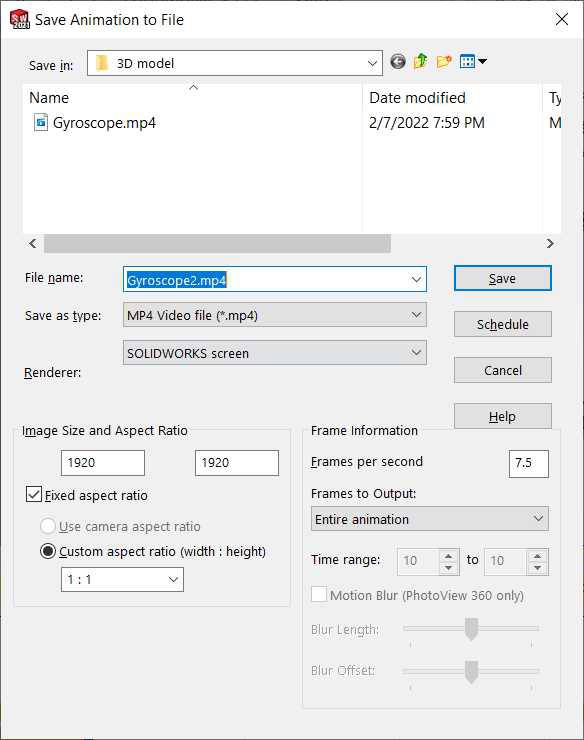
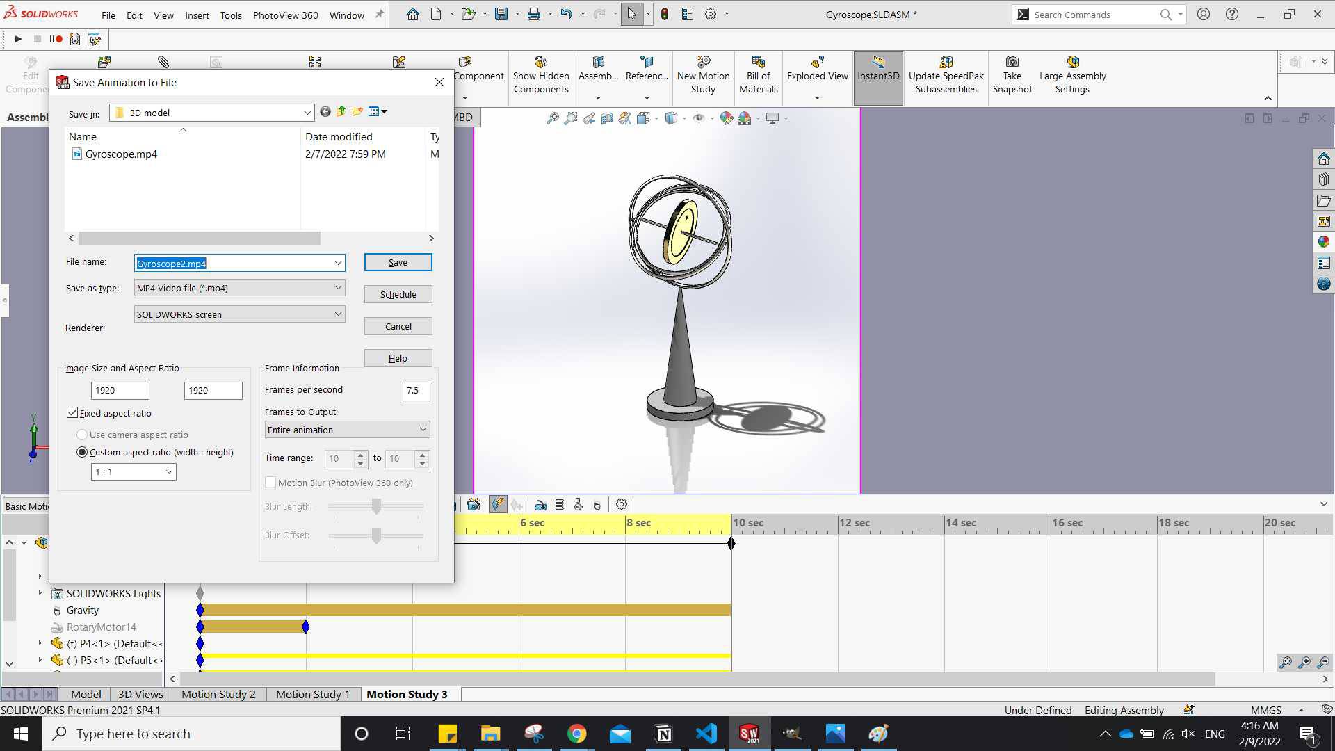
When I clicked Save Animation the default save format was Avi so I changed it to mp4.
also by changing the custom aspect ration at the bottom I selected how I want the screen to be. - Finally the Video.
Downloads:
Gyroscope Parts.rar Final Project raster Final Project VectorAknowledge:
- Thanks to Abo Elnaga and Saeed, I have learned alot from their websites.
- Thanks to students who's taking the fab academy with me for the continuos positve attitude and support.