Project Development
Learning outcomes:
- Implement project plan
- Apply time management techniques
- Summarise and communicate the essence of your project development
Assessment criteria
- what tasks have been completed, and what tasks remain?
- what has worked? what hasn't?
- what questions need to be resolved?
- what will happen when?
- what have you learned?
Project Initial idea
 I have spent much time thinking what should be my final project, that lead me to many questions like what do I like to do, what is my hoppy, what would I enjoy while doing.
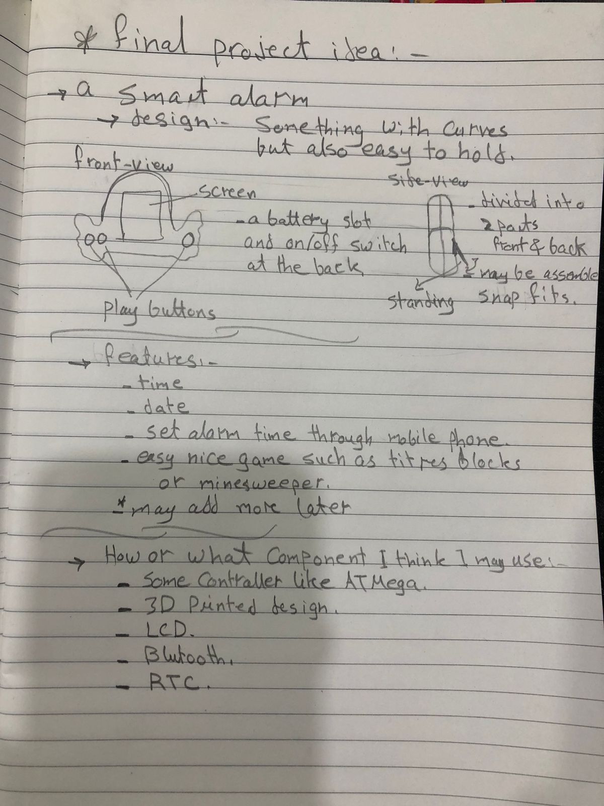
Then I came to the important question, what will satisfy the Academy requirements and also be usefull for me, and the first thought was a smart alarm.
What do I mean with smart alarm, with help from our local mentor I decieded that the alarm should have a kind of a game and you will have to pass a level at this game to shut off the alarm.
Why alarm?, I like the stand alone alarms not the mobile alarms and I wanted to implement a fun idea into it.
So lets call my prject
Smart Alarm
Features
- Shows time.
- Shows date.
- Set multiple alarms with your phone.
- Has a cool game, maybe titres or minesweeper.
Who will use it, I think everyone who likes cool stuff around and also doesn't like phone alarms.
How will I make it or what components may I use
- LCD.
- Push buttons.
- Microcontroller like ATMega.
- Blutooth.
- RTC.
- Blutooth.
With the help of my instructors We created a project tracking sheet where I listed down all tasks I imagine I need to make during my final project and distributed them on days to have a display of what I have done, what's left to finish which helped alot in time management.
Project Proposal
Idea
Smart Alarm is a simple alarm which displays current time and data, and you can set your alarms, and there will be a game that you have to win to stop the alarm.
General Specification of the alarm
Modules breakdown
- CAD + Manufacturing
- - Enclosure
- - Buttons
- Output/Input devices
- - 7-segments displays
- - Push buttons
- - On/off Switch
- - RTC module
- - Buzzer/speaker
- Programming
- - Code
Alarm features
- Minimum
- - Display date & time
- - Alarm working
- - Game working
- Complete
- - Setting multiple alarms
- - Stopping alarm depends on winning a game
Project time line
- Display & RTC
- - Operate 7-segments on ATtiny1614
- - Integrate RTC with 7-segments to display time
- Alarm
- - Set Alarm and operate speaker
- - Set multiple alarms
- Game
- - Add a game to the code and test it
- - Integrate the game with alarm
- - Add buttons for navigation and game play
- Enclosure
- - Design & Manufacturing
- - PCB Design
- - Assembly and testing
- Testing
- - Testing for a long time
- - Design and Manufacturing any updates/edits
- - Video showing off
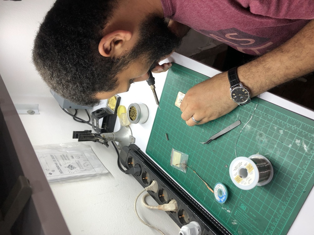
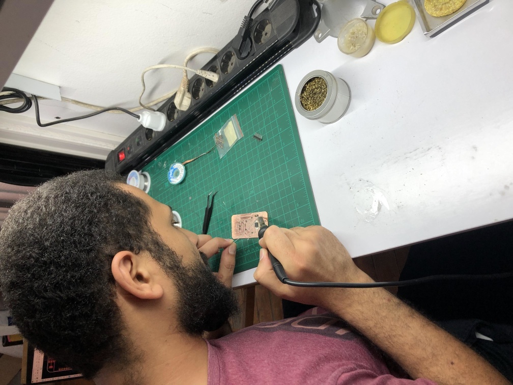
Project Progress
For a brief and direct steps of the final project you can go to my Final project page, here I will be writing down in details what I have been through and failed or abandoned trials.
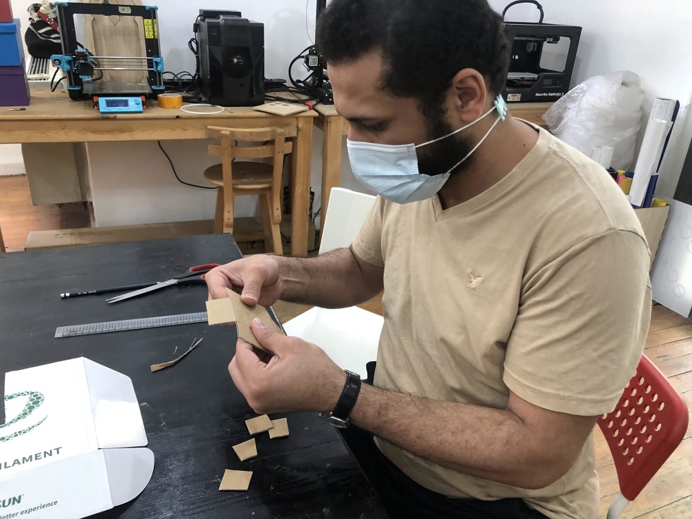
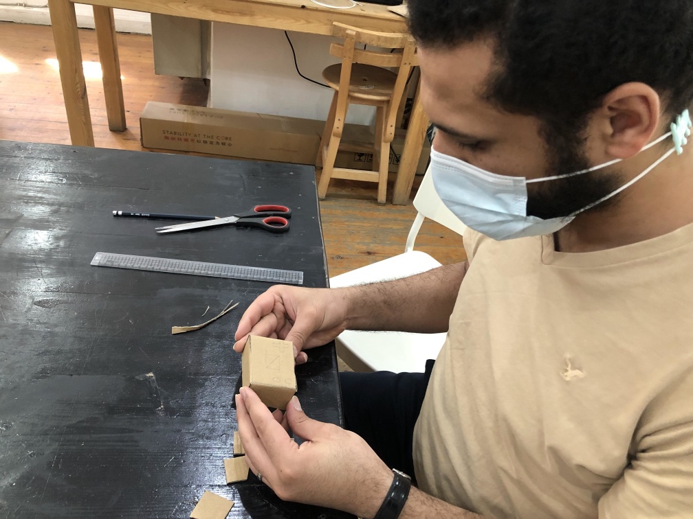
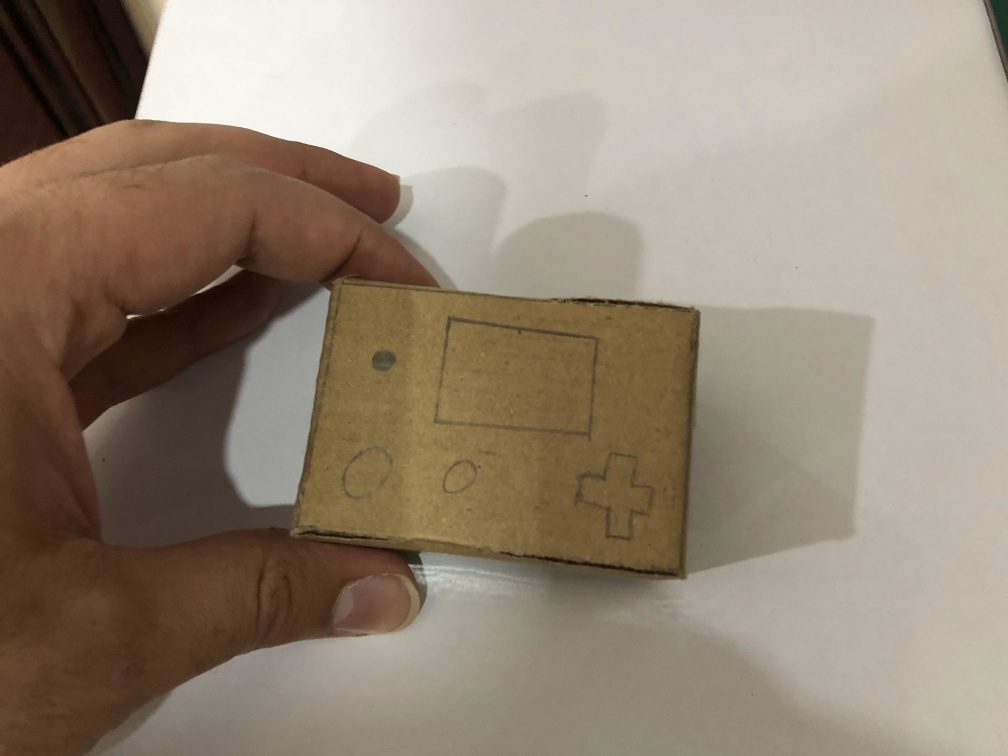
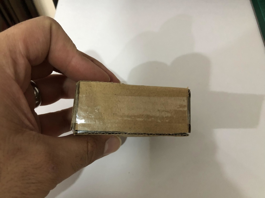
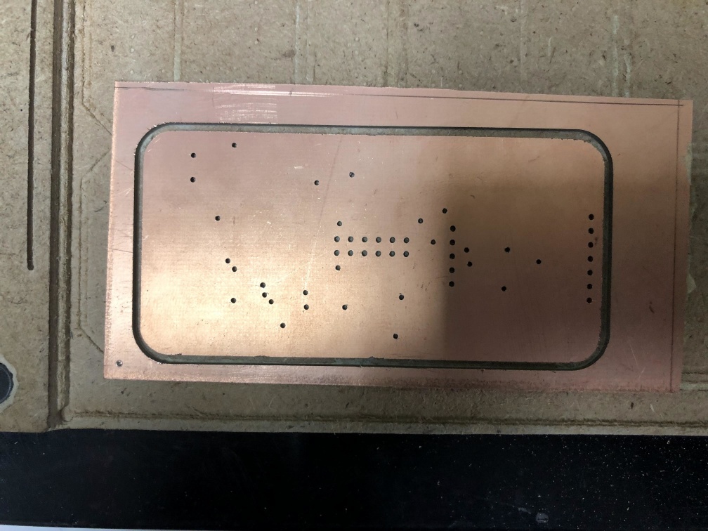
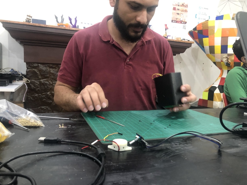
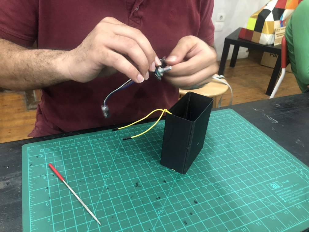
Cardboard prototype
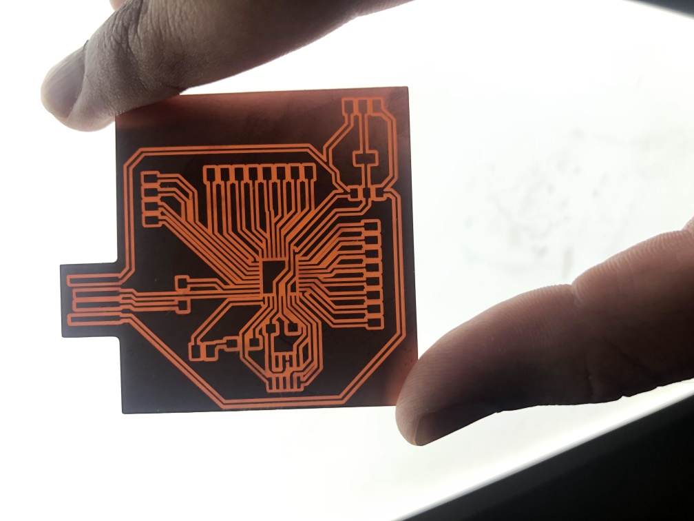
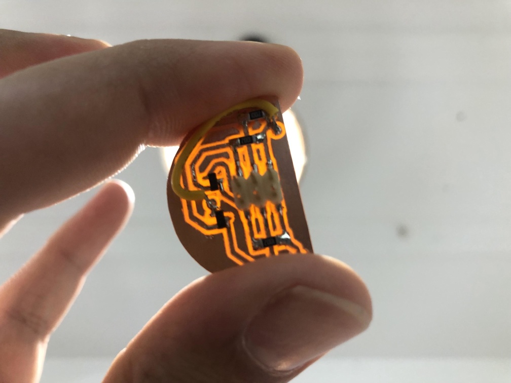
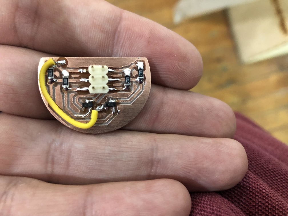
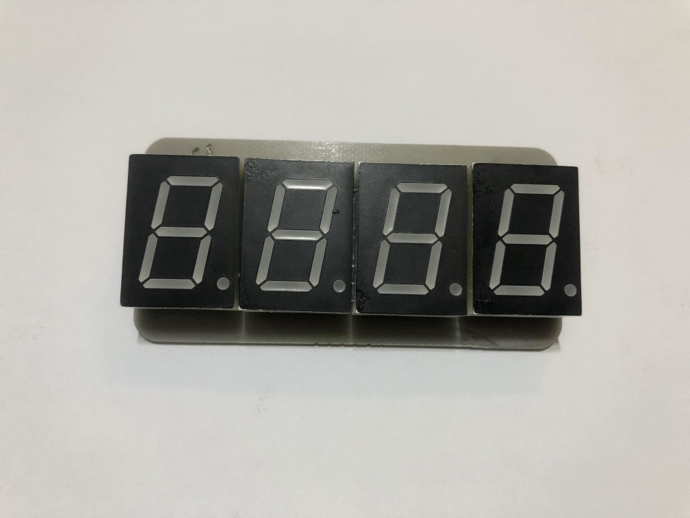
7 Segment PCB
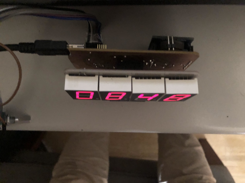
I have changed the Display to 7 Segment as I wanted the clock to have a full screen display of the numbers also, I wanted to have a bigger display of the numbers.
- I used 0.8 inch common anode 7 segment display, 4 of them and made a PCB to have a 4 digit of it.
- The main function of this board is to all segments of the same address (all a together and all b, .... etc), so that we can control the 4 digit with only 11 pins, 7 pins for leds and 4 to control which one will light up.
- later I removed the bottom part, I wanted to display date on it but I didn't have enough pins to control it so I removed it for now.
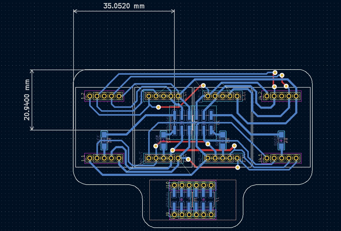
- After testing that, there's a better way to do this PCB to put a resistor on each led pin instead of the control pin because that makes the digits varry in brightness depening on how many leds are on to display the number on it.
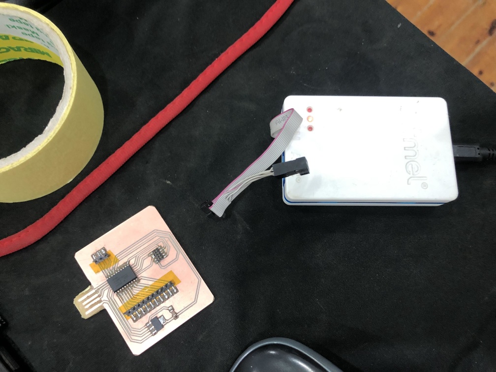
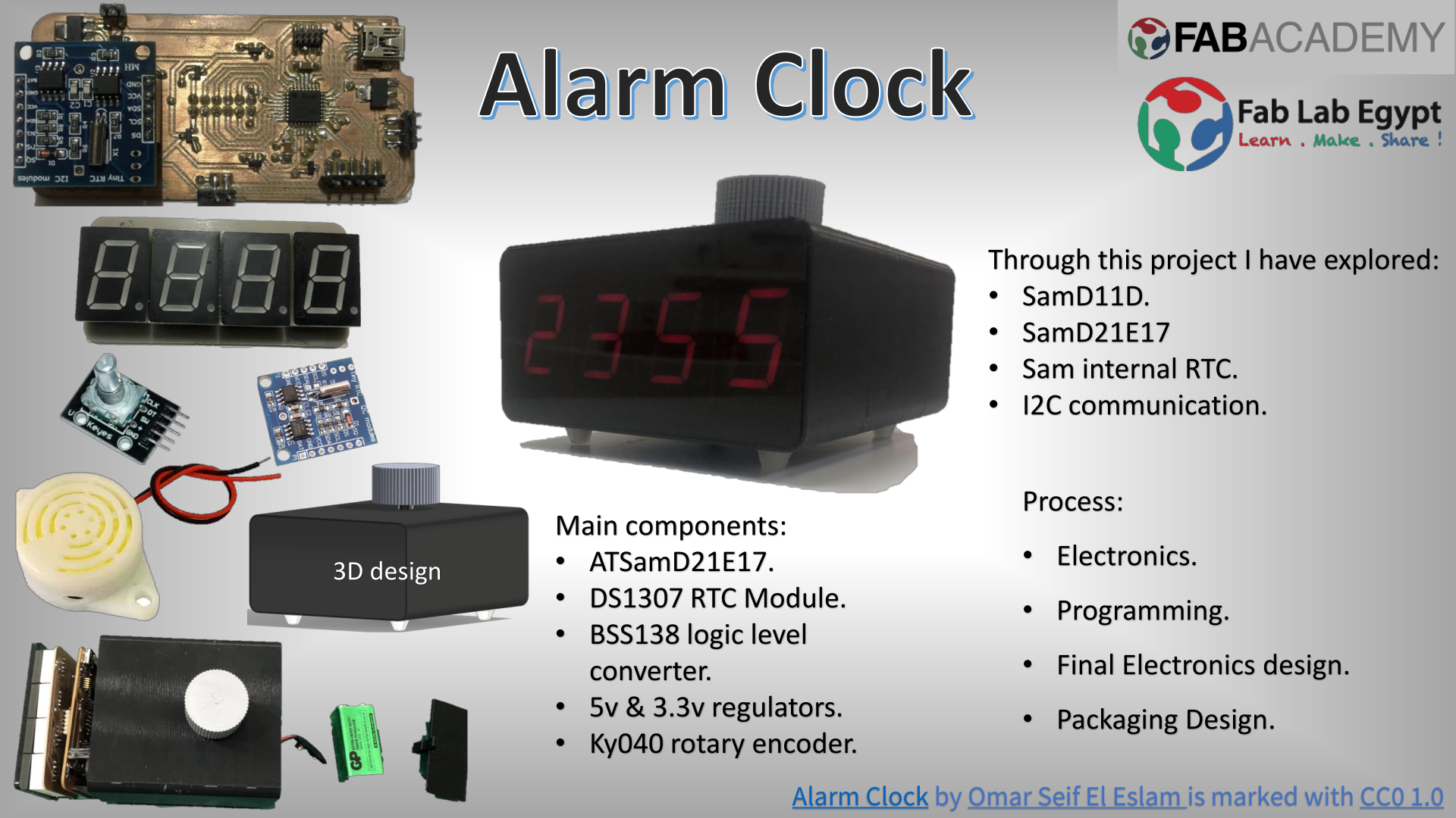
ِATSamD11D
I started with the SamD11D MCU, the idea were to use 2 of it one for display and one for the other components and communicate them with I2C.
- I have operated the clock with 2 SamD11D communicating through I2C.
- One were just displaying a number on the 7 segment and the other used internal RTC using RTCzero library.
- I had a problem that the test code already took 95% of the flash memory size of it.
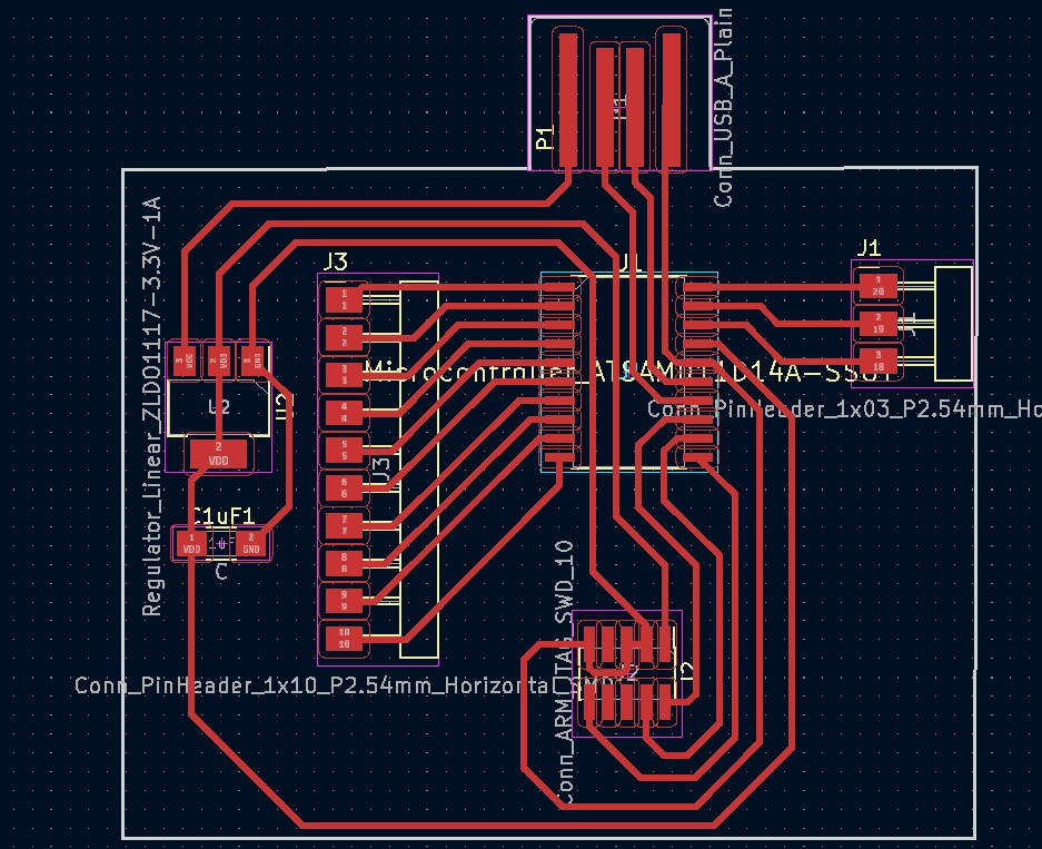
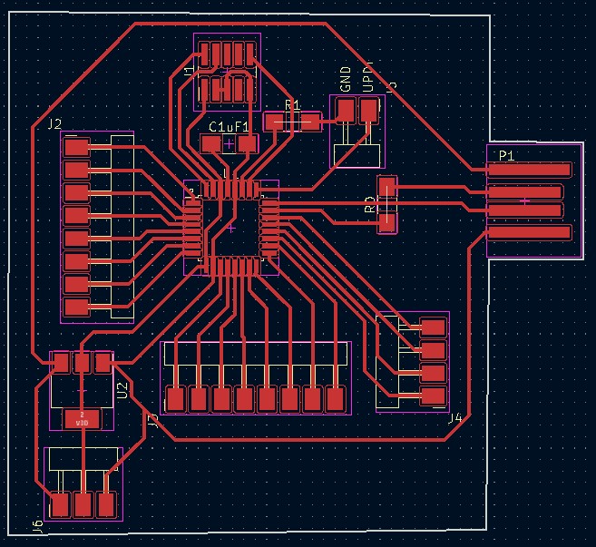
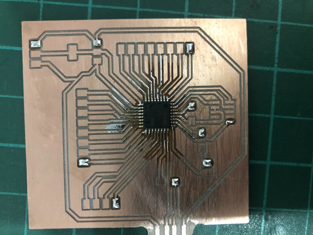
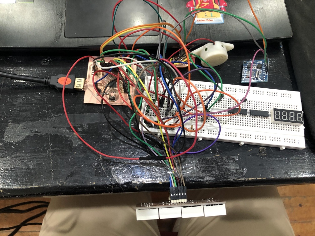
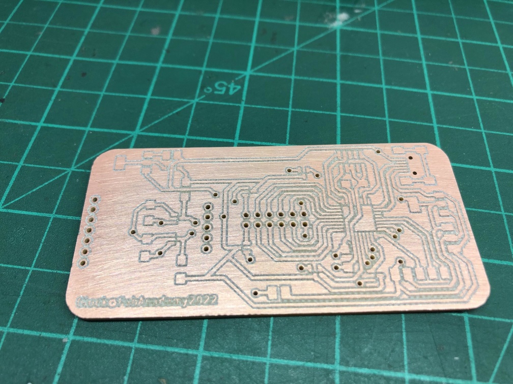
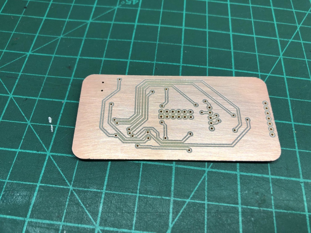
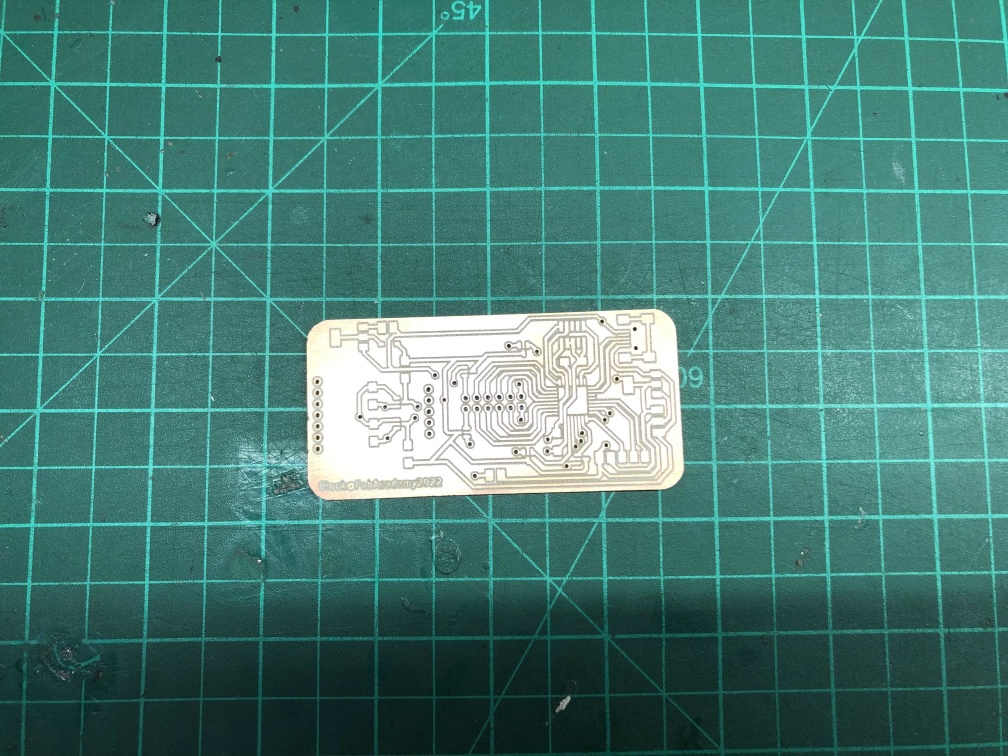
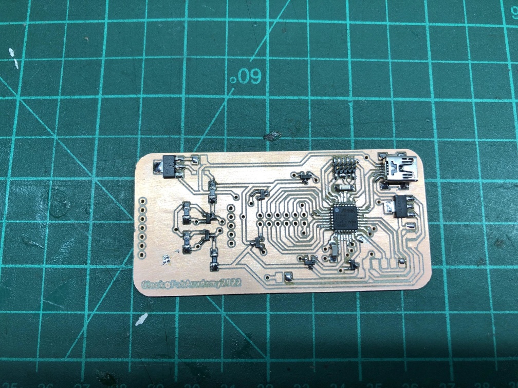
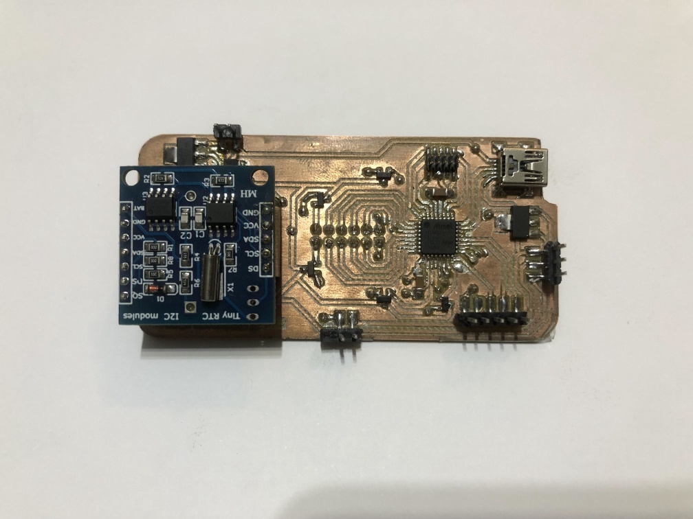
ATSamD21E17
After facing the memory size problem I decided to use the SamD21E.
- I tried the same code with internal RTC but it didn't work properly, I'm sure there's a way to make it work but I can't do it in my current level.
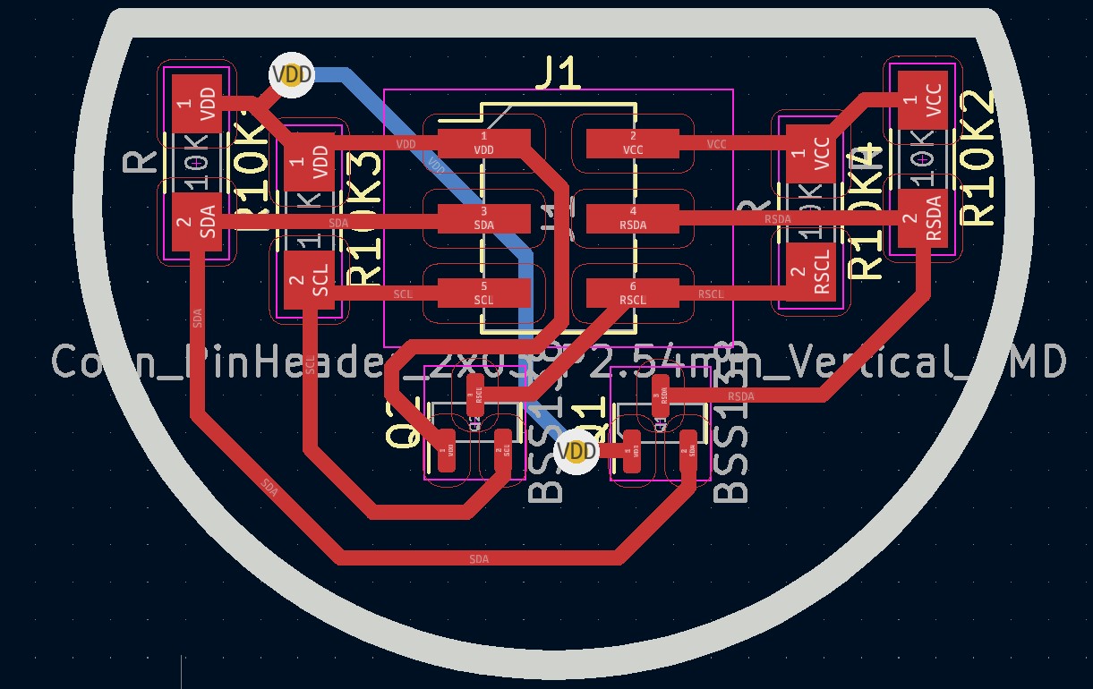
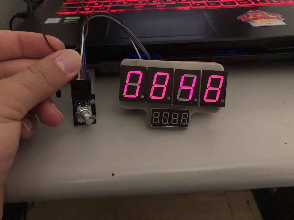
- After a few trials I had an RTC module DS1307 so I used it with logic level converter.
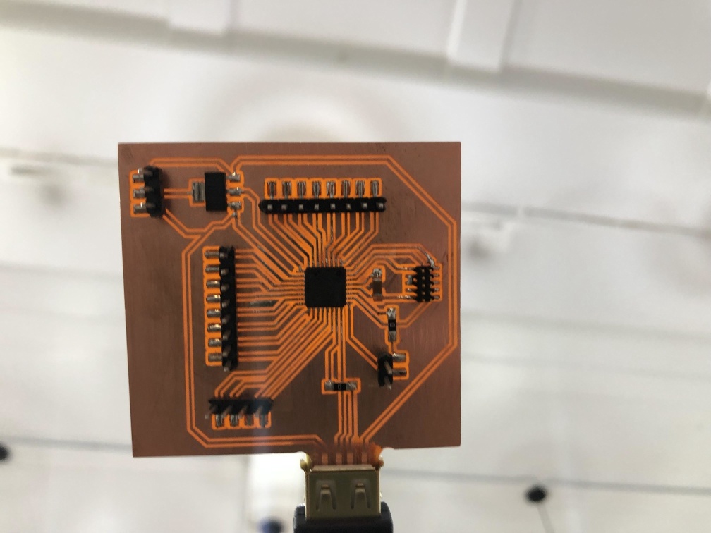
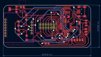
- It worked fine so I went to the PCB design for a full board that has the same outline as the 7 segment PCB to get the minimum size for the clock.
Programming
- For programming I had 4 main parts, 1st part is the part that controls the display, 2nd part is the part that reads and updates that time from the RTC, 3rd part is the alarm and the last part is the rotart encoder intrupt.
- For 7 Segments display I used "SevSeg.h" liberary it's a good liberary to control a 4 digit seven segment you need to enter the pins you have the 7 segments on and the 4 digit number you want to display.
- The liberary mainly refreshing the display at a high frequency to be able to display the number on the 4 digits at the same time.
- I used "RTClib.h" to set the time of the clock and get the updated time to display.
- I used Interupt to use the rotary encoder to control the display.
- To set the Alarm I used some if and while functions and I'm sure it can be done in a better way but I'm not a good programmer yet.
  // Date and time functions using a DS1307 RTC connected via I2C and Wire lib
  #include "RTClib.h"

  RTC_DS1307 rtc;

  char daysOfTheWeek[7][12] = {"Sunday", "Monday", "Tuesday", "Wednesday", "Thursday", "Friday", "Saturday"};

  //------Electronics-project-hub.com-----//
  #include "SevSeg.h"
  SevSeg Display;
  //const int hrs_btn = 31;
  //const int min_btn = 30;
  //const int ledPin = 2;
  //int Hrs = 12;
  //int Min = 0;
  //int Sec = 0;
  int Time;
  int ledState = LOW;

  // Rotary Encoder Inputs
  #define CLK 19
  #define DT 18
  #define SW 15

  int counter = 0;
  int currentStateCLK;
  int lastStateCLK;
  String currentDir = "";
  int pinState = HIGH;
  int AH1 = 17;
  int AM1 = 23;
  int AH2 = 13;
  int AM2 = 37;
  int alarm1time;
  int alarm2time;
  char sitAlarm[][5] = {"a1--", "a2--"};

  //speaker pin
  #define SPKR 14


  void setup () {
    Serial.begin(9600);
    // Set encoder pins as inputs
    pinMode(CLK, INPUT);
    pinMode(DT, INPUT);
    pinMode(SW, INPUT_PULLUP);
    pinMode(SPKR, OUTPUT);


    if (! rtc.begin()) {
      //Serial.println("Couldn't find RTC");
      //Serial.flush();
      while (1) delay(10);
    }

    if (! rtc.isrunning()) {
      //Serial.println("RTC is NOT running, let's set the time!");
      // When time needs to be set on a new device, or after a power loss, the
      // following line sets the RTC to the date & time this sketch was compiled
      rtc.adjust(DateTime(F(__DATE__), F(__TIME__)));
      // This line sets the RTC with an explicit date & time, for example to set
      // January 21, 2014 at 3am you would call:
      // rtc.adjust(DateTime(2014, 1, 21, 3, 0, 0));
    }

    // When time needs to be re-set on a previously configured device, the
    // following line sets the RTC to the date & time this sketch was compiled
    //rtc.adjust(DateTime(F(__DATE__), F(__TIME__)));
    // This line sets the RTC with an explicit date & time, for example to set
    // January 21, 2014 at 3am you would call:
    // rtc.adjust(DateTime(2014, 1, 21, 3, 0, 0));


    byte numDigits = 4;
    byte digitPins[] = {10, 8, 9, 11};
    byte segmentPins[] = {3, 2, 4, 7, 6, 0, 1, 5};
    bool resistorsOnSegments = true;
    bool updateWithDelays = false;
    byte hardwareConfig = COMMON_ANODE;
    bool leadingZeros = true;
    bool disableDecPoint = true;
    Display.begin(hardwareConfig, numDigits, digitPins, segmentPins, resistorsOnSegments, updateWithDelays, leadingZeros, disableDecPoint);
    Display.setBrightness(100);


    // Read the initial state of CLK
    lastStateCLK = digitalRead(CLK);


    // Call updateEncoder() when any high/low changed seen
    // on interrupt 0 (pin 2), or interrupt 1 (pin 3)
    attachInterrupt(CLK, updateEncoder, CHANGE);
    attachInterrupt(DT, updateEncoder, CHANGE);
    //attachInterrupt(SW, updateEncoder, CHANGE);


  }

  void loop () {

    if (digitalRead(SW) == 0)
    {

      while (digitalRead(SW) == 0)
        Display.blank();

      Serial.println("SW");

      alarmx();

    }

    //out:

    DateTime now = rtc.now();

    int hh = now.hour();
    int mm = now.minute();

    Time = hh * 100 + mm;
    //Serial.println(now.second());
    Display.setNumber(Time);
    Display.refreshDisplay();

    alarm1time = AH1 * 100 + AM1;
    Serial.println(alarm1time);

    alarm2time = AH2 * 100 + AM2;

    if (alarm1time == Time || alarm2time == Time)
      speaker();

    else
      digitalWrite(SPKR, 0);

  }

  void updateEncoder() {
    // Read the current state of CLK
    currentStateCLK = digitalRead(CLK);

    // If last and current state of CLK are different, then pulse occurred
    // React to only 1 state change to avoid double count
    if (currentStateCLK != lastStateCLK  && currentStateCLK == 1) {

      // If the DT state is different than the CLK state then
      // the encoder is rotating CCW so decrement
      if (digitalRead(DT) != currentStateCLK) {
        counter --;
        currentDir = "CCW";
      } else {
        // Encoder is rotating CW so increment
        counter ++;
        currentDir = "CW";
      }

      Serial.print("Direction: ");
      Serial.print(currentDir);
      Serial.print(" | Counter: ");
      Serial.println(counter);
    }

    // Remember last CLK state
    lastStateCLK = currentStateCLK;


  }


  void alarmx() {
    int i;
    counter = 0;
    while (1) {


      //Display.setChars("nn");
      //Display.setSegmentsDigit(2, Am10s);
      //Display.setSegmentsDigit(3, Am1s);
      Display.setChars(sitAlarm[i]);
      Display.refreshDisplay();
      Serial.println(sitAlarm[i]);


      i = counter ;

      if (digitalRead(SW) == 0) {

        while (digitalRead(SW) == 0)
          Display.blank();


        goto swtch;
      }

    }

  swtch:
    switch (i) {
      case 0:
        while (1) {

          Display.setChars("nn");
          Display.refreshDisplay();

          if (digitalRead(SW) == 0) {

            while (digitalRead(SW) == 0)
              Display.blank();

            while (1) {


              //Display.setChars("nn");
              //Display.setSegmentsDigit(2, Am10s);
              //Display.setSegmentsDigit(3, Am1s);
              Display.setNumber(AM1);
              Display.refreshDisplay();
              Serial.println(AM1);


              AM1 = counter ;

              if (digitalRead(SW) == 0) {

                while (digitalRead(SW) == 0)
                  Display.blank();


                while (1) {
                  Display.setChars("hh");
                  Display.refreshDisplay();

                  if (digitalRead(SW) == 0) {

                    while (digitalRead(SW) == 0)
                      Display.blank();

                    while (1) {


                      //Display.setChars("hh");
                      //Display.setSegmentsDigit(2, Am10s);
                      //Display.setSegmentsDigit(3, Am1s);
                      Display.setNumber(AH1);
                      Display.refreshDisplay();
                      Serial.println(AH1);


                      AH1 = counter ;

                      if (digitalRead(SW) == 0) {

                        while (digitalRead(SW) == 0)
                          Display.blank();


                        goto out;
                      }

                    }
                  }

                }
              }

            }
          }
        }
        break;

      case 1:

        while (1) {

          Display.setChars("nn");
          Display.refreshDisplay();

          if (digitalRead(SW) == 0) {

            while (digitalRead(SW) == 0)
              Display.blank();

            while (1) {


              //Display.setChars("nn");
              //Display.setSegmentsDigit(2, Am10s);
              //Display.setSegmentsDigit(3, Am1s);
              Display.setNumber(AM2);
              Display.refreshDisplay();
              Serial.println(AM2);


              AM2 = counter ;

              if (digitalRead(SW) == 0) {

                while (digitalRead(SW) == 0)
                  Display.blank();


                while (1) {
                  Display.setChars("hh");
                  Display.refreshDisplay();

                  if (digitalRead(SW) == 0) {

                    while (digitalRead(SW) == 0)
                      Display.blank();

                    while (1) {


                      //Display.setChars("hh");
                      //Display.setSegmentsDigit(2, Am10s);
                      //Display.setSegmentsDigit(3, Am1s);
                      Display.setNumber(AH2);
                      Display.refreshDisplay();
                      Serial.println(AH2);


                      AH2 = counter ;

                      if (digitalRead(SW) == 0) {

                        while (digitalRead(SW) == 0)
                          Display.blank();


                        goto out;
                      }

                    }
                  }

                }
              }

            }
          }
        }
      default:
        break;
    }

  out:
    delay(1);
  }


  void speaker() {

    digitalWrite(SPKR, 1);
  }
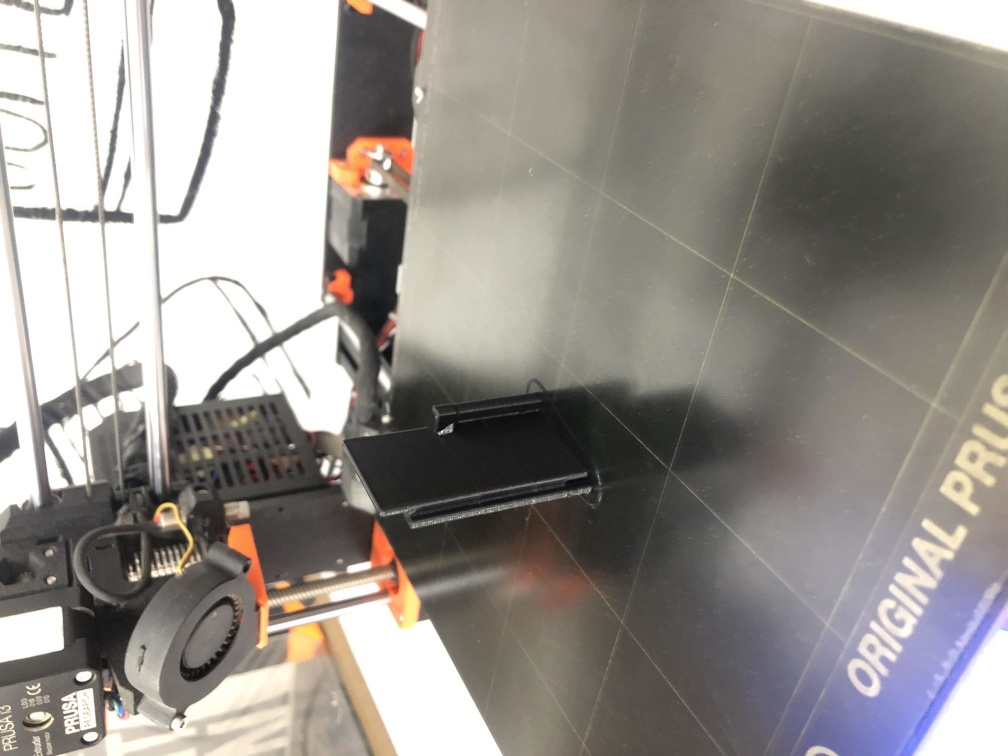
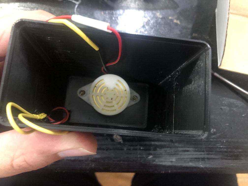
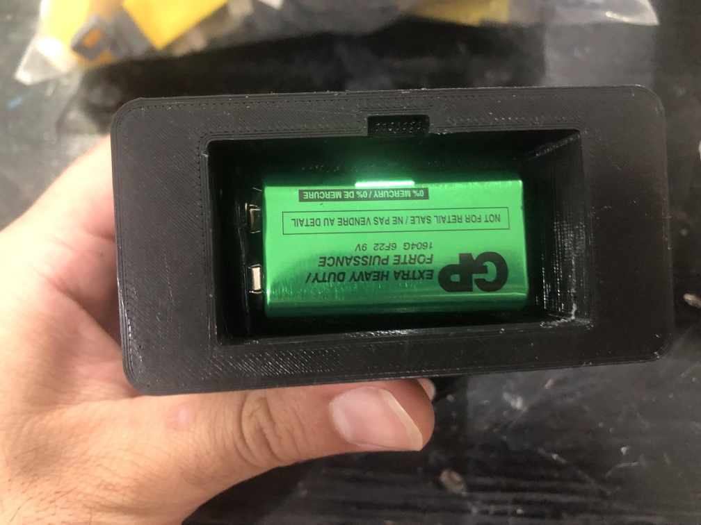
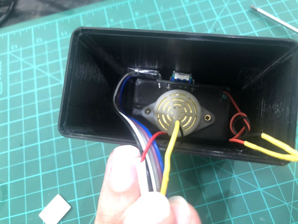
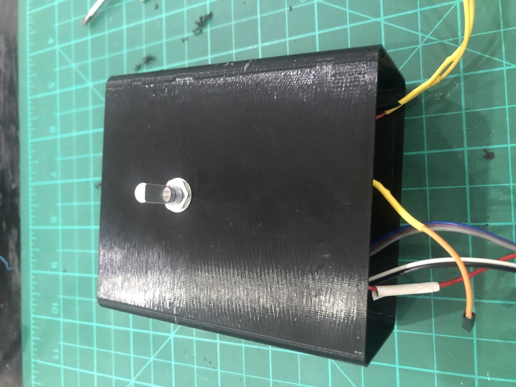
3D design
- for 3D desing I use Solidworks.
- Desing consists of 2D acrylic piece that is in the front and I used a laser cutting machine to make it.
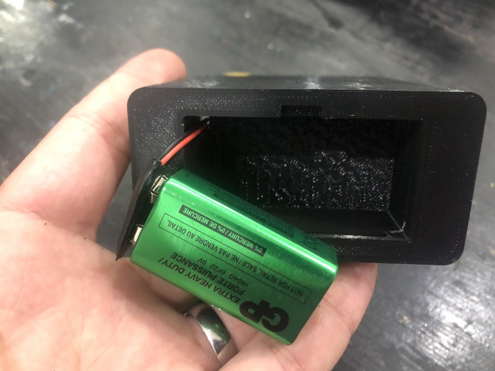
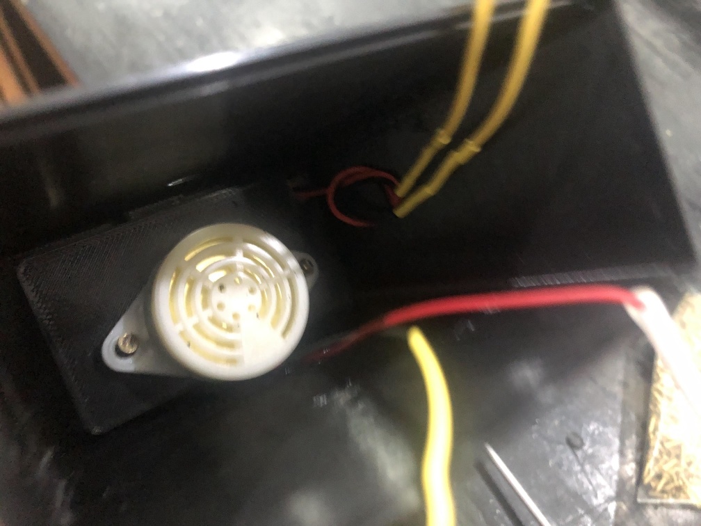
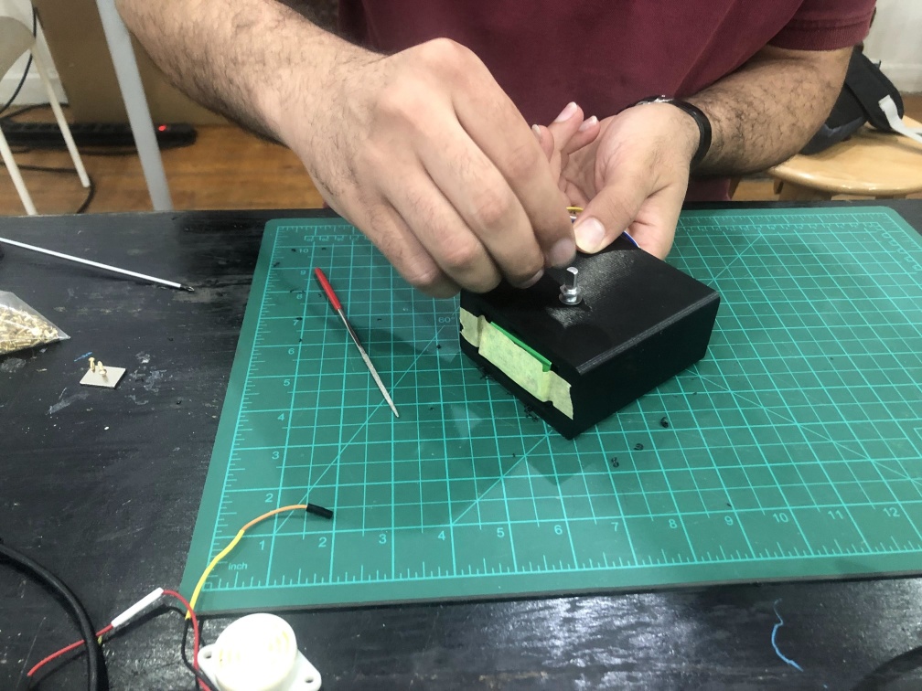
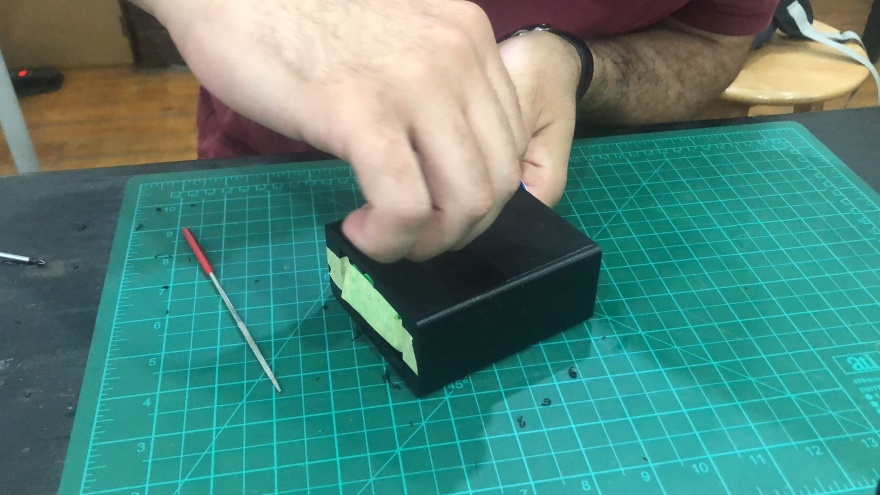
- The enclosure is 3D printed and it cosists of battery housing, speaker fixtures, encoder fixture and encoder knop.
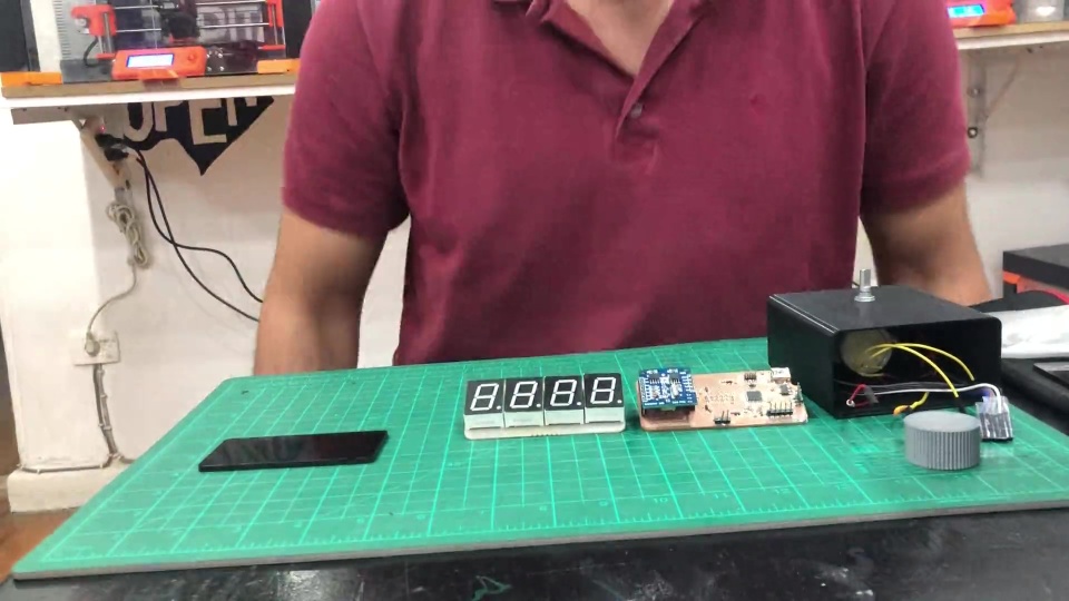
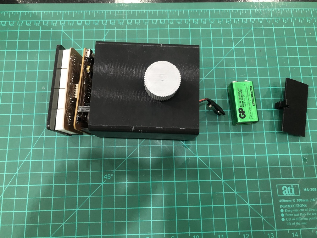
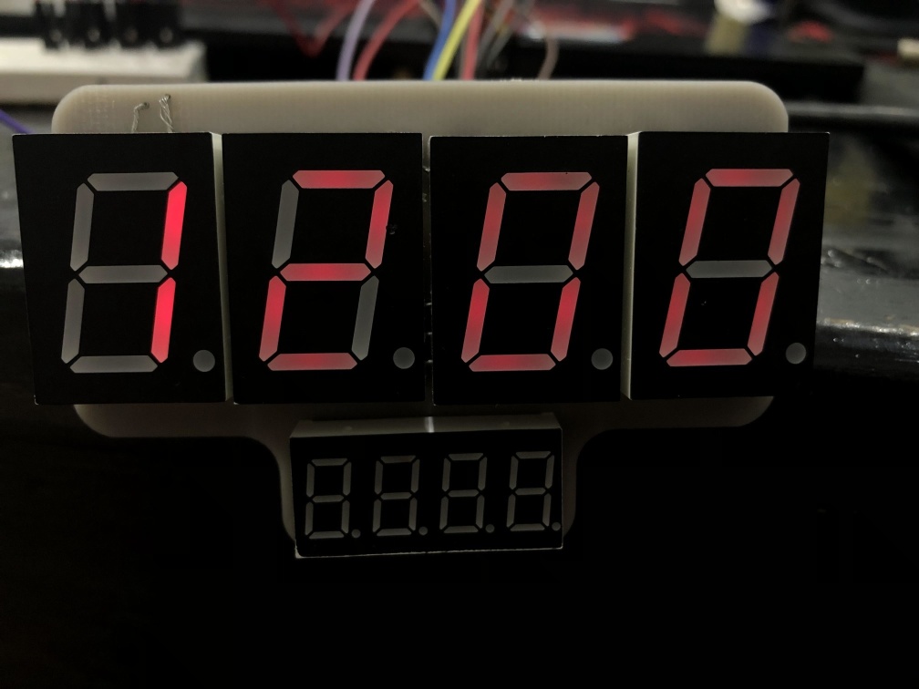
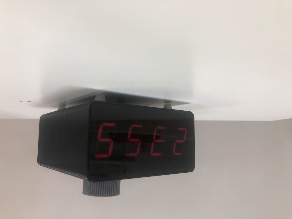
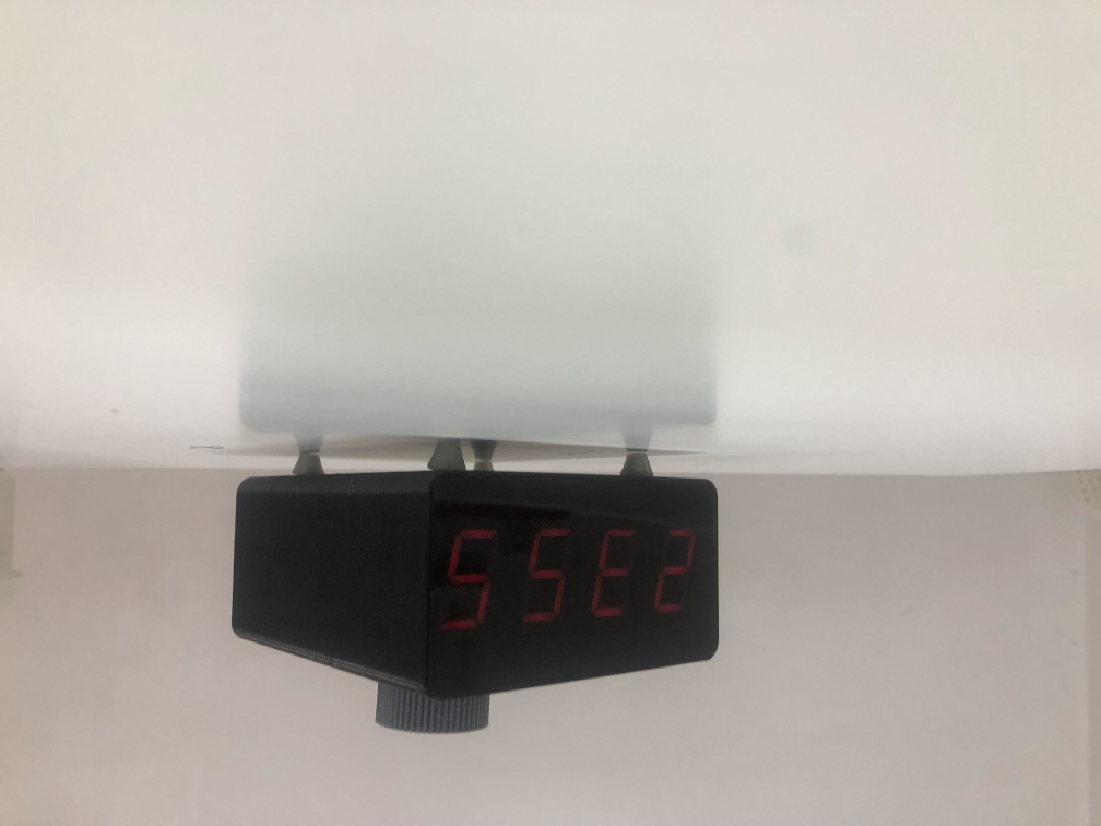
Output
Upgrades
- I couldn't finish the game code in time but I thought of a game that can be added when the alarm rings, to display a 3 digit binary number and by the rotary encoder in the 4th digit write the decimal number for it, if you wrote it right then the alarm stops.
- Also I would really think of another display because after testing the Alarm for few days it consumes alot of power, so I think 7 Segment if a power consuming component for an Alarm clock.
- Date could be easily added.