
Week 6
Electronics Design
This week we are designing, fabricating and programming some electronics.
- Group Assignment.
- Use the test equipment in your lab to observe the operation of a microcontroller circuit board
- Individual Assignment
- Redraw an echo hello-world board
- Add (at least) a button and LED (with current-limiting resistor)
- Check the design rules, make it, and test that it can communicate
Intro
First we will be talking about some basic electronic components that we will be using in order to understand the way they operate.
Resistor
Simply, a resistor is an electrical component that creates a resistance in the way of the current flow. It's measured in Ohms(Ω), and 1Ω resistor is able to resist a 1 Ampere(A) current that passes through a 1 Volt(V) voltage drop across its terminals.


IEC fixed resistor symbol ANSI fixed resistor symbol
And for actual components there are many different types and values of resistors. Some of them are variable resistors as Potentiometers, there are also Thermistors, LDRs and much more.
Here we can see the most common types of resistors.

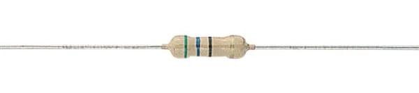
SMD Resistor Through-hole Resistor
Resonator
A resonator is a device or system that exhibits resonance or resonant behavior. That is, it naturally oscillates with greater amplitude at some frequencies, called resonant frequencies, than at other frequencies. The oscillations in a resonator can be either electromagnetic or mechanical (including acoustic). Resonators are used to either generate waves of specific frequencies or to select specific frequencies from a signal. It's measured in Hertz(Hz).
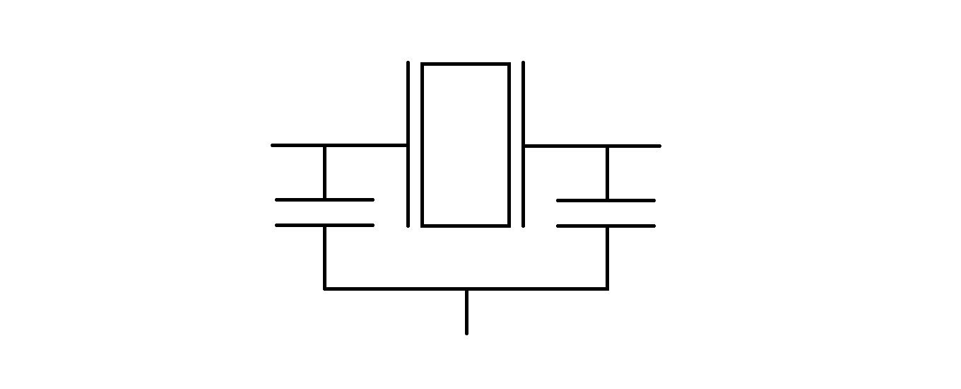

Resonator symbol Crystal symbol
Here we can see the most common types of resistors.
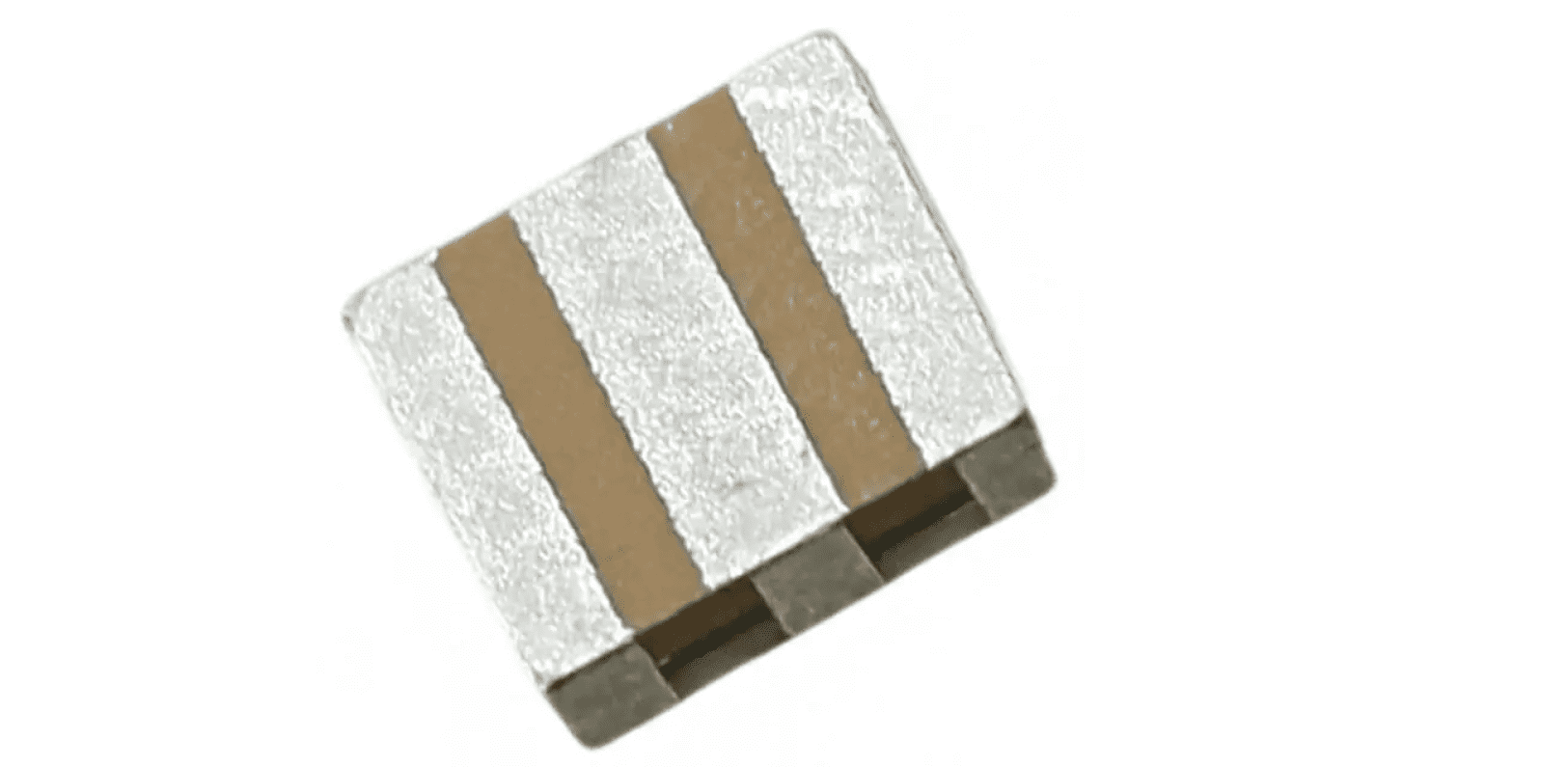
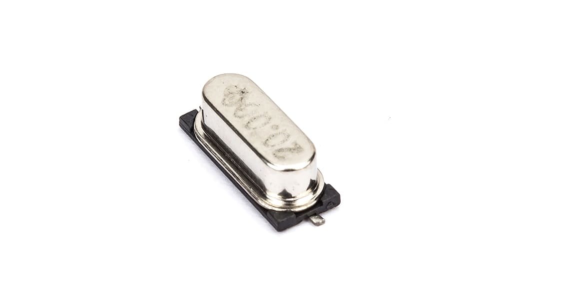
Different types of resonators
LED
A light-emitting diode (LED) is a semiconductor light source that emits light when current flows through it. Electrons in the semiconductor recombine with electron holes, releasing energy in the form of photons.
LEDs can now be used for a number of lighting applications and are available across the spectrum of visible, infrared, and ultraviolet light. Affordable 12V LED lights, for example, are often used as a conventional lighting source in homes, offices, and places of business because they are more energy-efficient, last longer, are more physically durable, and are safer than incandescent lighting sources.

LED symbol
Here we can see the most common types of resistors.
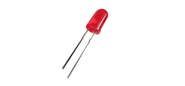
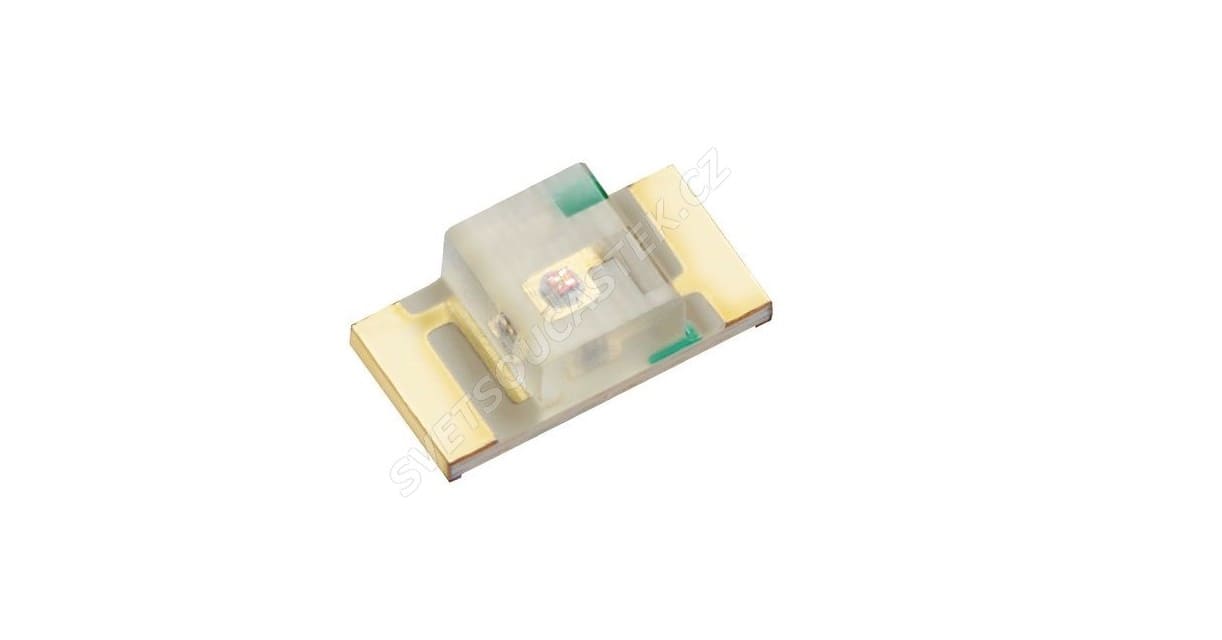
Through-hole LED SMD LED
Resources: EE Power, Wikipedia
Group Assignment
In the group assignment we worked on using and testing equipment in our lab to observe the operation of a microcontroller circuit board (in minimum, check operating voltage on the board with multimeter or voltmeter and use oscilloscope to check noise of operating voltage and interpret a data signal)
So after connecting a simple circuit consisting of a LED and with the UPDI programmer, we made the code to increase the luminosity of the LED and decrease it simultaneously as shown.
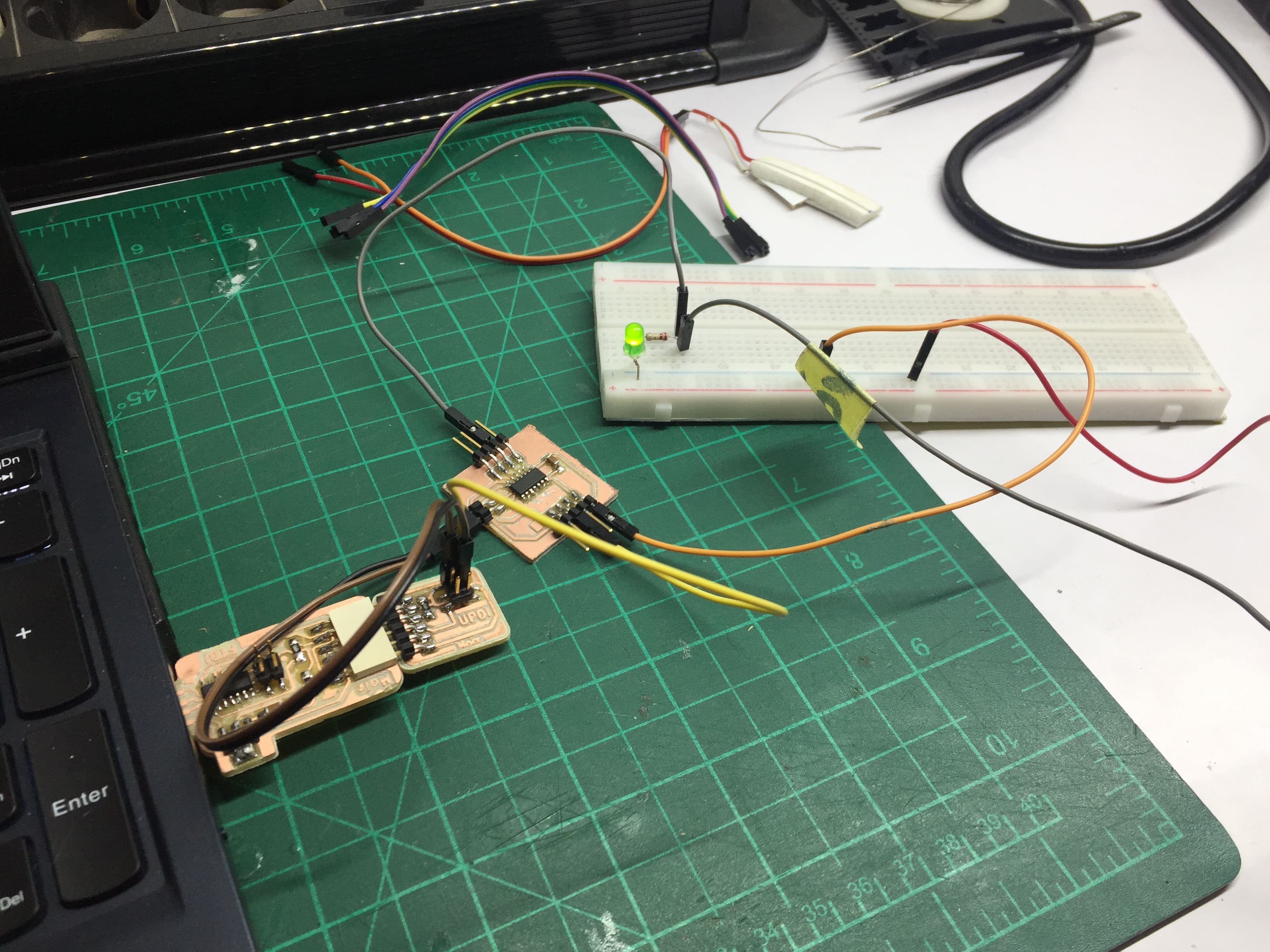
Simple circuit for testing the Oscilloscope
Then we started by connected the probes of the oscilloscope to our circuit, by connecting the passive probe to the GND of the circuit and the active probe to the positive pole of the LED.
So by changing the PWM we will find that the signal shown on the oscilloscope is changing accordingly.
PWM changing and finding that on the oscilloscope
Individual Assignment
In this assignment we need to redesign the Echo hello-world board and add some components to it. So follow the steps to see what I have done.
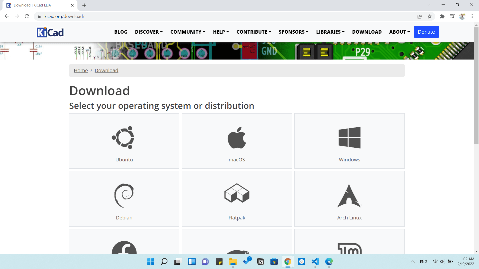
PCB design on KiCAD
First we need to download KiCAD, and it's free to download.
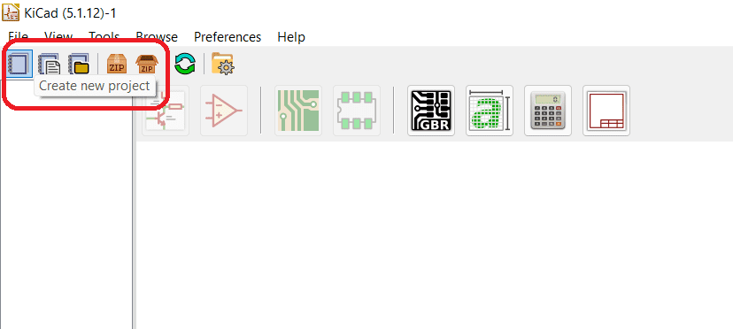
Then we want to make a new project by clicking on New project and saving th project somewhere and giving it a name.
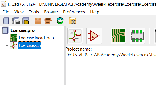
Then we will start making the Schematic by clicking on the schematic file on the left as shown
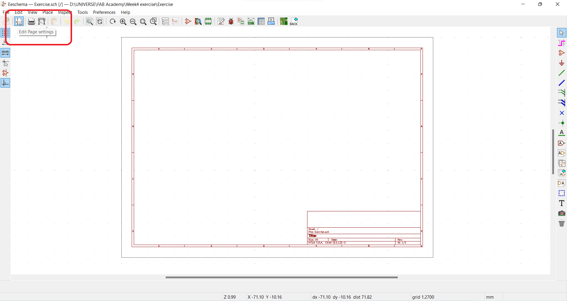
Then a new schematic will appear and we can start by editing the page settings found above to edit the page's size and table content.
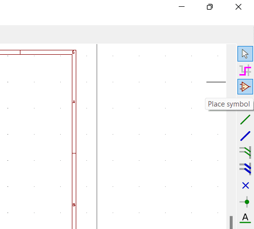
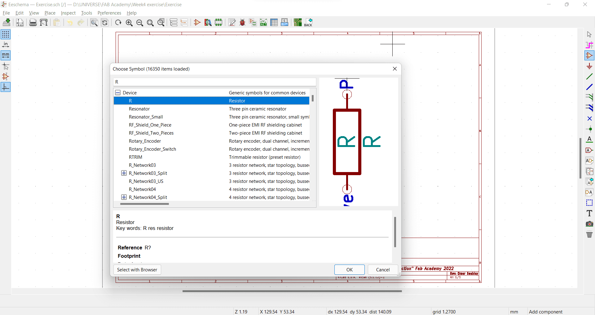
Now we want to place some components by clicking on the Place symbol icon as shown and Left click on the sheet anywhere to open all Components installed.
Then I can search for any component I need and put in my schematic. So here I am looking for a resistor and found one called R which is commonly used as a resistor.
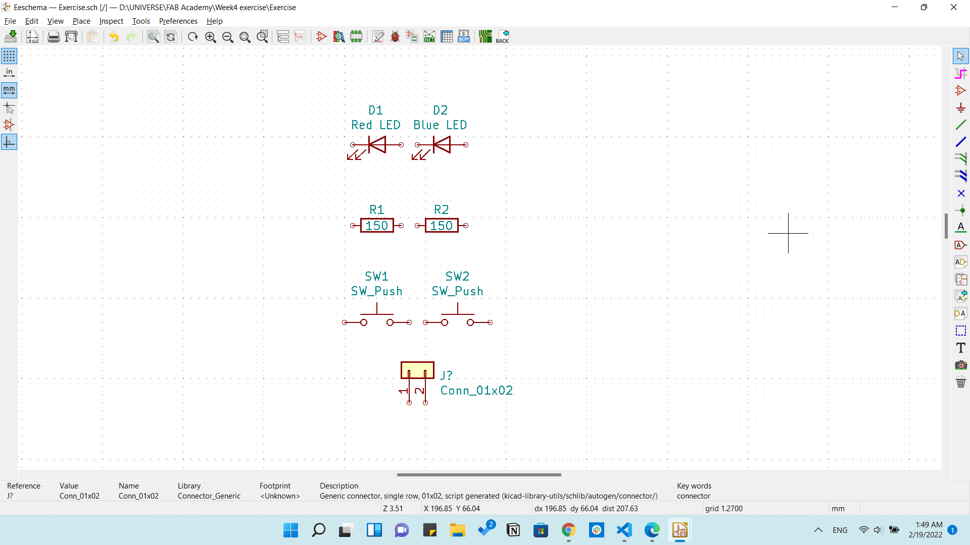
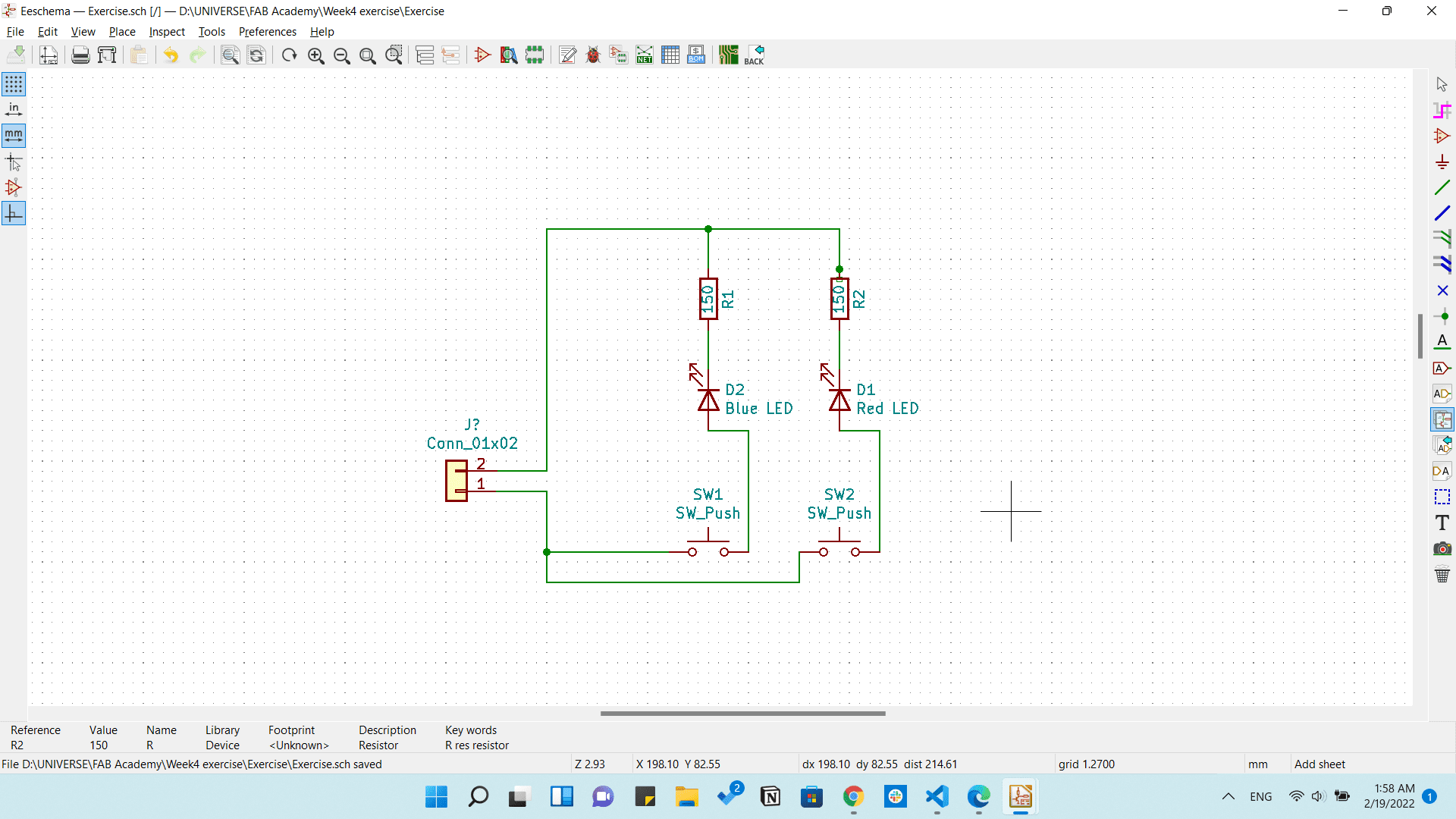
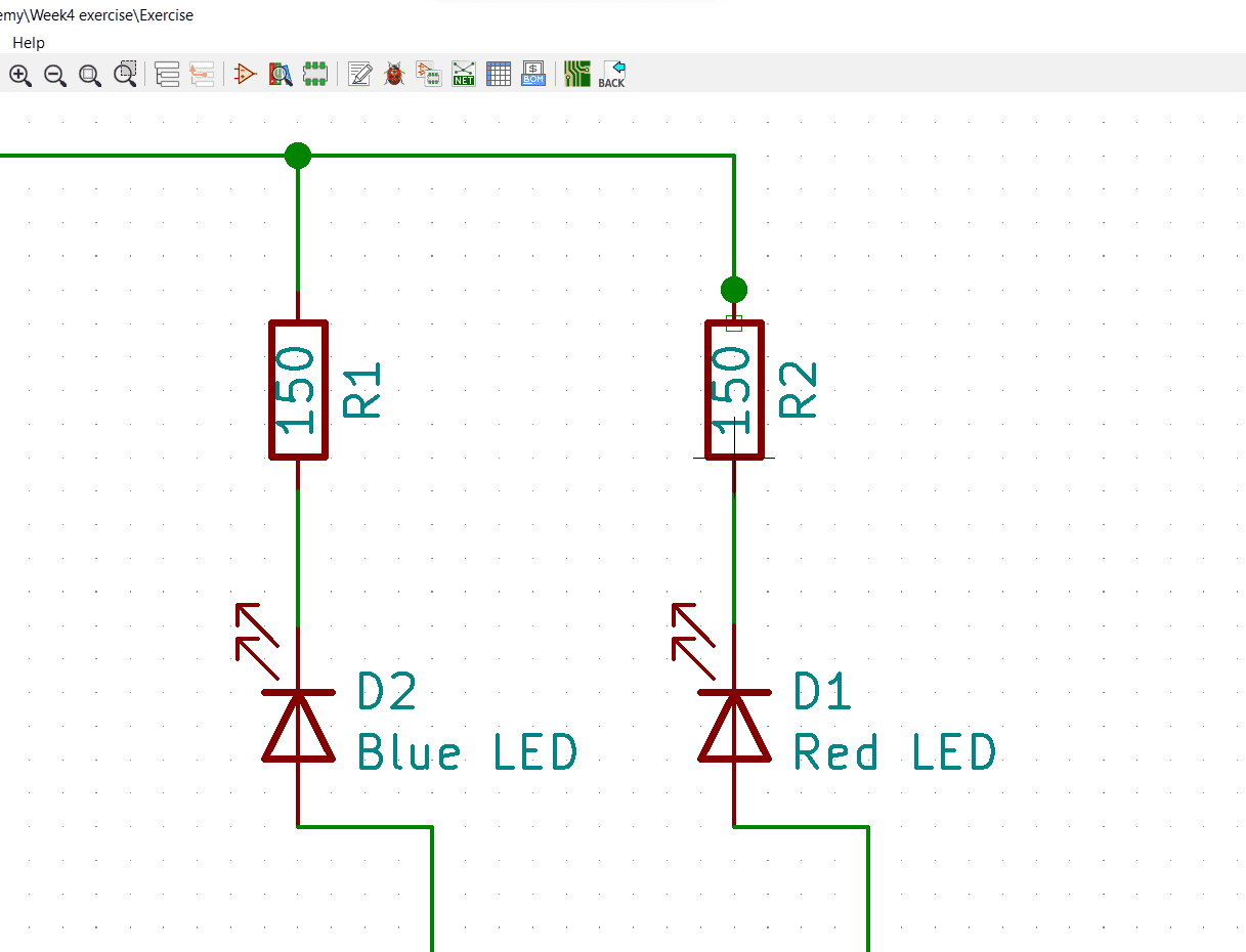
Then after designing a simple schematic consisting of 2 LEDs and 2 Switches connected to a 5v power input through resistors as shown.
Then we need to make the connectins of the components using wires so we will click on the Place wire icon on the left.
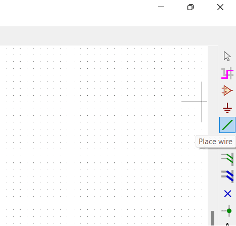
Then we will just click on any component's tip and click on the other one we need to connect to and it will draw a line between them.
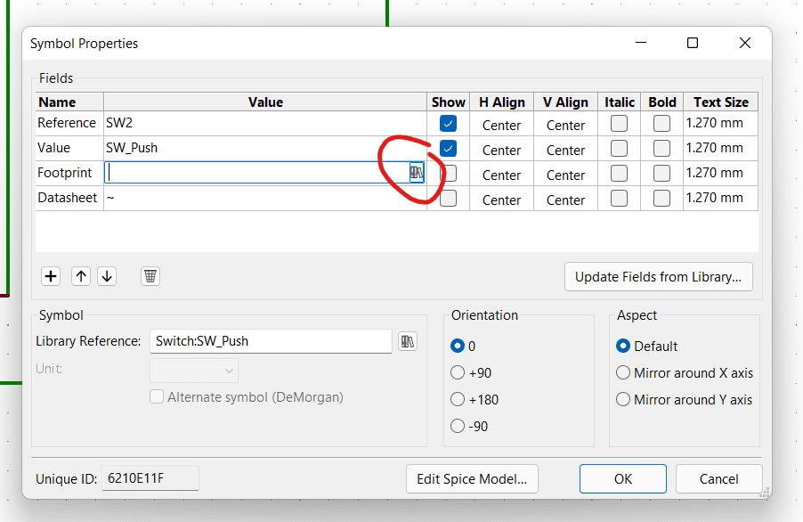
Then we need to add a footprint for each component to apply that in the PCB design. So we will just move the cursor to the component we need to add the footprint to and press E and thet will open a Symbol properties that allows us to add the footprint and edit some parameters we need.
Now we will add the library to the component by clicking on the book's icon on the footprint value.
And we will chose which component we need to add.
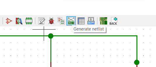
The we need to make our PCB design so first you need to generate a Netlist from the schematic we made to import it in the PCB design. and you can find it in the top tools bar as shown and save it in the same folder.
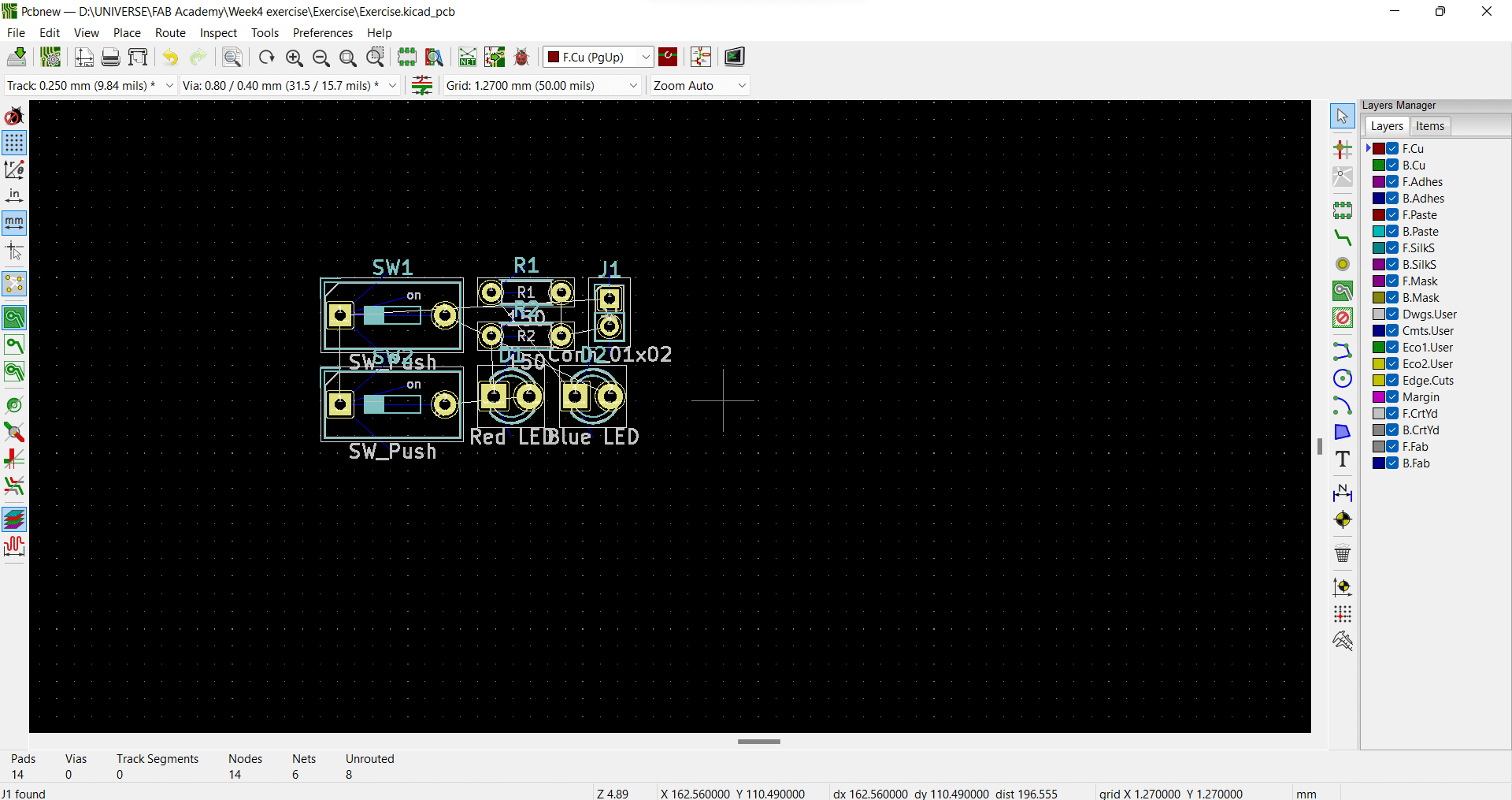
Then we will open the PCB editor and import our netlist we just created from the tool menu shown. And press on Update PCB.
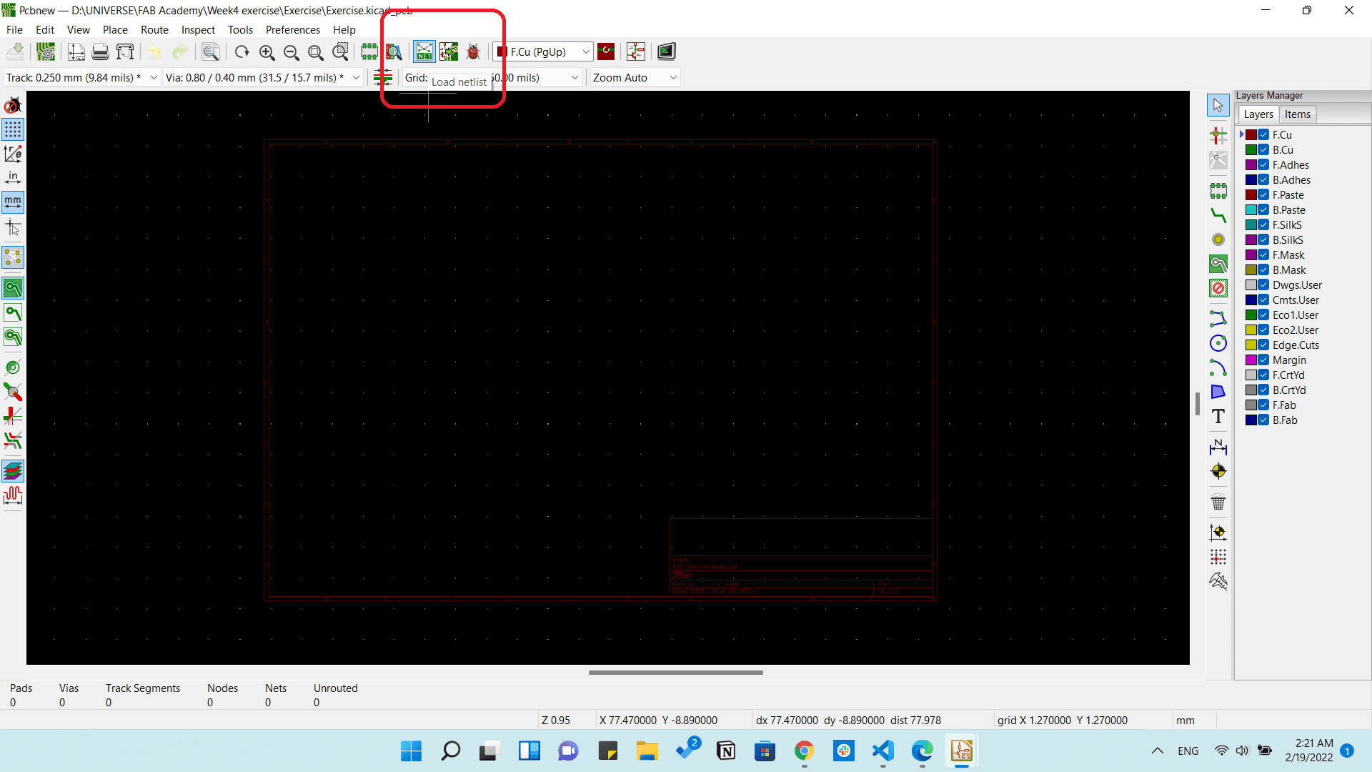
And this is what we will have.
You can follow this tutorial from John's Basement like I did and it was really helpful.
After that excersice I wanted to redesign the Echo hello-world so you can find the schematic under the Attiny44 section from here and I will be adding just a LED, Push button and a Resistor.
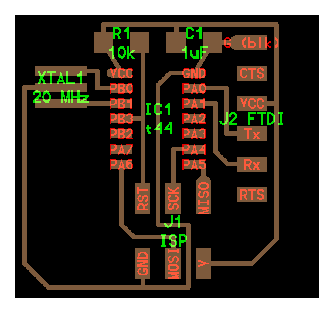
Echo hello-world board
The following is the BOM I used in the board.
| Name | Datasheet | Quantity |
|---|---|---|
| ATTINY44A-SSU-ND | Attiny44 | 1 |
| Headers & Wire Housings 6P | 95278-801A06LF | 1 |
| SMD 10 kOhms 250 mW Resistor | RC1206FR-0710KL | 1 |
| SMD 1 kOhms 250 mW Resistor | RC1206FR-071KL | 1 |
| SMD 0 Ohms 250 mW Resistor | RC1206JR-070RL | 1 |
| CERAMIC RES 20.0000MHZ 15PF SMD | ECS-CR2-20.00-B-TR | 1 |
| Capacitor CER 1UF 50V X7R 1206 | - | 1 |
| ISP 6-pin header | 1465 | 1 |
| Push button | Push button | 1 |
| SMD LED | APT3216QWF/D | 1 |
Then I made the Schematic of the edited board as following and called it Vengeance.
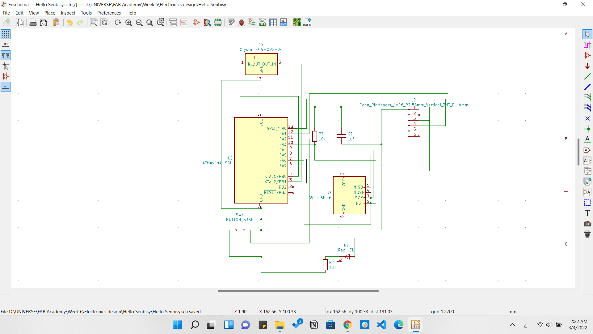
Vengeance schematic
And I wanted to make a different outline, so I googles a batman outline and downloaded that image and imported it to inkscape to trace it and export it as svg.
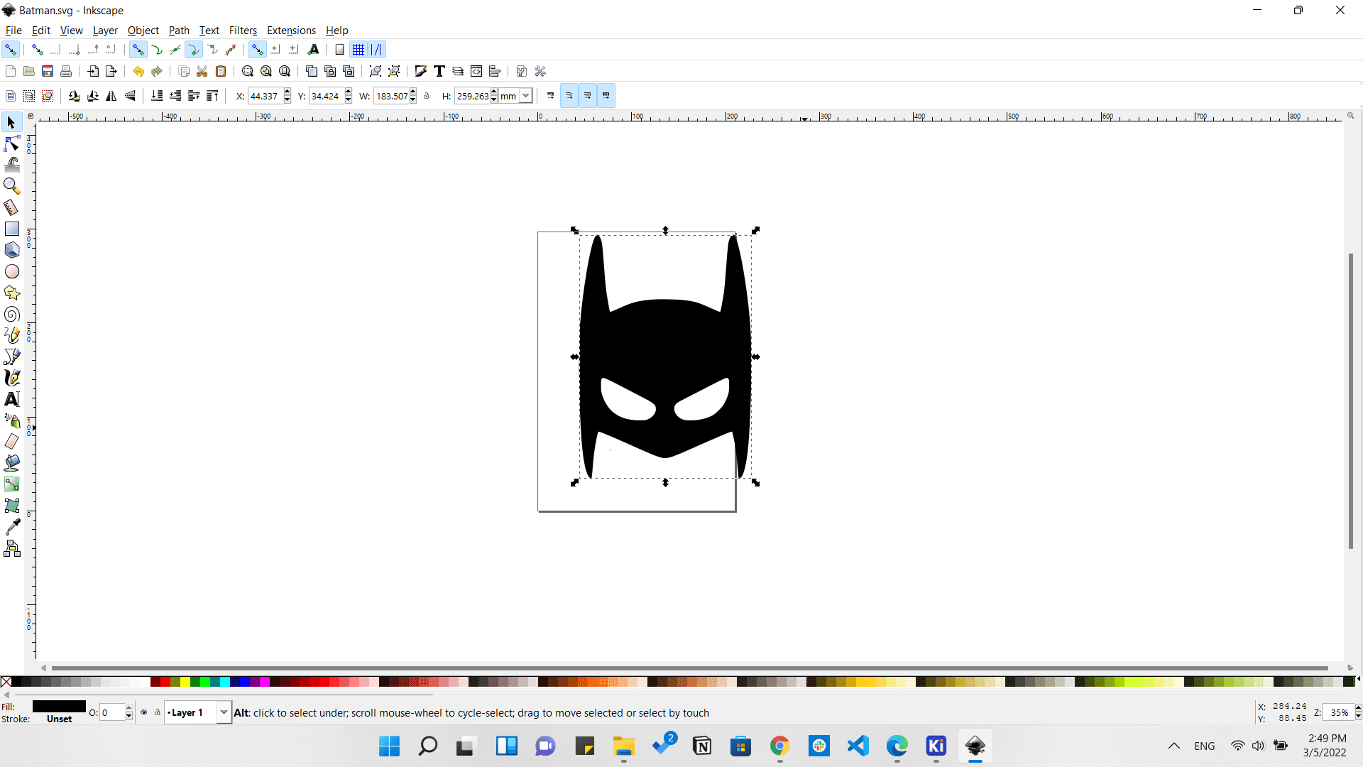
Batman's outline in Inkscape
Importing the outline as Edge cuts.
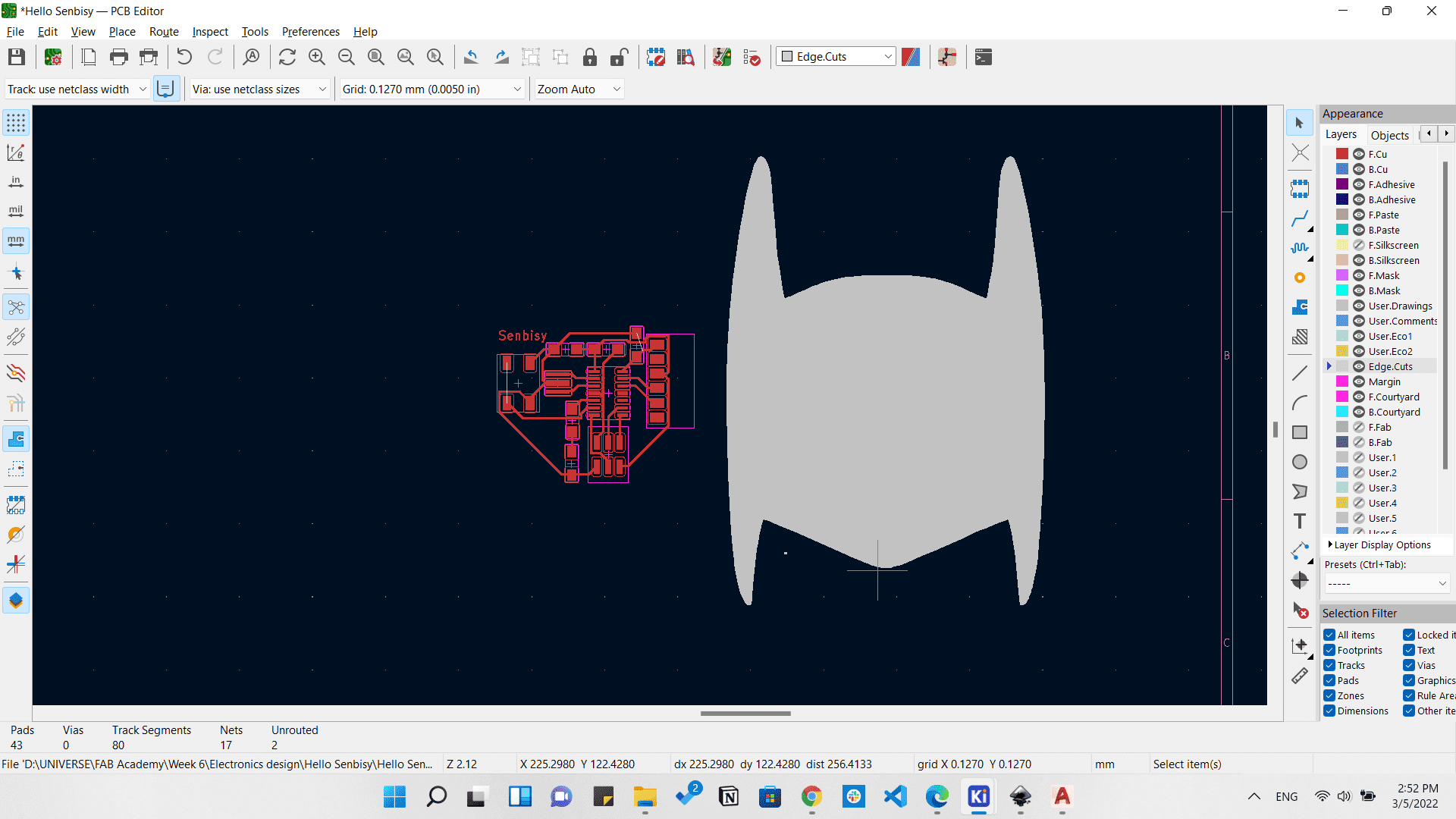
Batman's outline in Inkscape
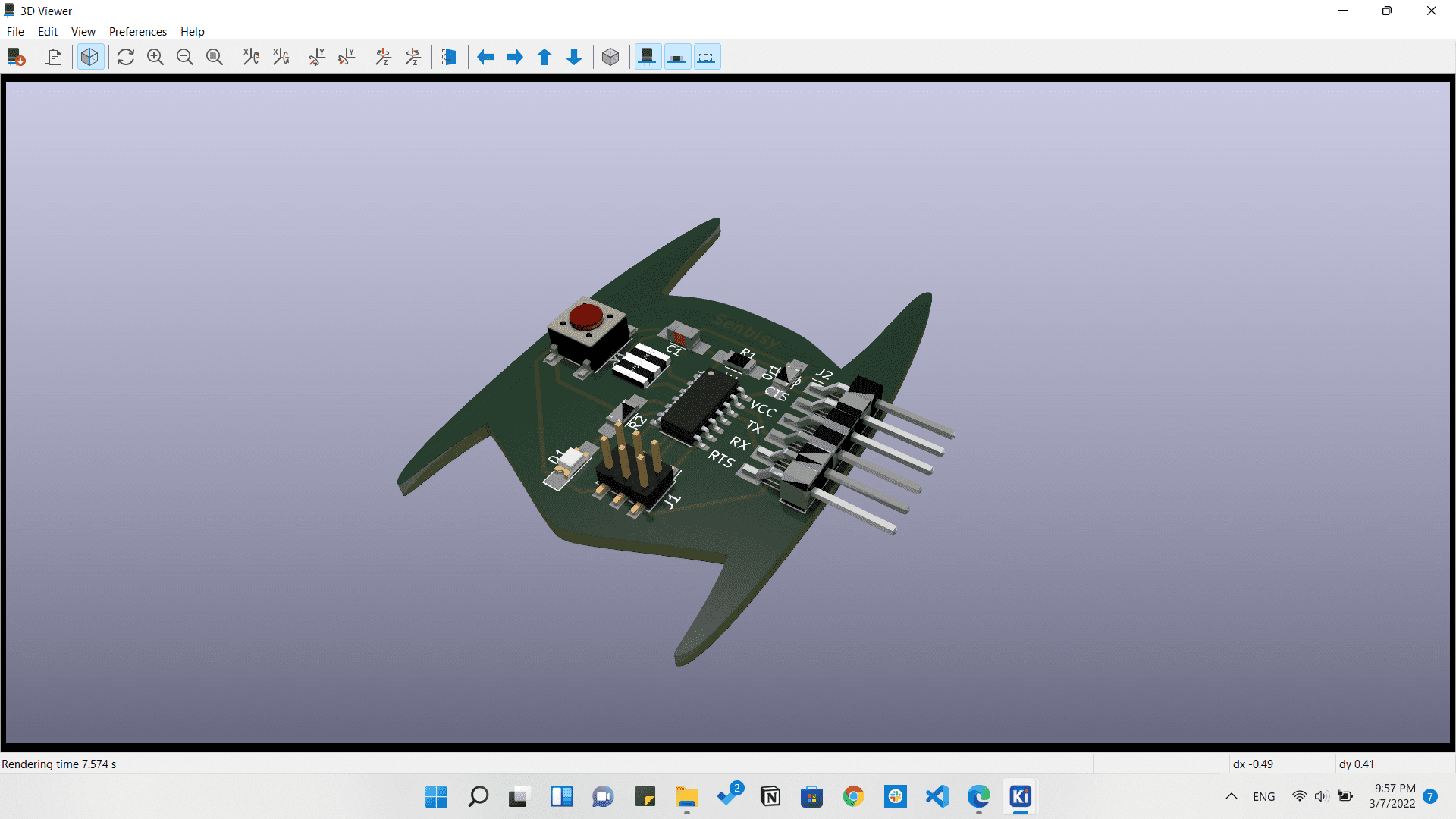
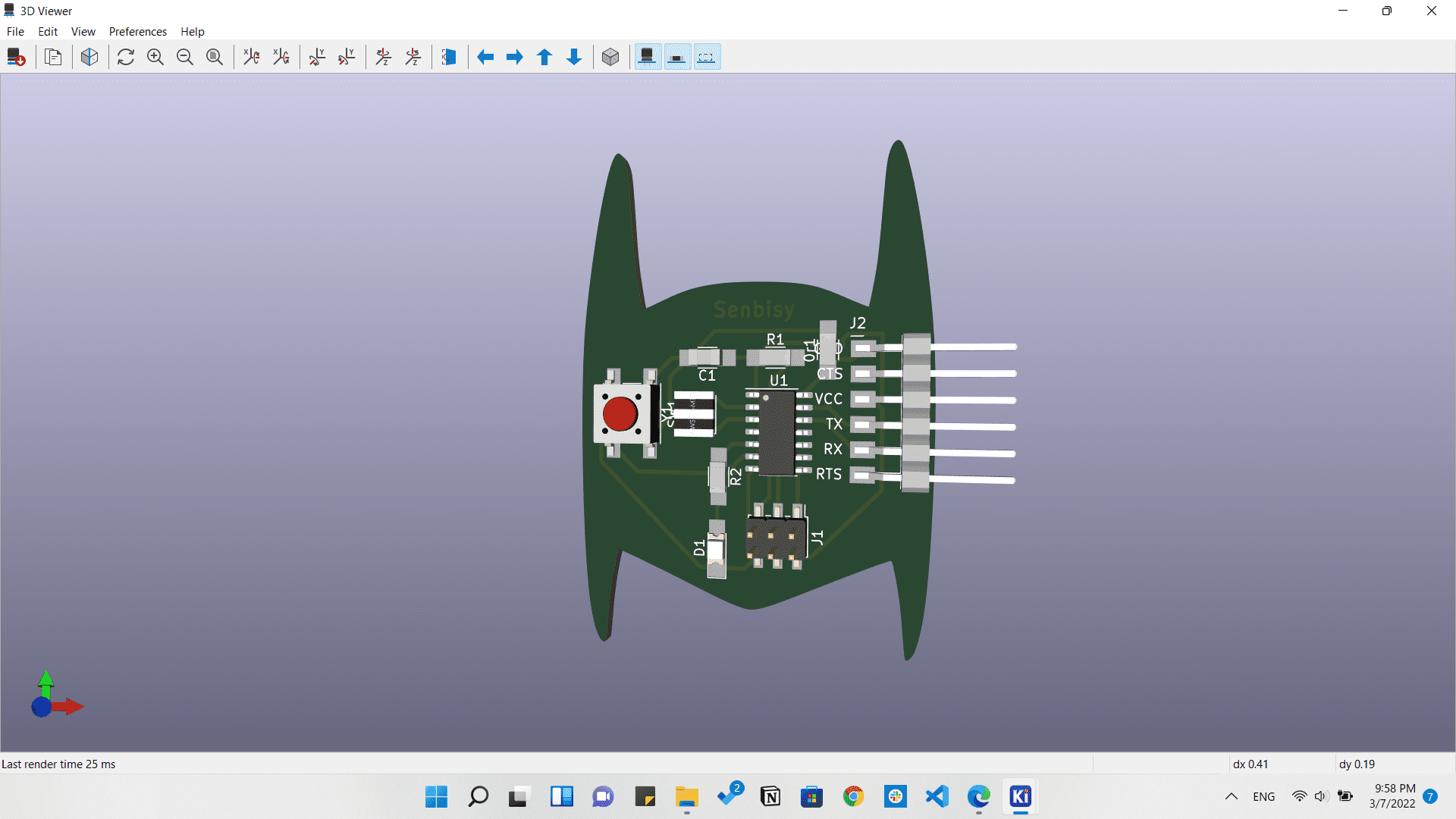
And from the 3D viewer we can se a 3D view of our vengeance board.
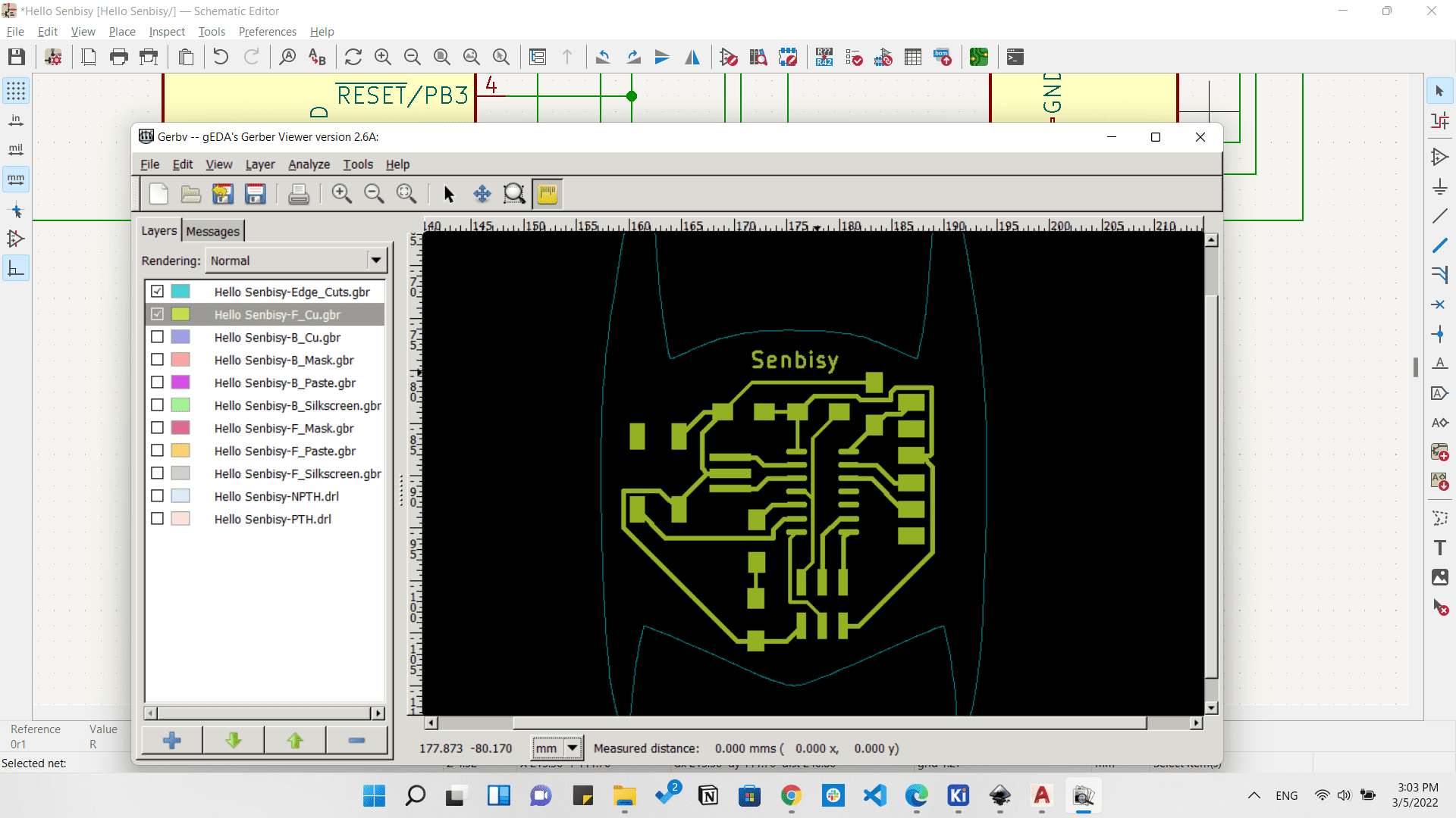
Exporting Gerber files from File > Fabrication Outputs > Gerbers.
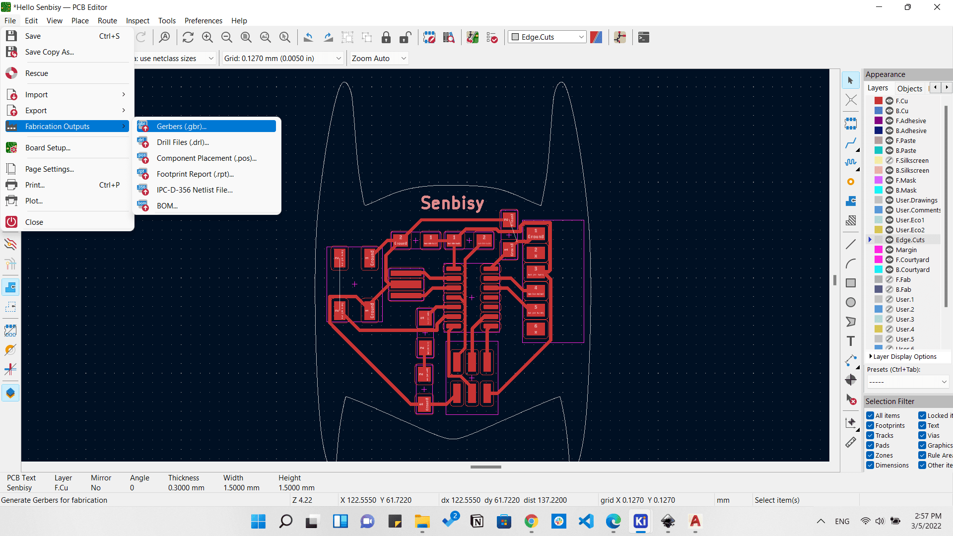
Exporting Gerber files
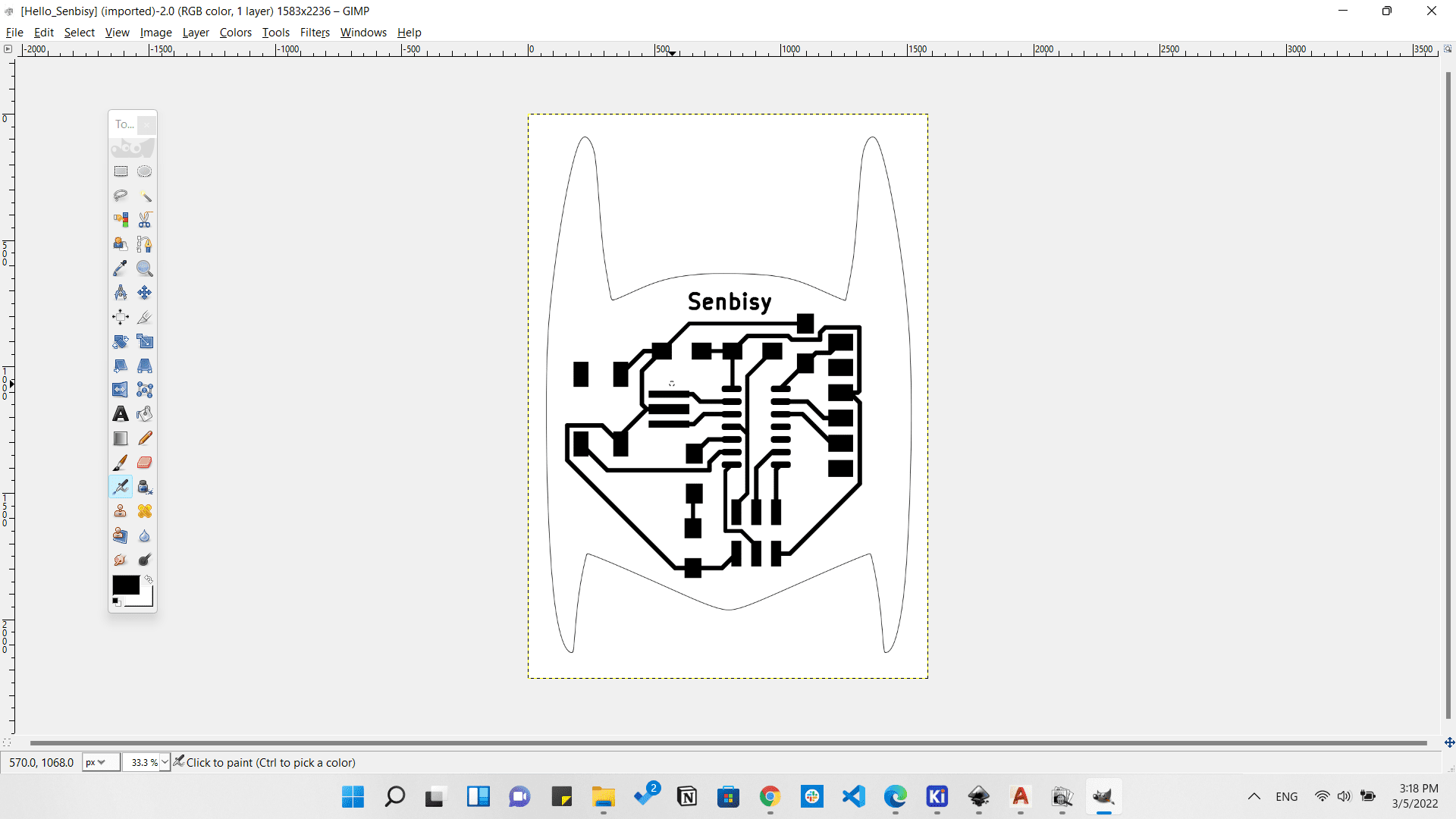
Preparing files for fabrication by Gerbv and Gimp.
Fabricating the PCB on the Modella machine.
Fabricating the Vengeance board on the Modella
Preparing all components.
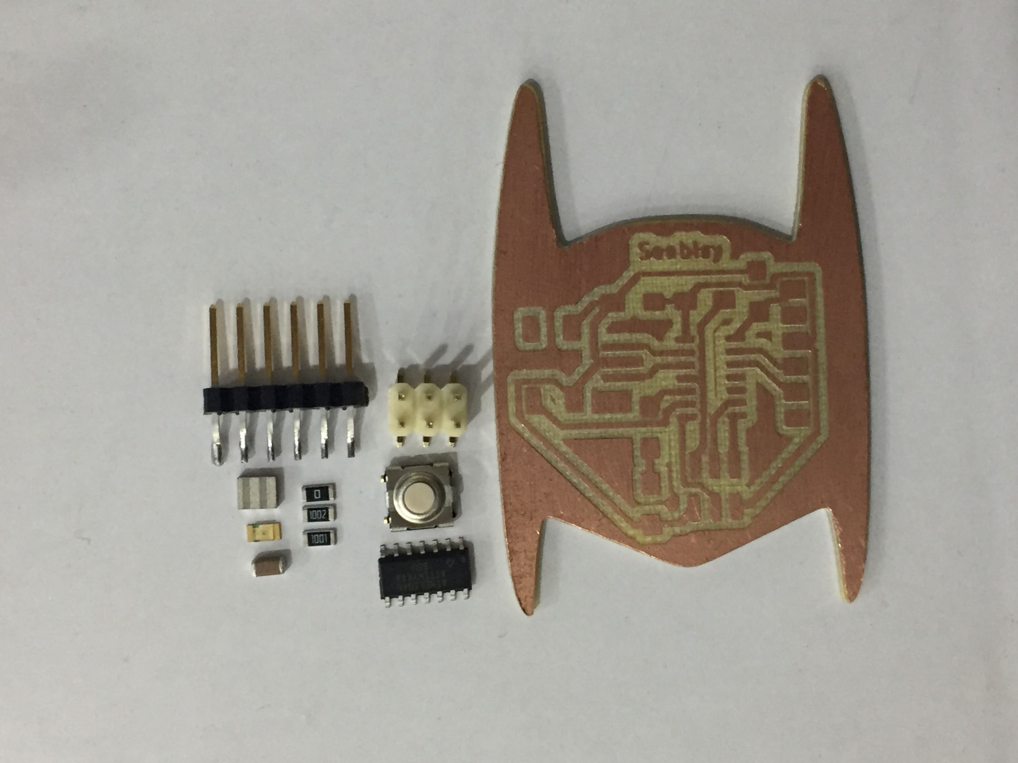
Vengeance board with components
Soldering the components.
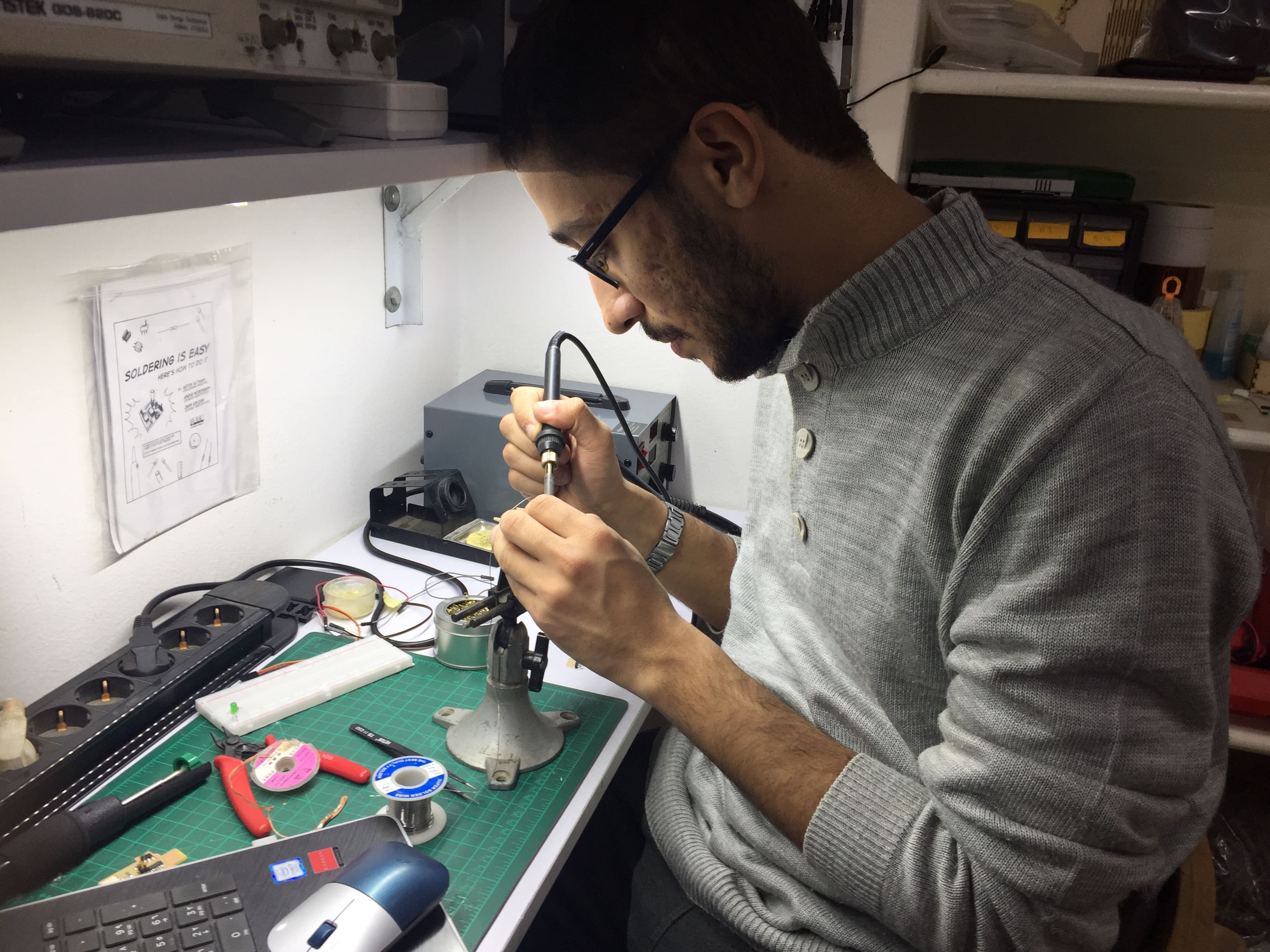
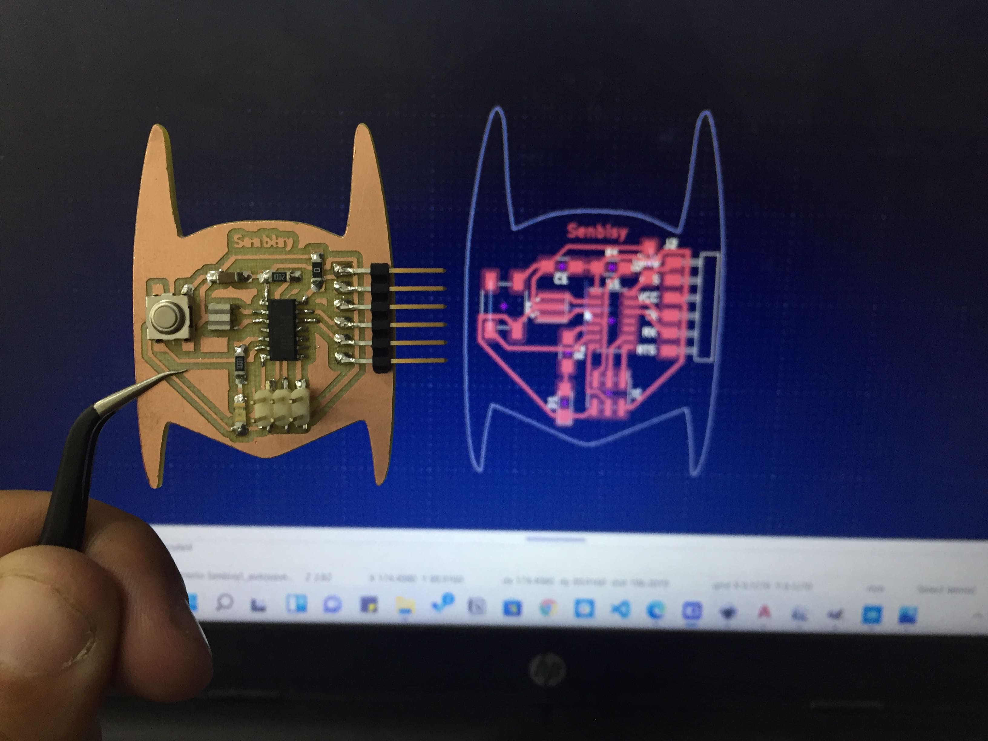

I Am Vengeance
Programming
In this week we are going to type in the Neil's code so I just followed the steps he made in order to test my board
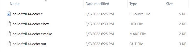
So by following these codes here, we will fing that we just need to copy the echo.c and echo.c.make codes and save them in a folder at our computer.
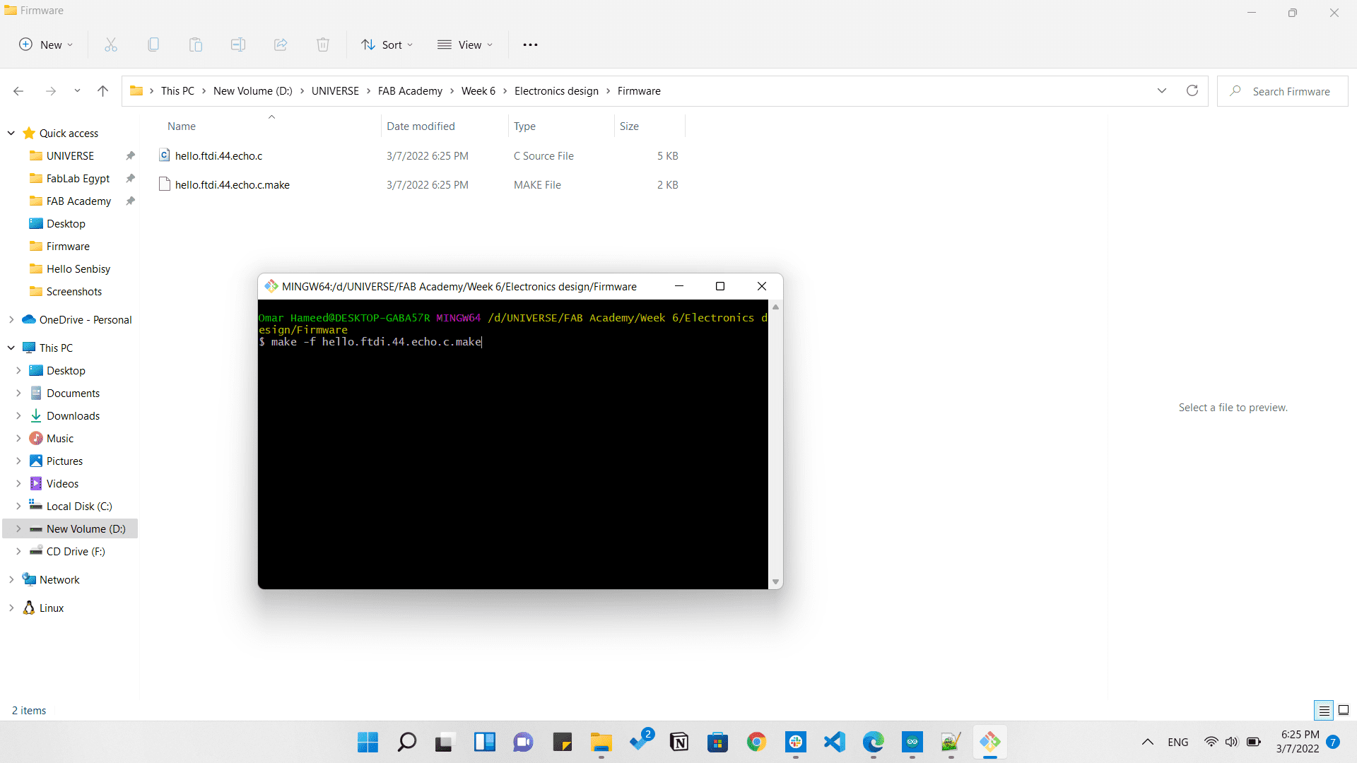
Then we will open a Git bash in the same folder we saved those codes and type the codes we have earlier.
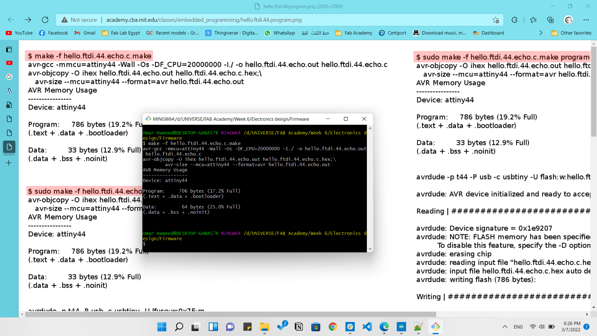
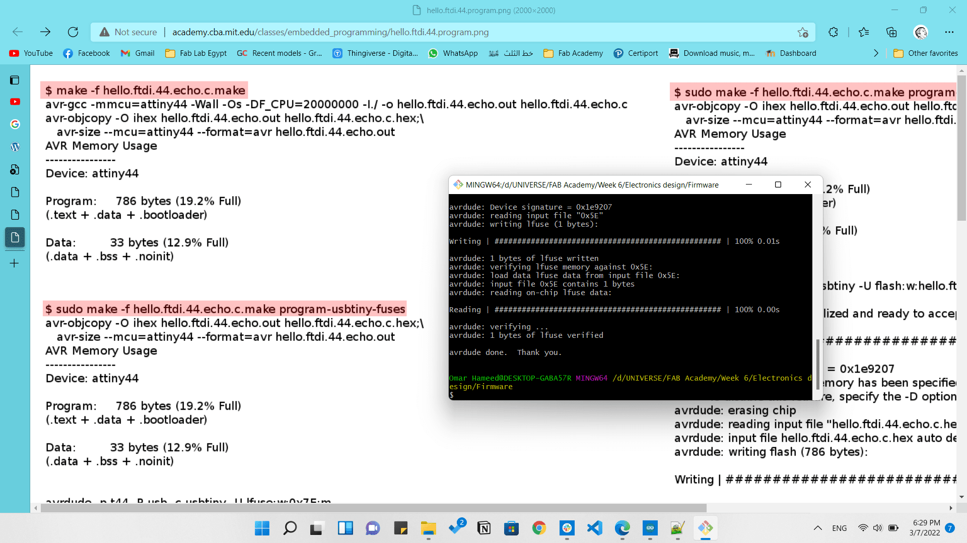
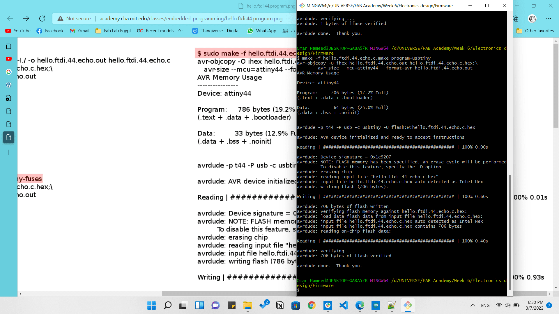
After that will appear to us the results that we have in the link provided. That means every thing is working perfectly, we just need to test it.
So we will open Arduino IDE and open the Serial Monitor and type anything in it and see the results.

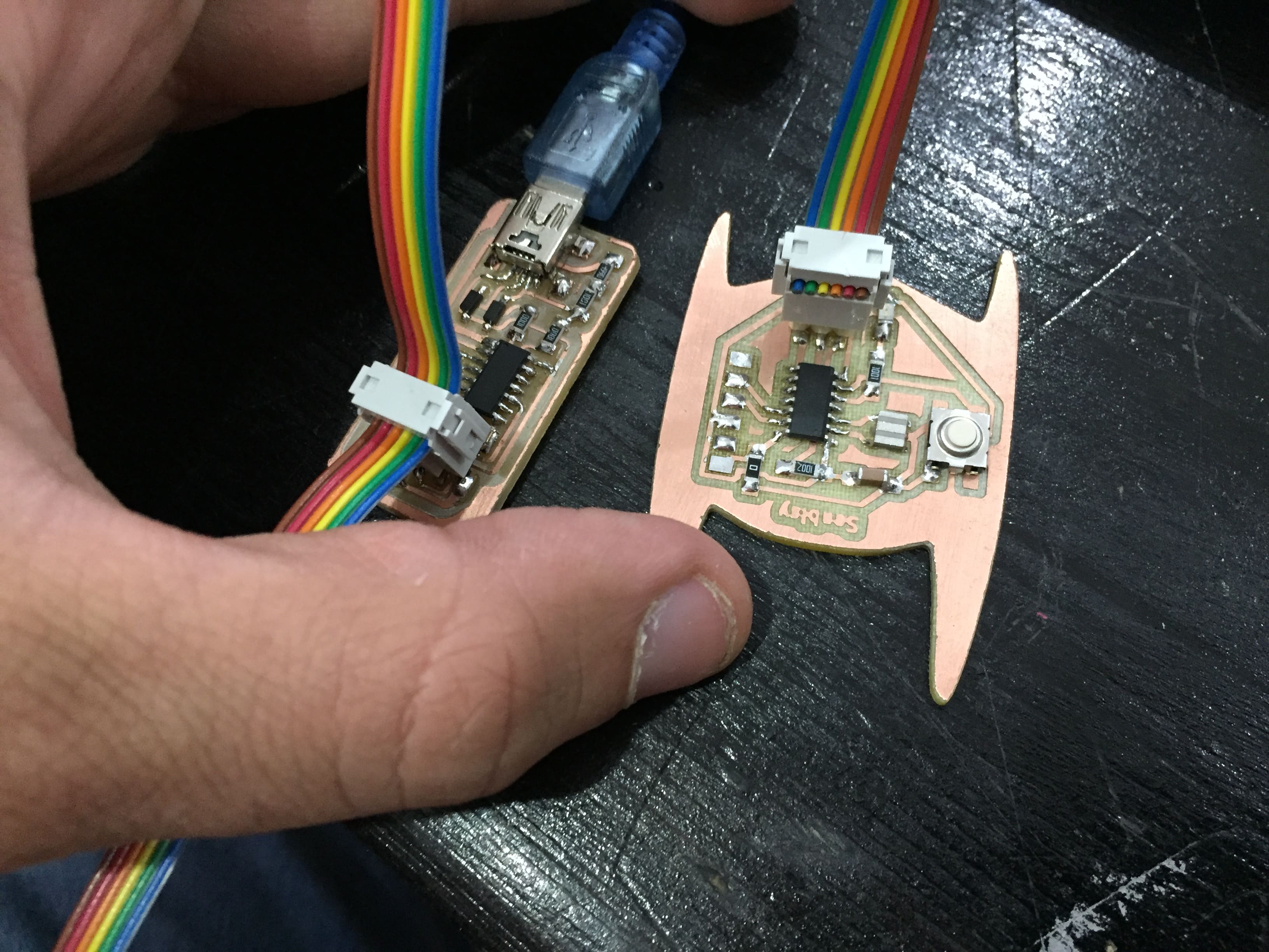
Now all what is left is to type a code and test the LED and push button we added and connect the FabISP with the vengeance board.
So I just typed a simple code to test the LED as follows:
#define switch1 7
	#define led1 8

	void setup(){
	  pinMode(led1,OUTPUT);
	  pinMode(switch1,INPUT_PULLUP);
	}
	void loop(){
	  int input1=digitalRead(switch1);
	  if(input1==LOW){
		digitalWrite(led1,HIGH);
		delay(100);
		digitalWrite(led1,LOW);
		delay(100);
	  }
	  else{
		digitalWrite(led1,LOW);
	  }
	}
Now we will just adjust some settings in the tools menu as the Board, Processor, Clock, and Programmer as following:
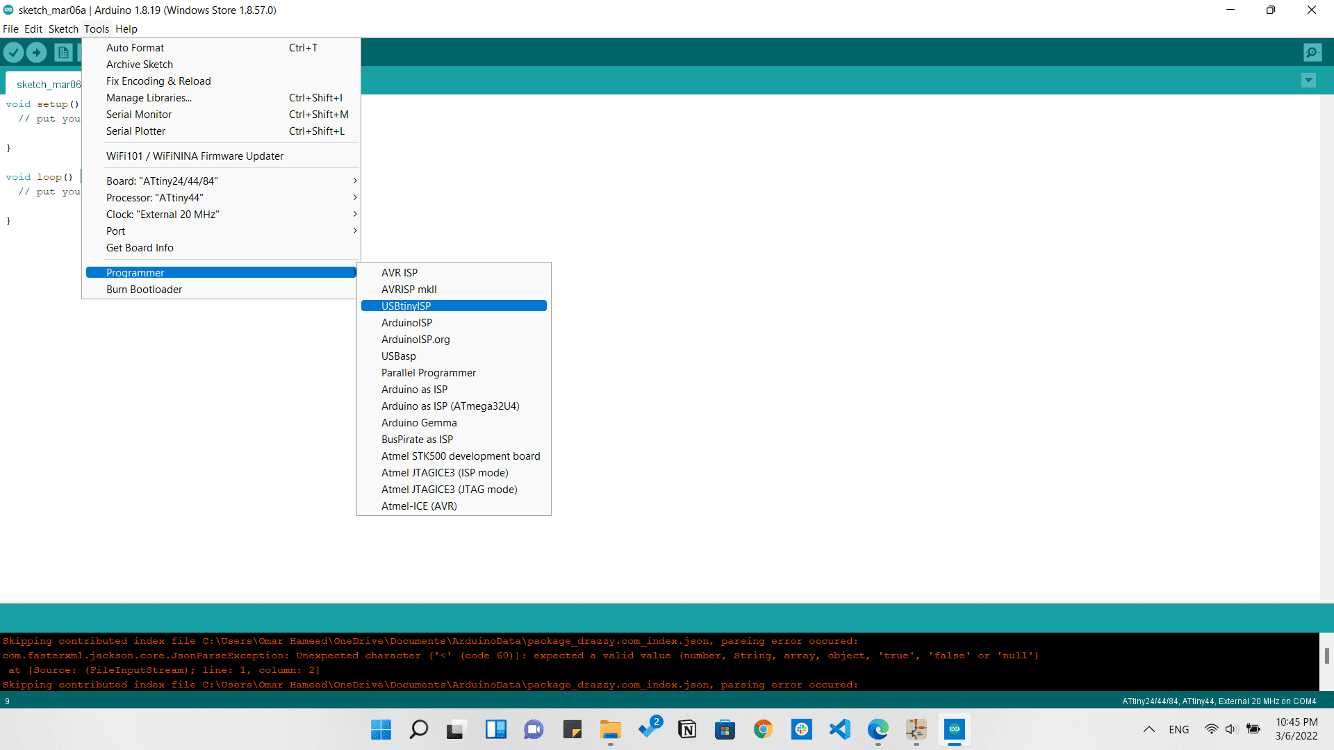
Then from sketch we will chose Upload Using Programmer
LED is blinking while pressing the push button
That's all folks!