Week 3
Computer-Controlled Cutting
In this week's assignment we had to work on the following:
- Group Assignment.
- Characterize your lasercutter's focus, power, speed, rate, kerf, joint clearance and types.
- Individual Assignment
- Cut something on the vinylcutter
- design, lasercut, and document a parametric construction kit, accounting for the lasercutter kerf, which can be assembled in multiple ways, and for extra credit include elements that aren't flat
So lets understand first how does a laser cutting machine operate, and what's meant by focus, kurf, power and other terms I'll be using here means.
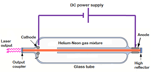
How does a CO2 LASER cutting machine works?
CO2 LASER machines usually produce the laser beam in a sealed glass tube which is filled with gas, usually carbon dioxide. A high voltage flows through the tube and reacts with the gas particles, increasing their energy, in turn producing light. Any light produced by Co2 lasers is extremely powerful compared to normal light. This is because of the mirrors that bookend the tube of gases. These mirrors reflect most of the light traveling through the tube and cause the light waves to build in intensity. The light only passes through the partially reflective mirror when it becomes bright enough. A product of such strong light is heat, heat so strong it can vapourise materials that have melting points of hundreds of °C.
Resources: HPC Laser, AP LAZER, RF Photonics Lab.
Group Assignment
In this assignment we decided to start by getting the laser machine's parameters such as focus, kurf of different materials , cutting power and speed for different materials ans thickness.A. KURF
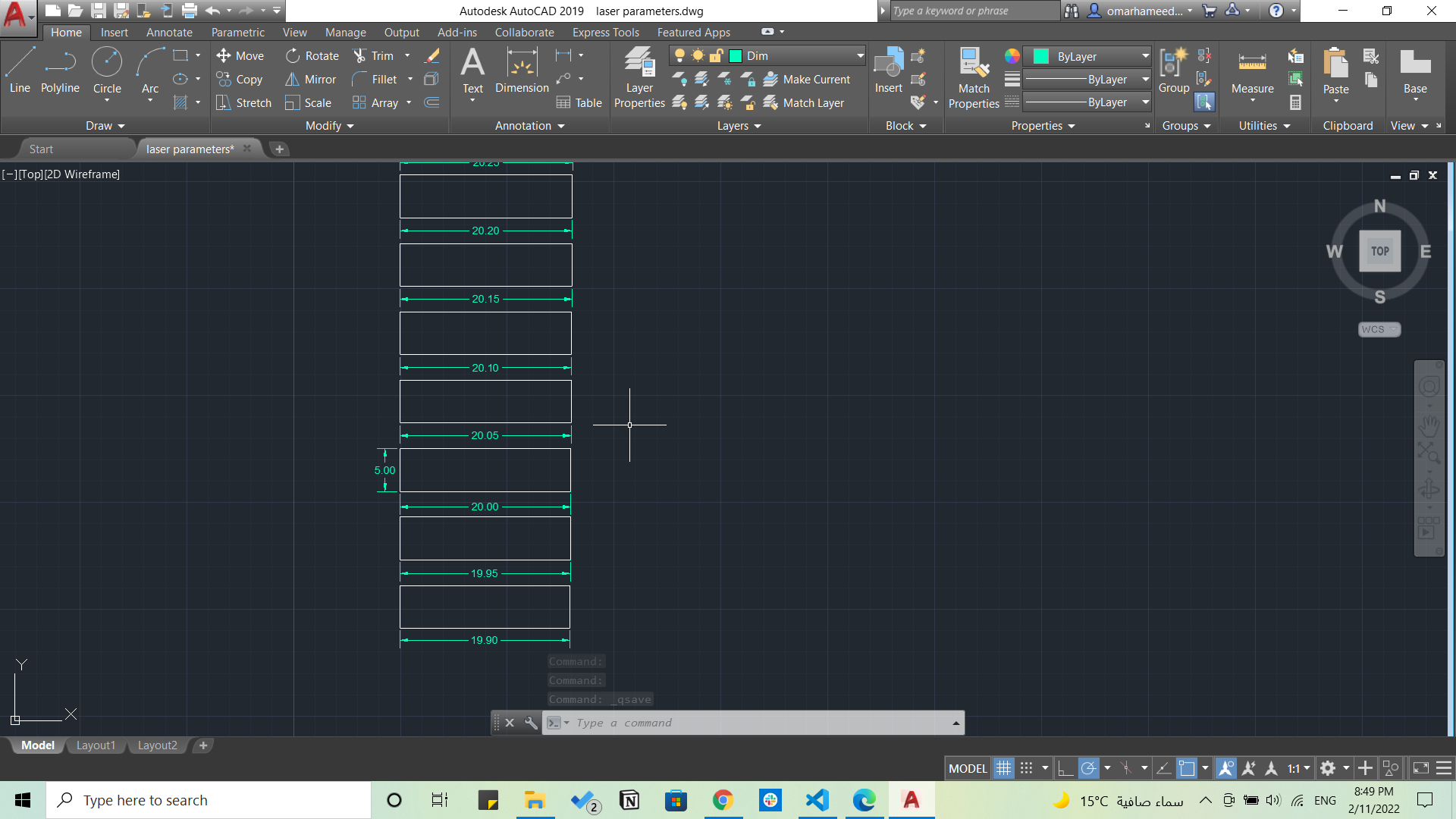
We had to draw something with different dimensions to be able to measure the kerf of the laser beam, so I designed a simple something simple having squares with 0.05mm difference starting from 19.90mm till 20.35mm using AutoCAD.
Then we started cutting it using the laser cutter as shown.
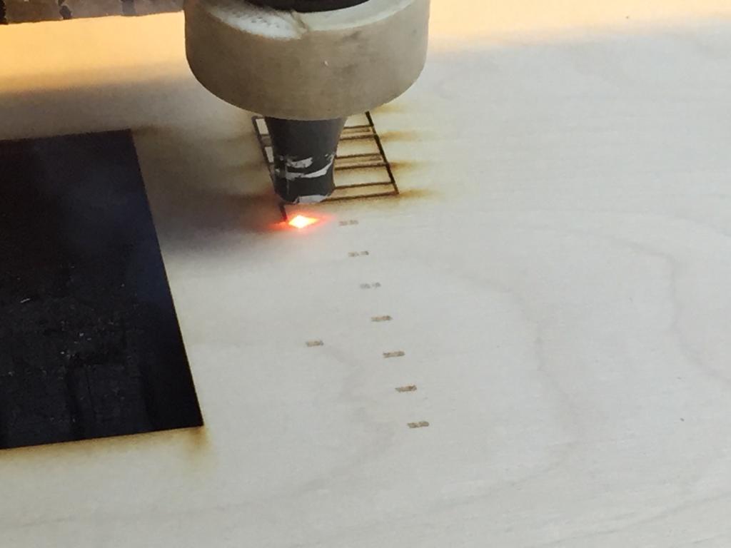
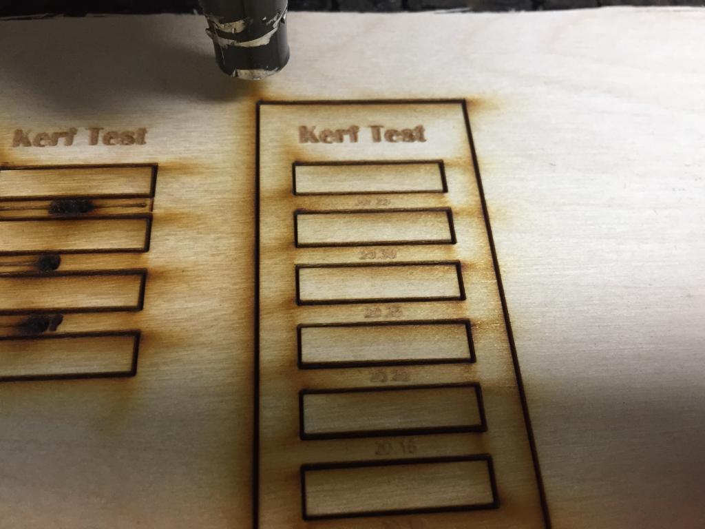
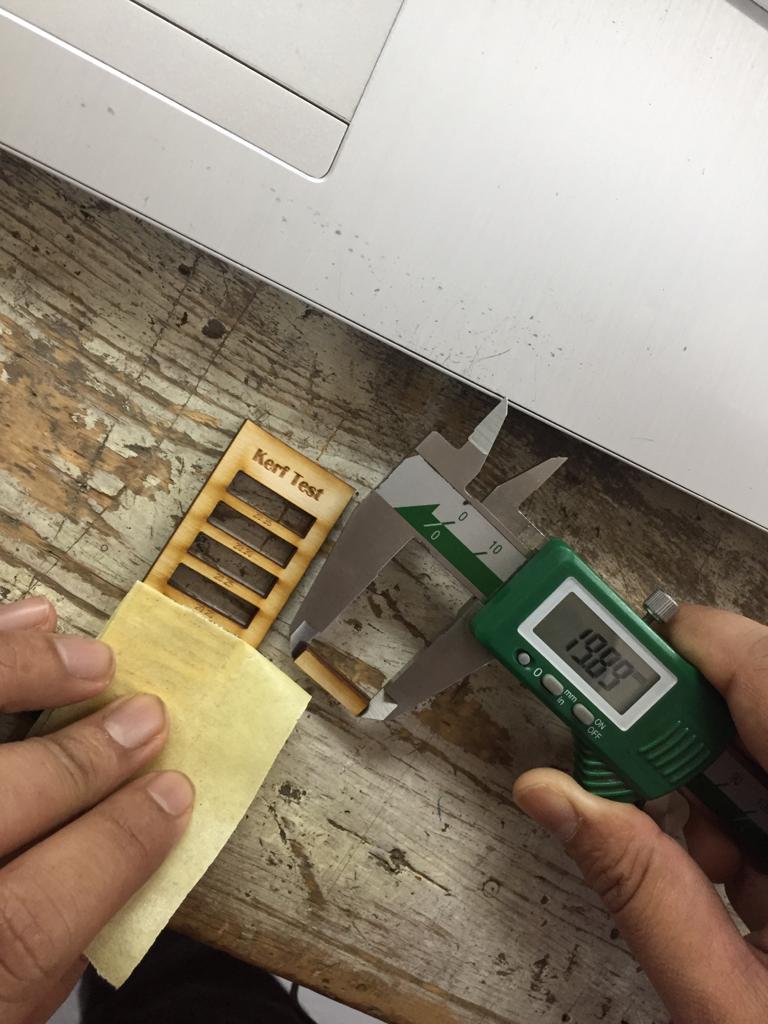
Then we measured the length of every rectancle we cut with a Vernier Calliper, to find out the kerf's distance. And we came out with a wide range or kerf and took their average to finally get it as 0.2mm for 3mm plywood.
B. POWER & SPEED
Then we needed also to come up with the different speeds and power needed for cutting different materials, so we made also these squares for testing different speeds and powers on different materials starting from 3mm plywood.
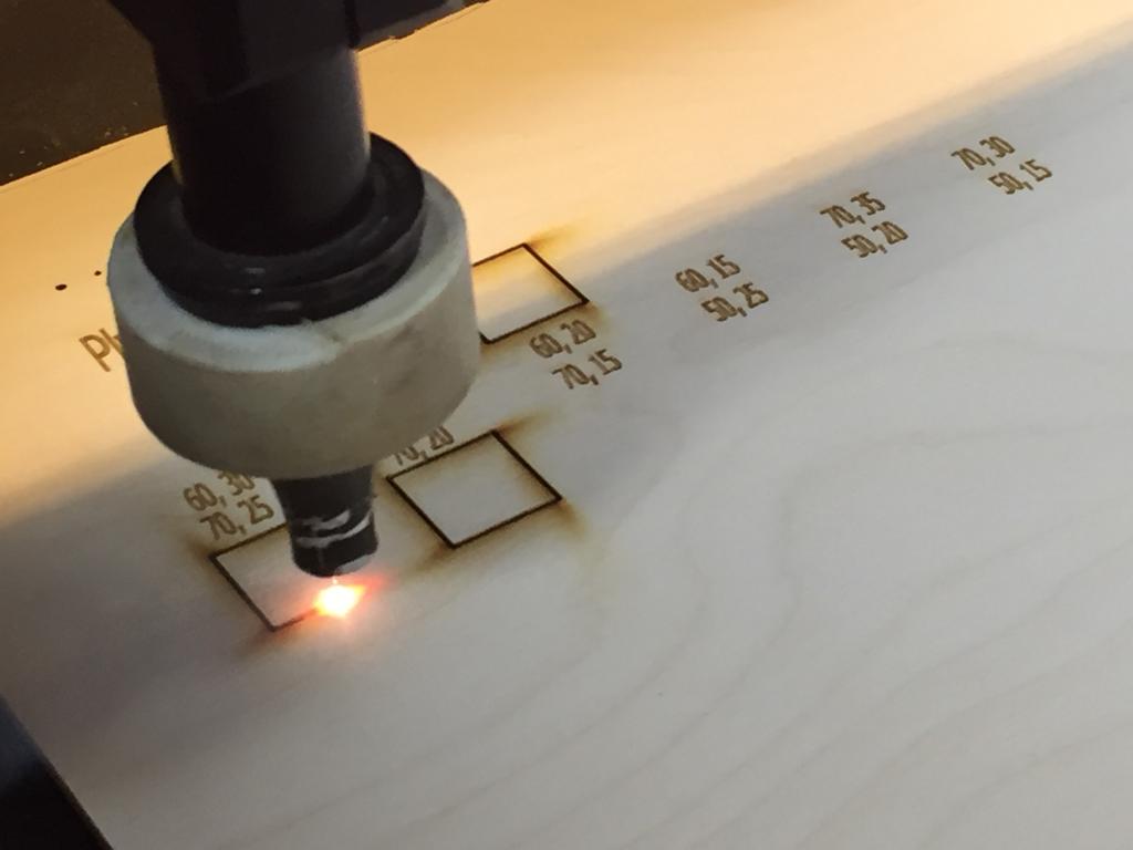
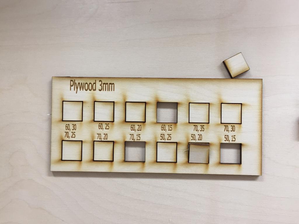
And we saw that with Speed:15, and Power: 50,60,70 the plywood can be cut easily so we set that as the cutting speed and power for 3mm plywood.
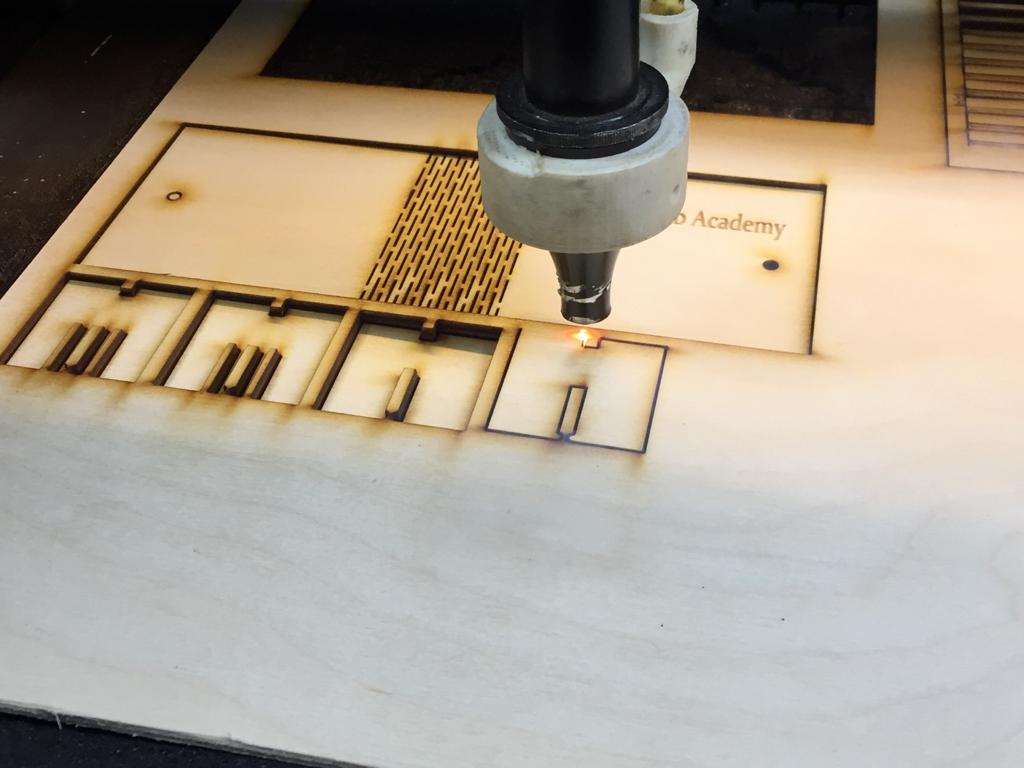
C. Focus
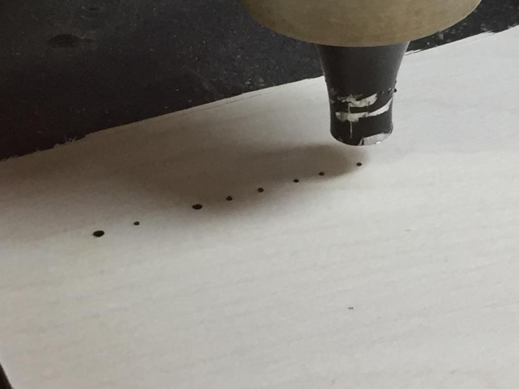
Setting the focus was bit a challenge as we had to increase and decrease the distance between the laser head and the material we are cutting on several times to know which of the pulses we made is the smallest point as the focal length must be set to the smallest dot possible made.
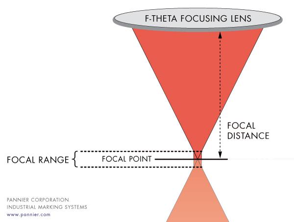
And as we see here, the laser beam is collected by the lens to be concentrated at a tiny spot which is suitable for cutting, and if we made it higher or lower than that it will require higher power or less speed to cut and the kerf will be wider.
And we found thet the suitable distance is around 6.5mm from the nozzle's end till the material.
Resources: Pannier.com,
Exercise
After doing all those tests and measurements, we wanted to apply this on a laptop stand parametric design. So I made a parametric design using SolidWorks.
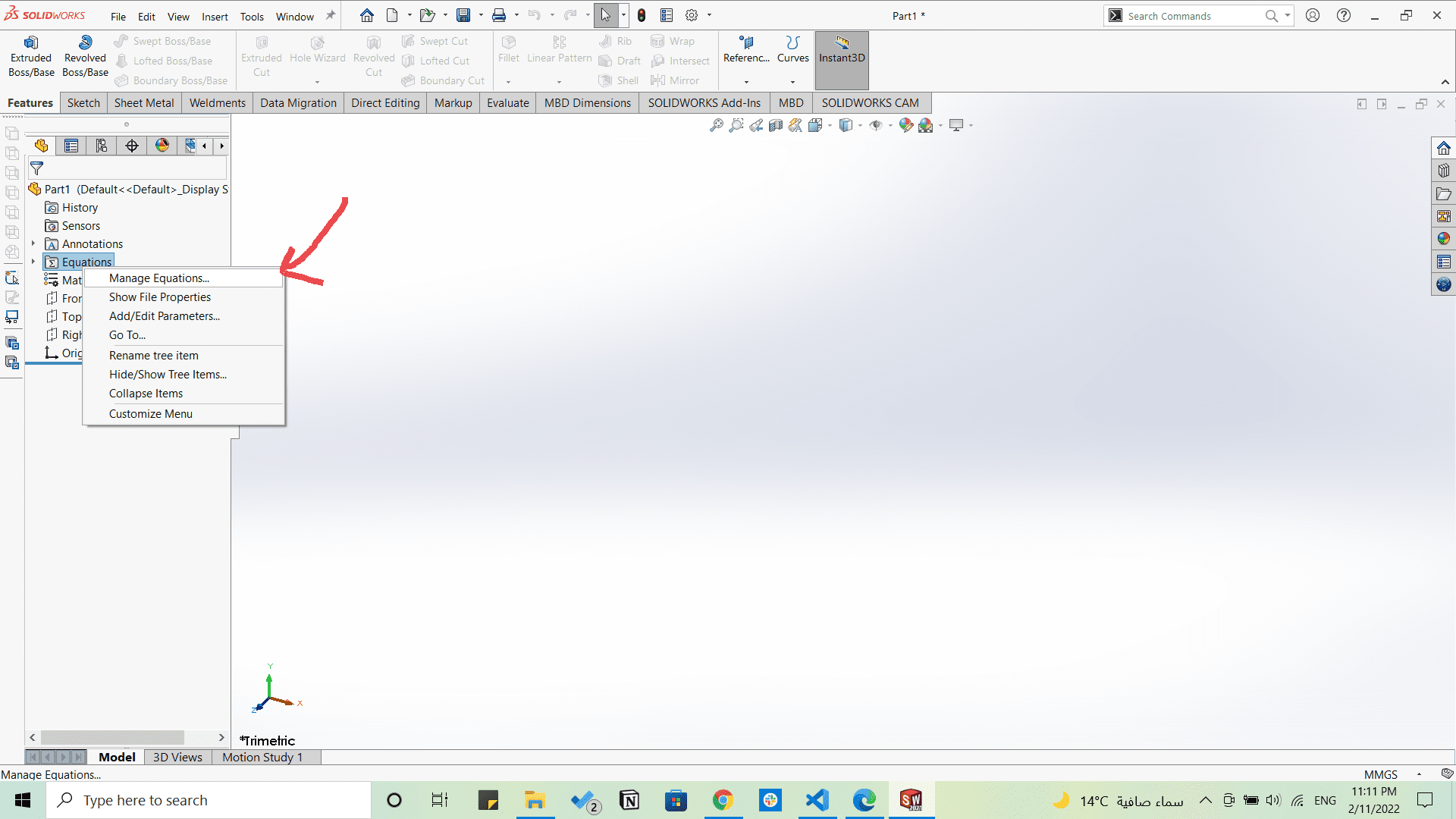
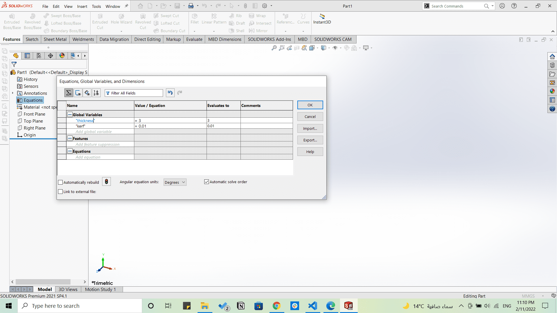
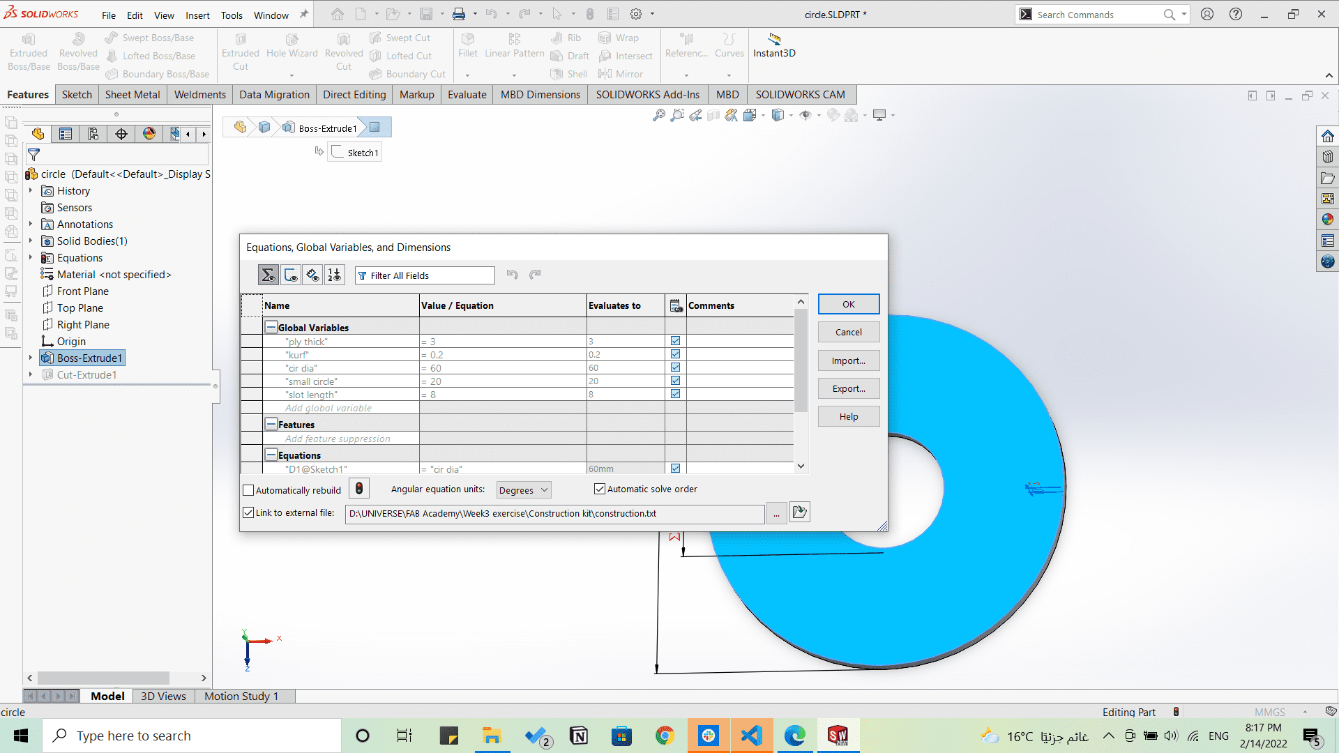
I started designing on Solidworks first by adding Global Variables by right clicking on Equations on the left tree and clicking on Manage equations for thickness and kerf and gave them initial values.
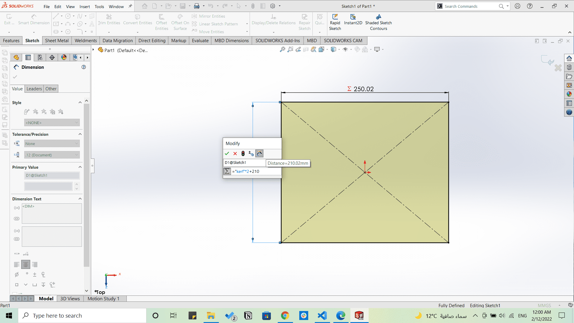
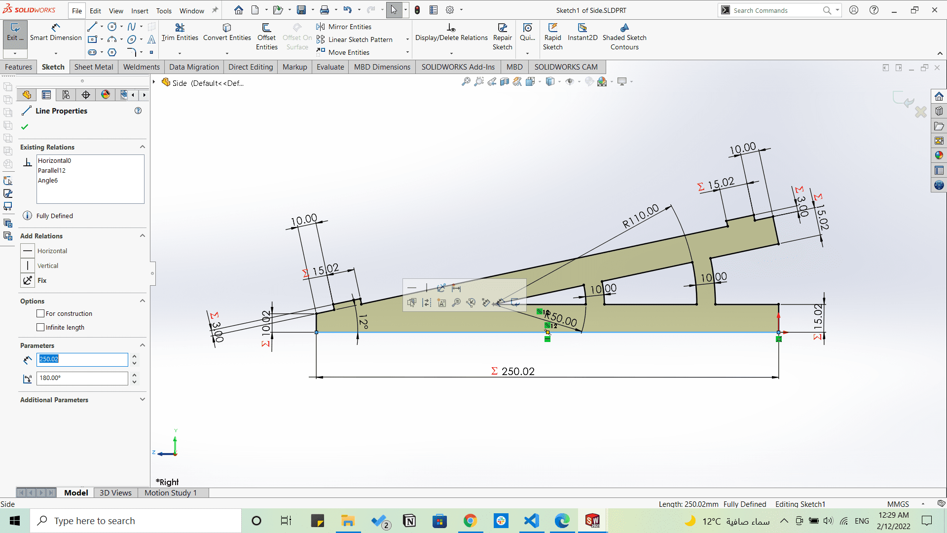
Then I started applying them in all sketches.
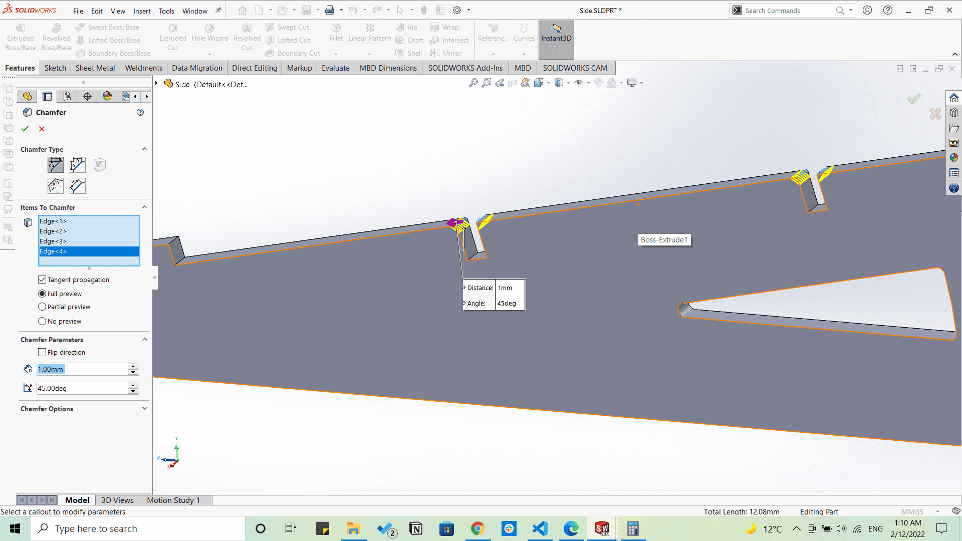
Adding some chamfers to the fits.
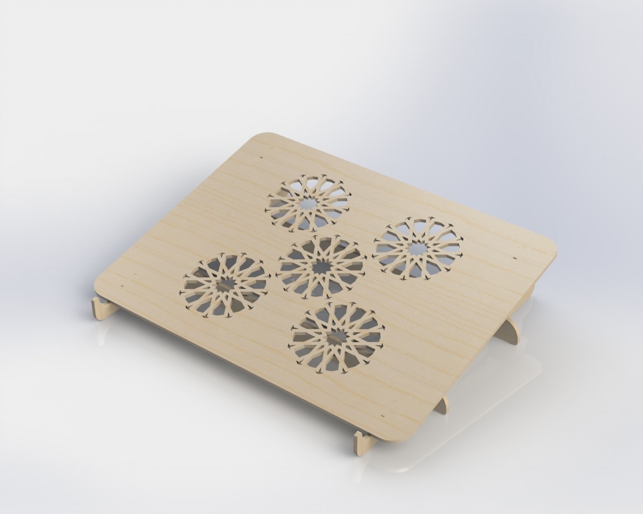
Till I made the whole design parametric, adding some wooden appearances and rendering the isometric.
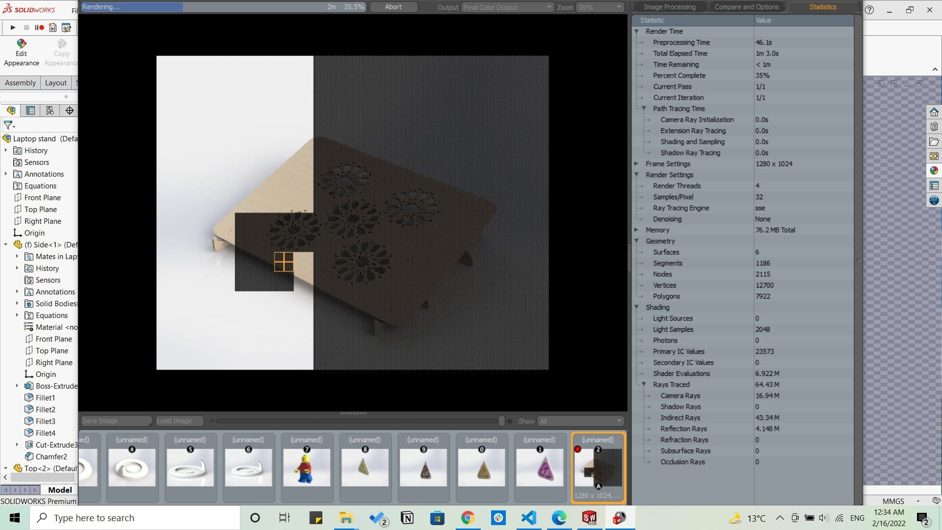
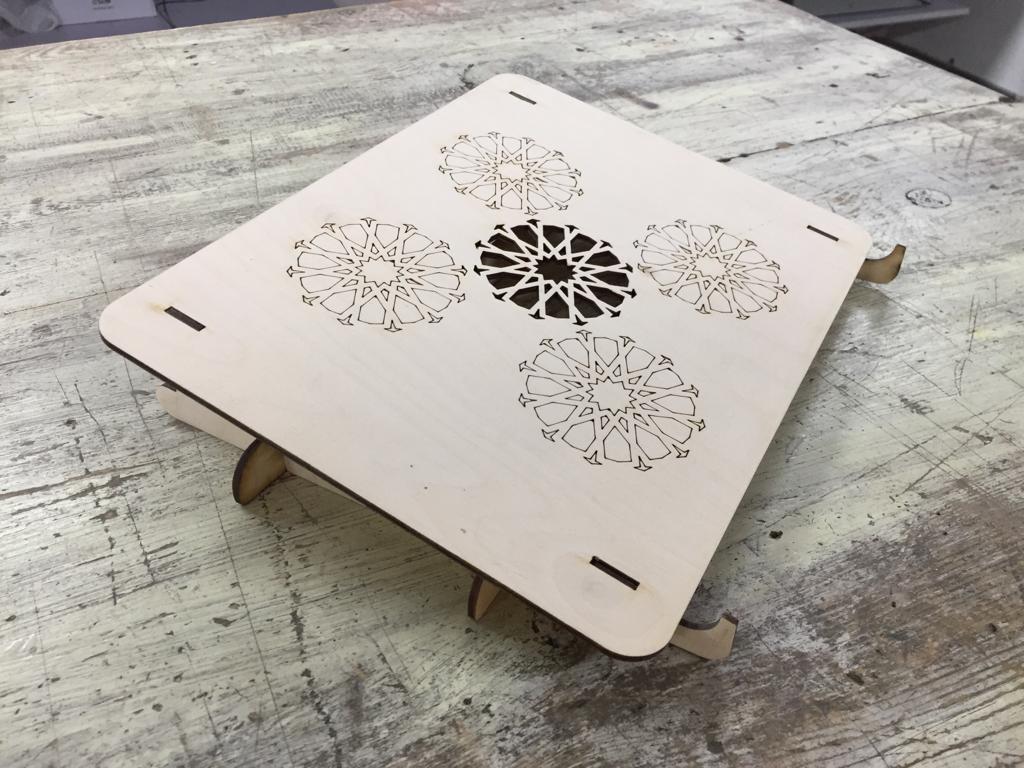
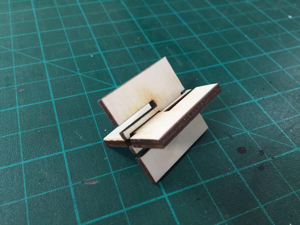
Then I started laser cutting the parts, sanding to remove the burning marks, and assembling it.
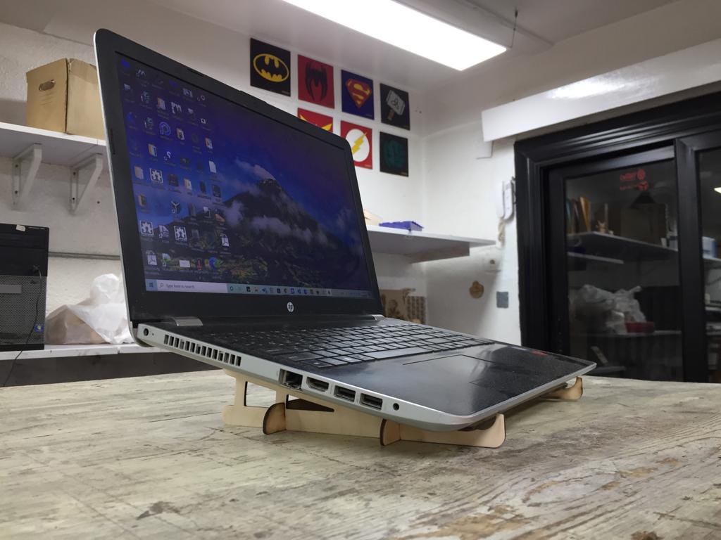
And this was the final shape.
Joints
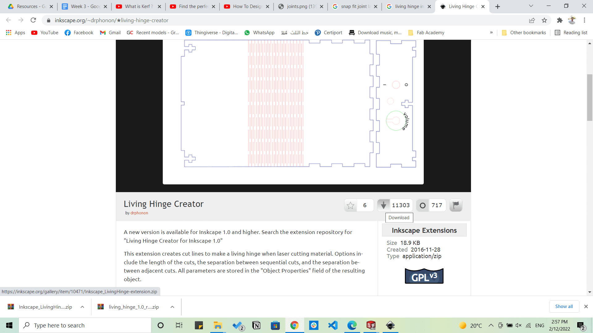
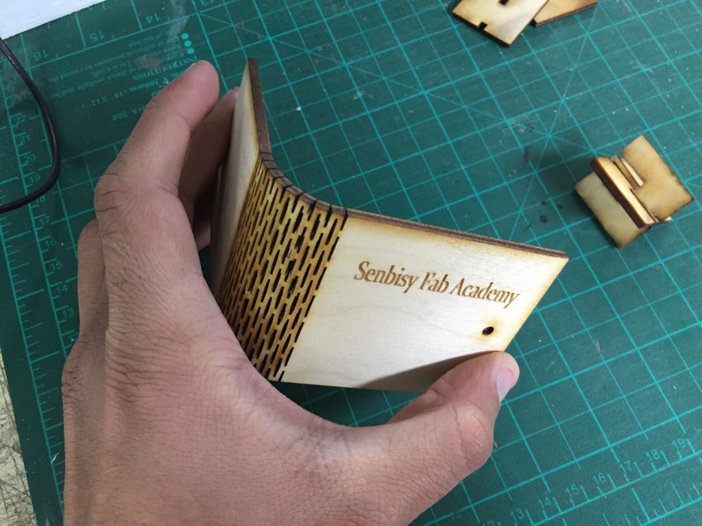
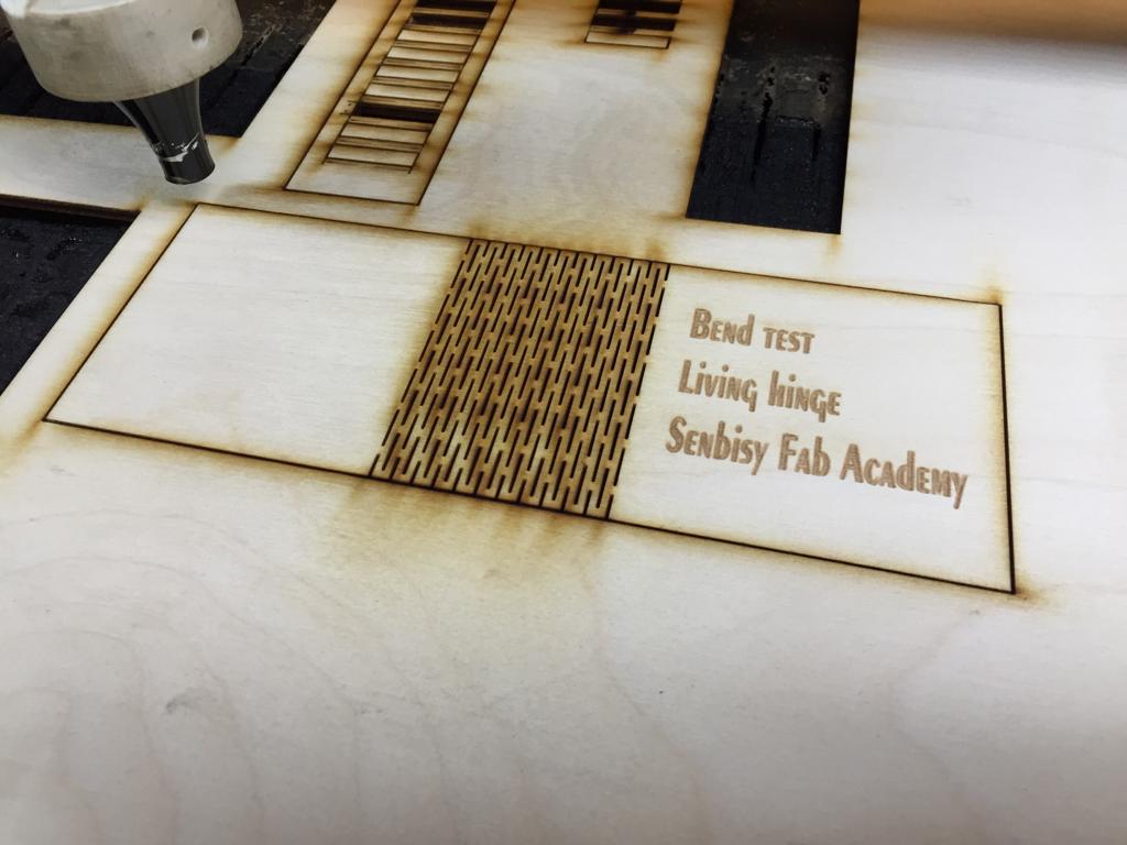
After that I wanted to make some different joints, so I made a living hinge that can bend till90 degrees and a flexure joint.
And creating a living hinge was a bit difficult to do manually, so my collegues Moiz and Amany, , suggested to use an add-in in inkscape that creates a living hinge automatically by adding some parameters, you can find its download link here And actually they came out perfectly :)
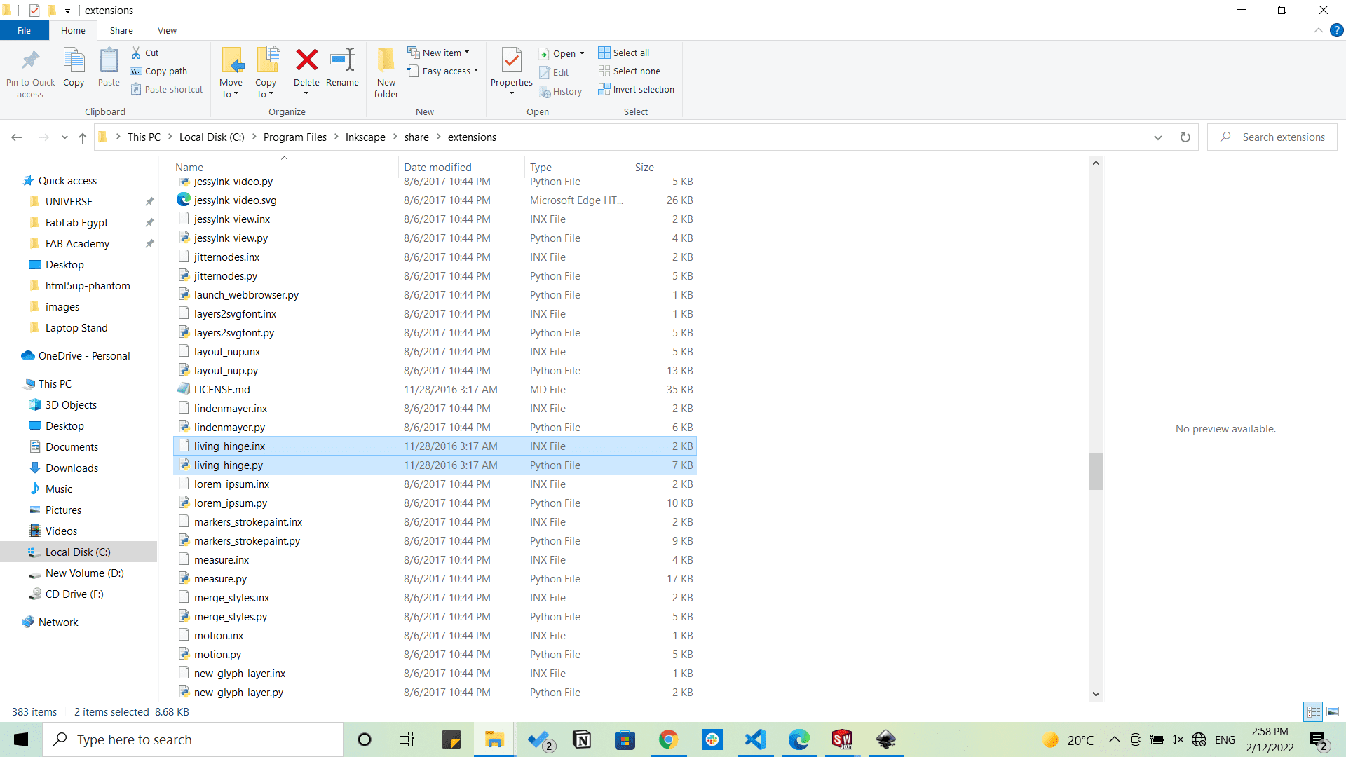
Then copy the files downloaded to C:\Program Files\Inkscape\share\extensions
Assignment
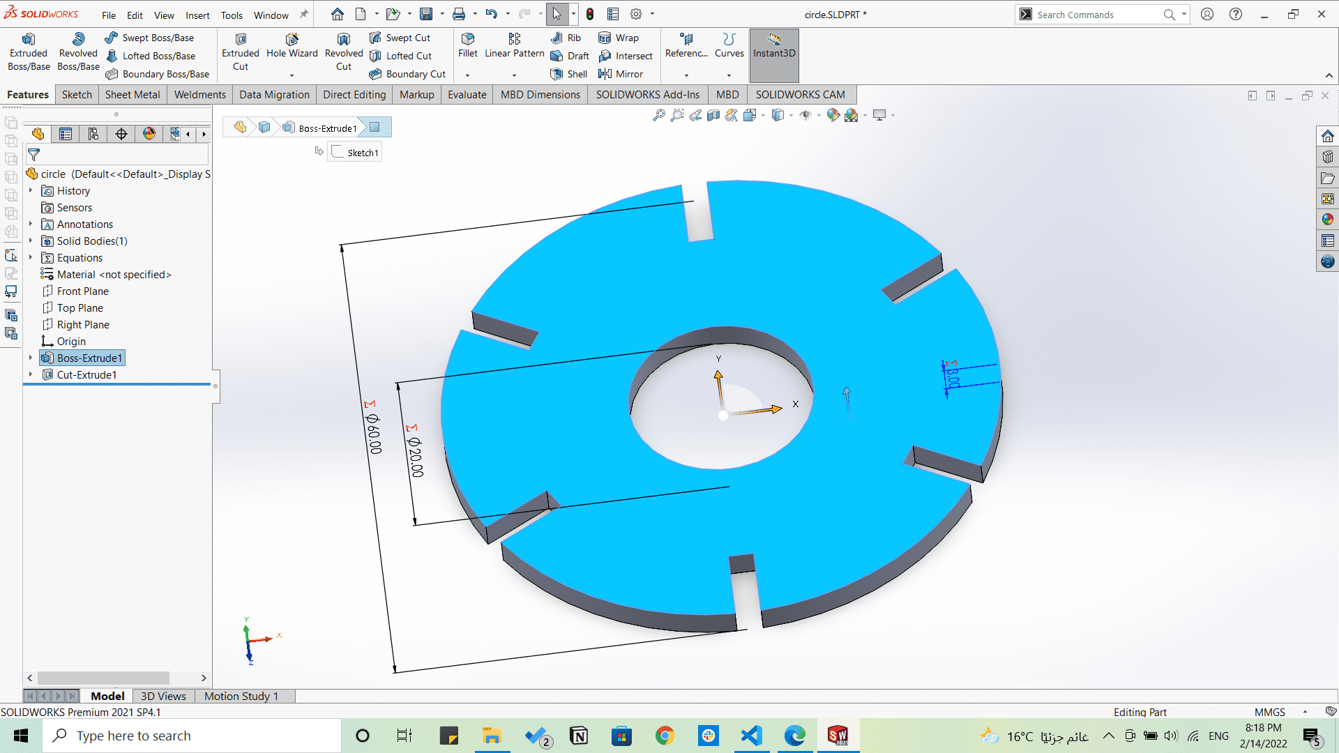
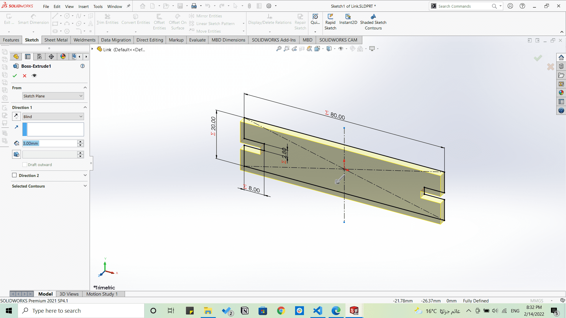
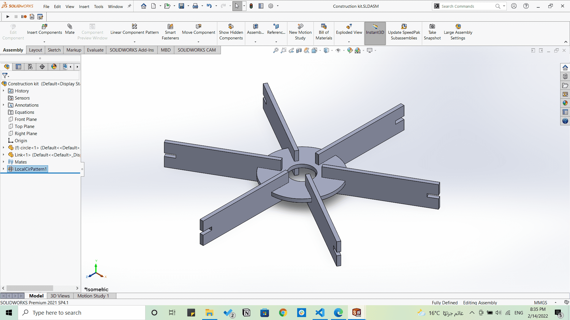
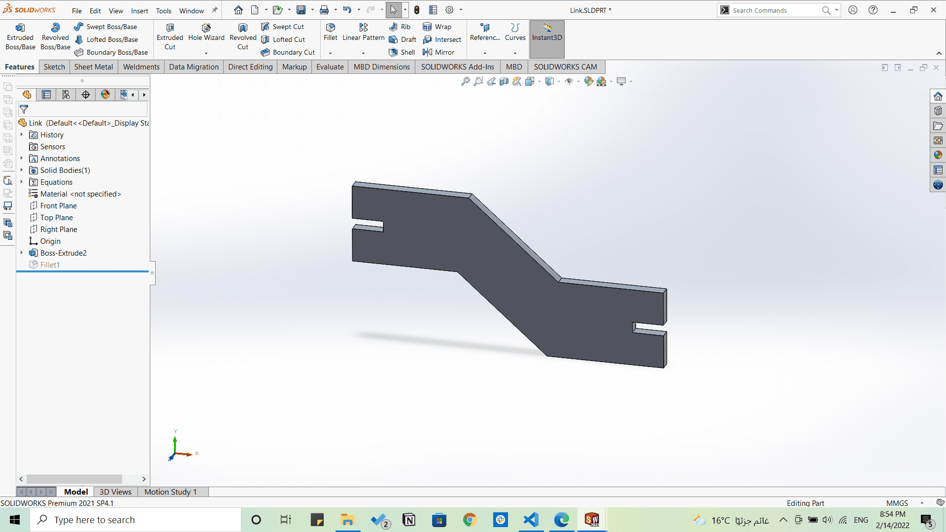
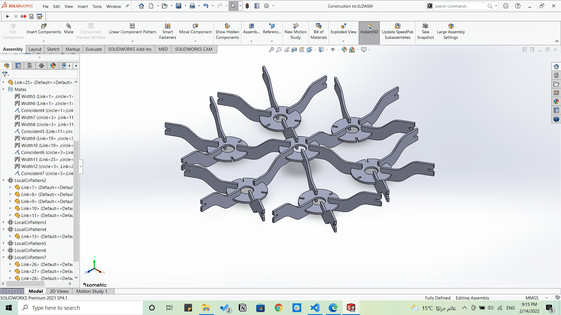
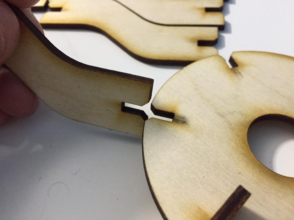
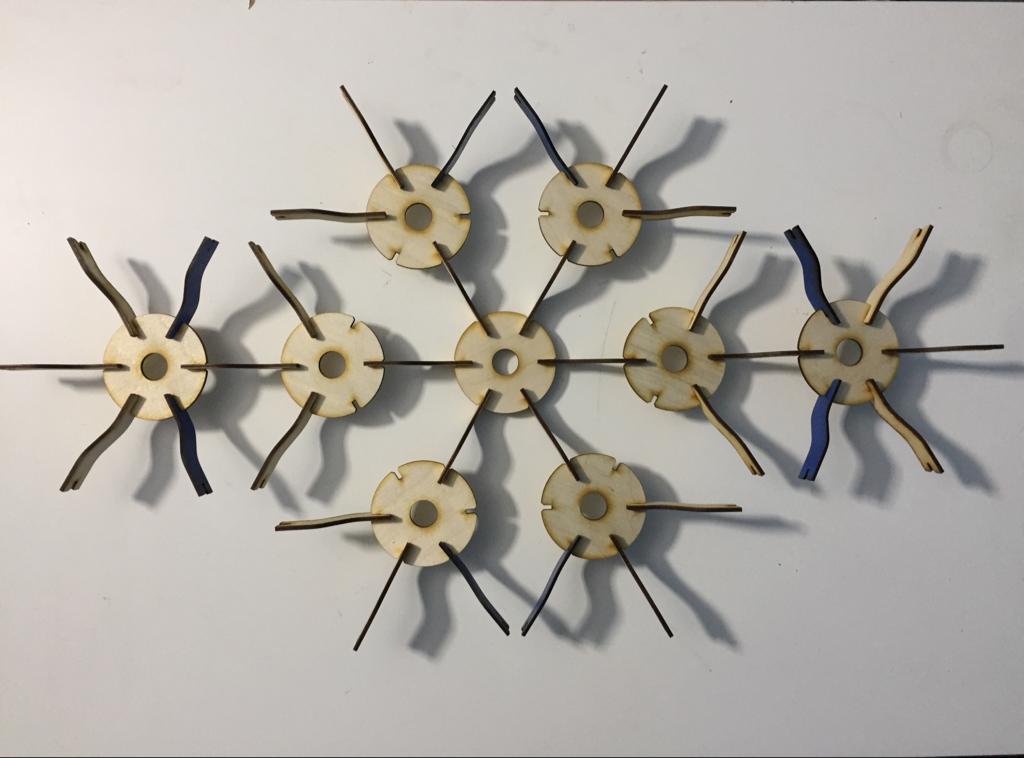
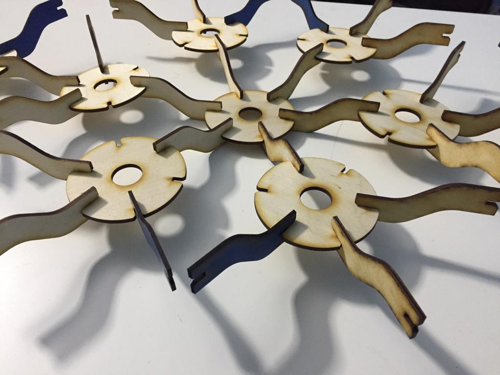
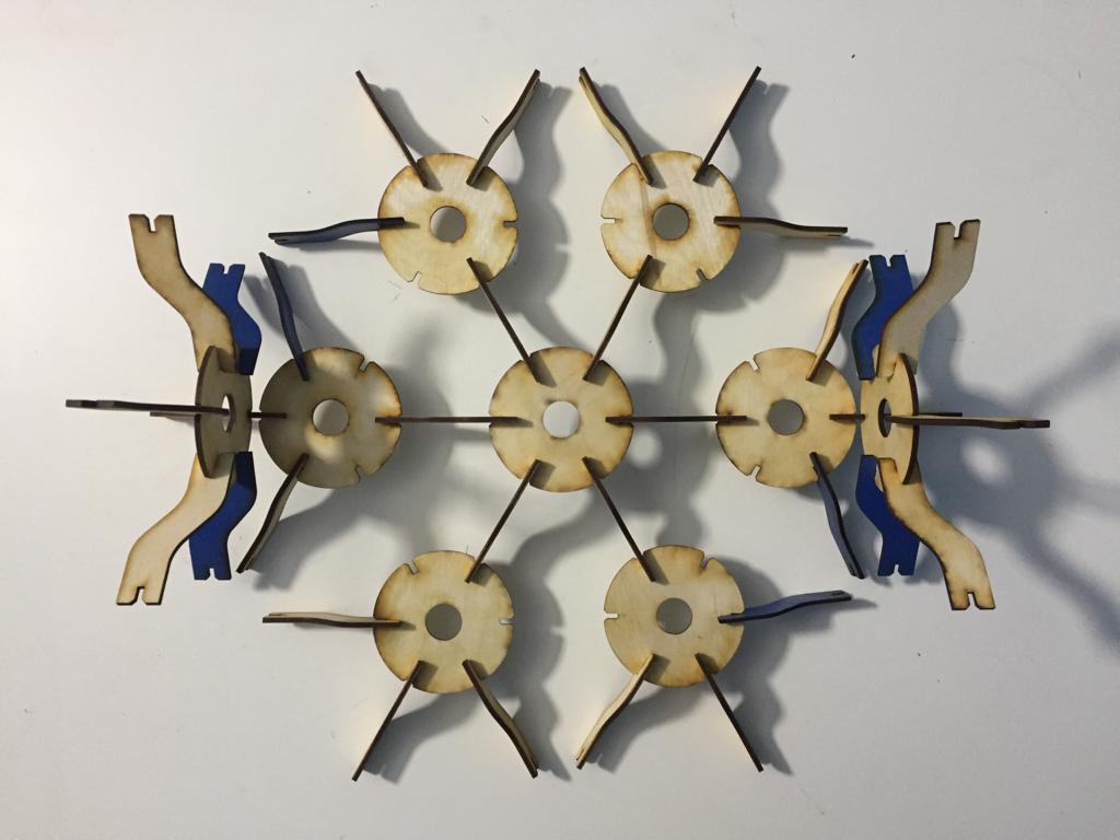
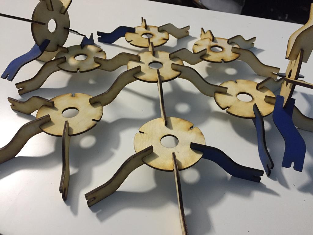
A. Parametric construction kit
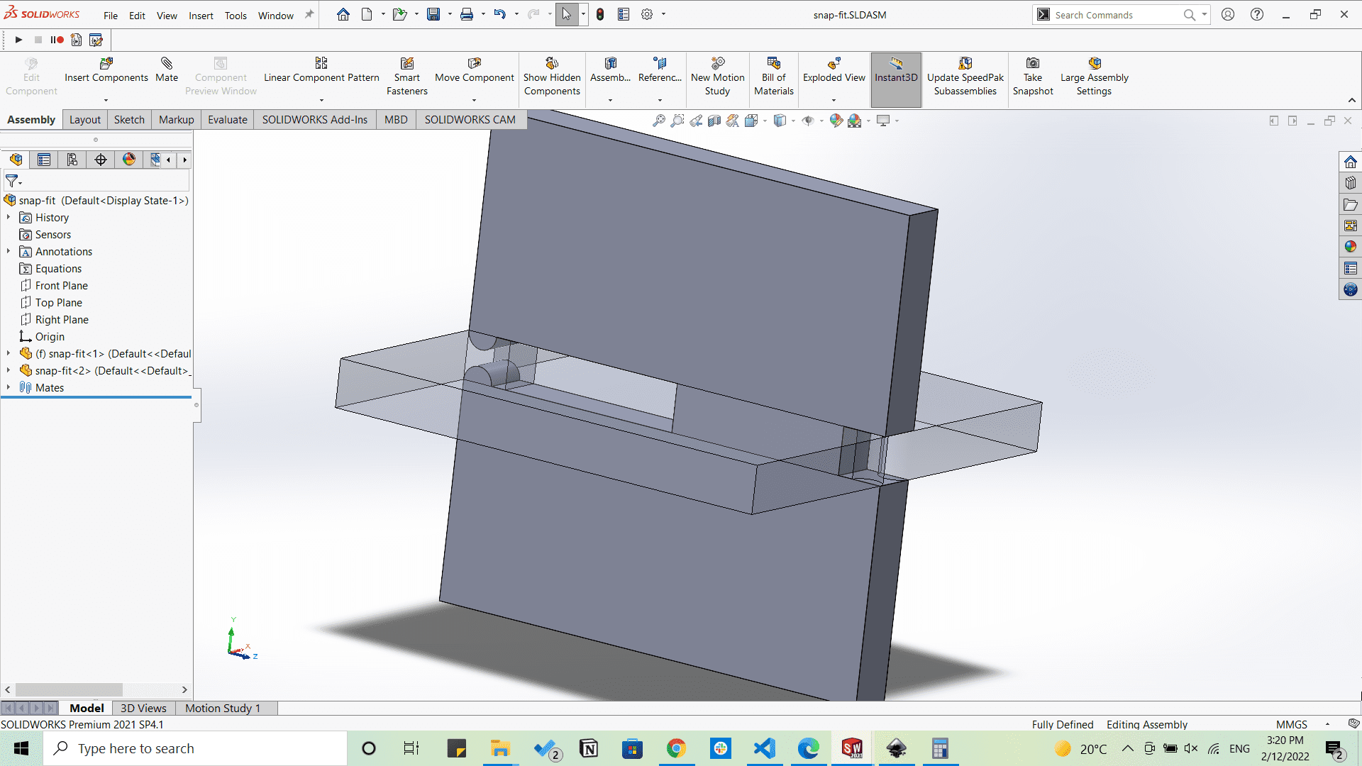
I started by designing by SolidWorks two parametric basic shapes that came in my mind to make something that can be hanged on a wall and also can be assembled in different ways to give different shapes and patterns.
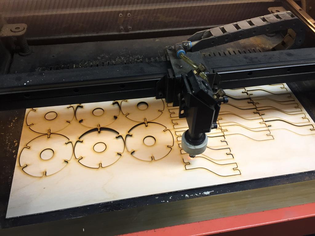
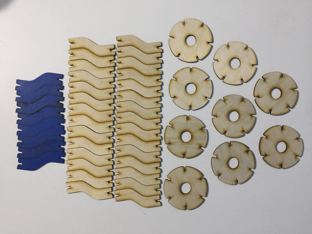
Then I started cutting them.
B. Vinyl Cutting
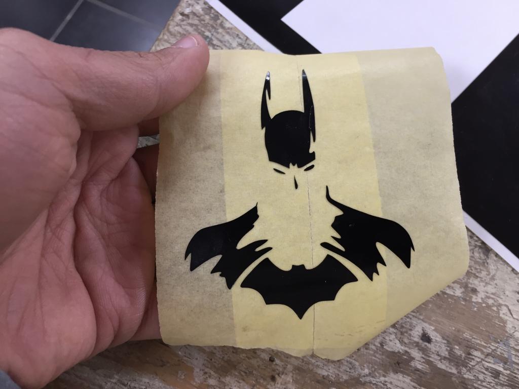
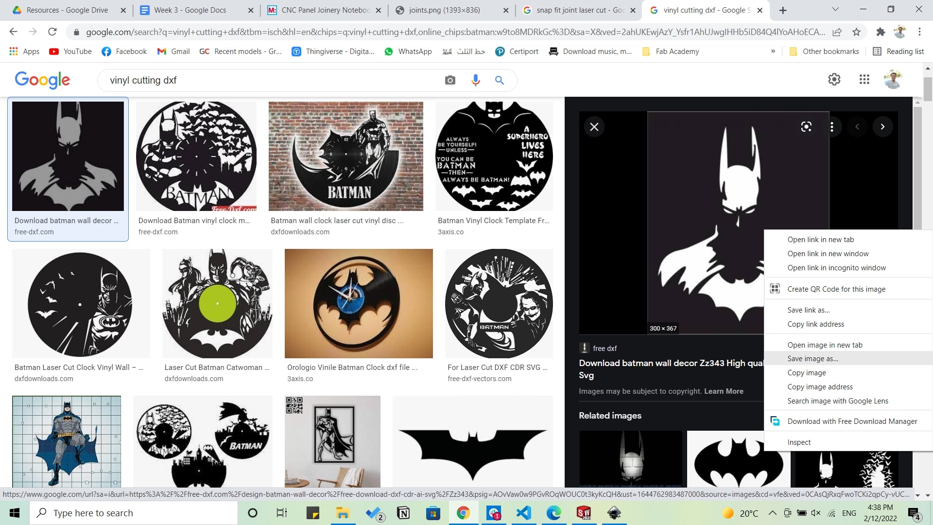
Now its time for vinyl cutting, and as I love watching Batman so much so I decided that I'll be cutting a clipart picture of him. So I started by searching for a suitable picture.
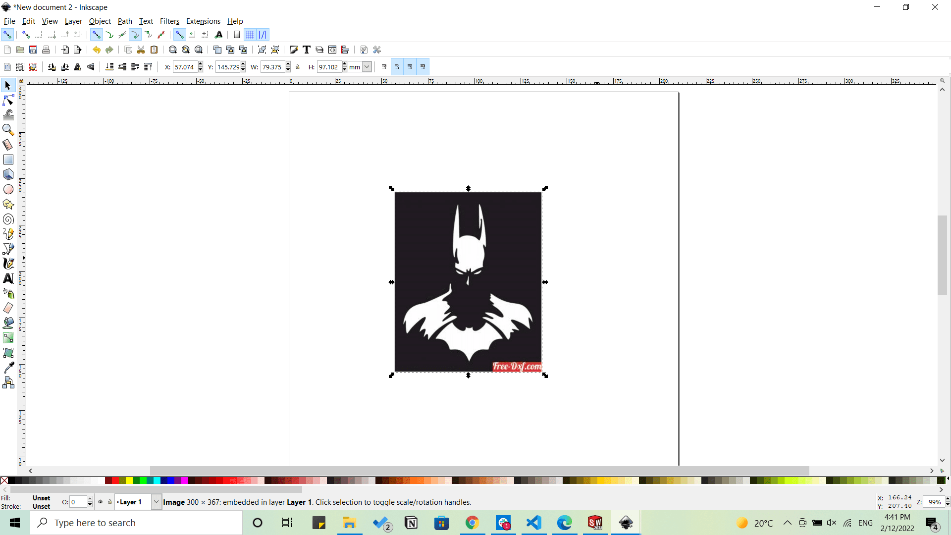
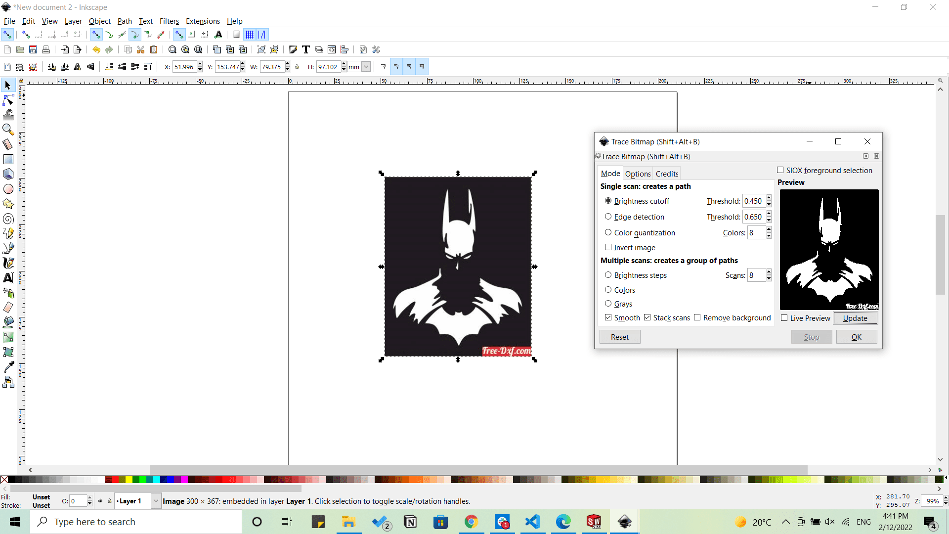
Importing the picture to Inkscape to trace it from Path>Trace bitmap.
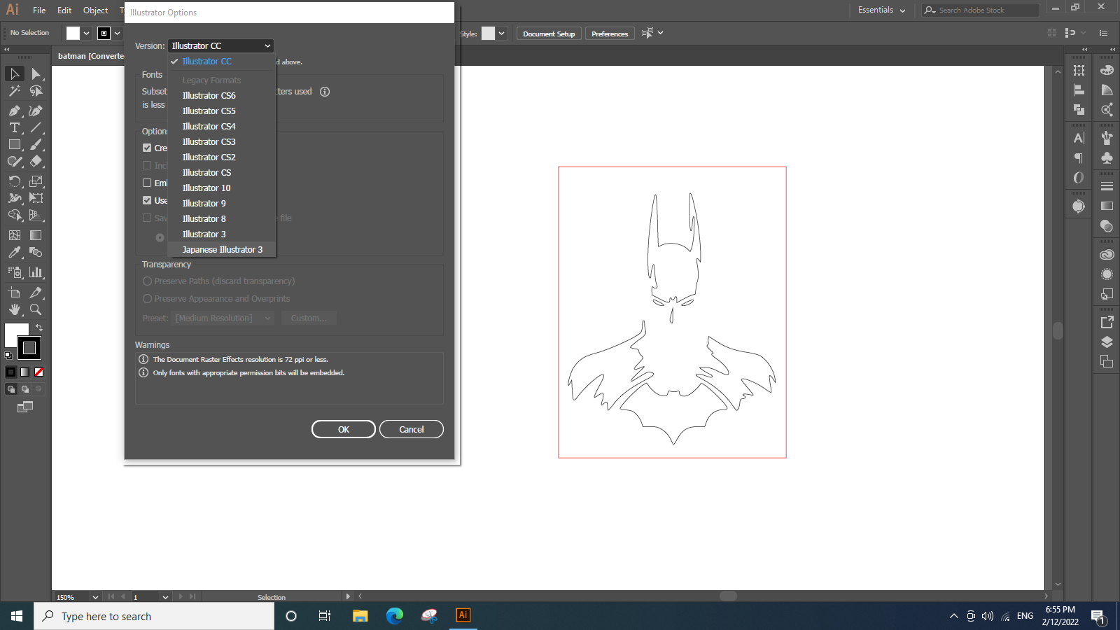
Then exporting the file as .dxf. and importing it on the machine's computer into Adobe Illustrator.
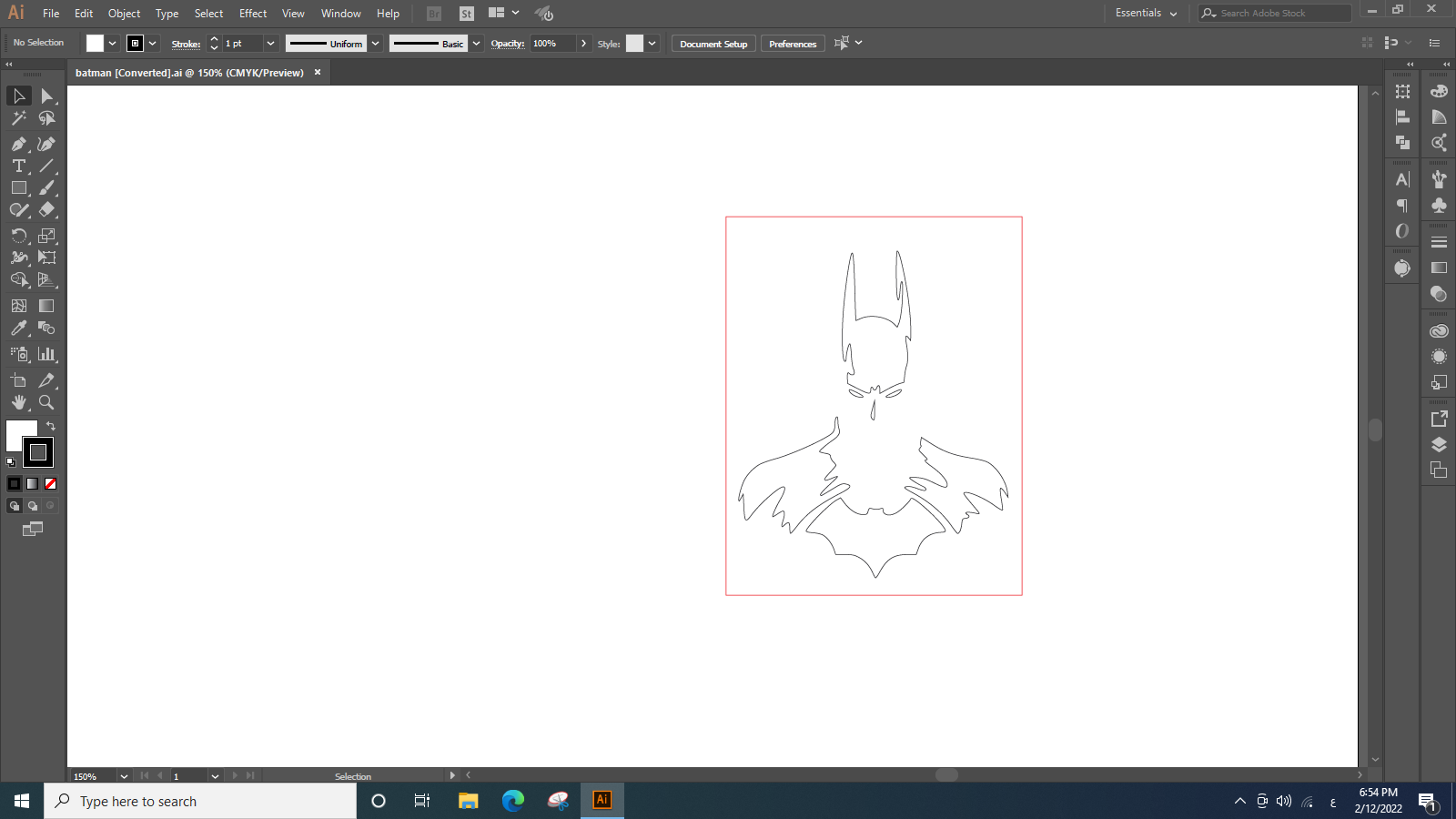
And we did this in order to export the file in an AI "Japanese Illustrator 3" version that can be read by the machine's operating software CutStudio.
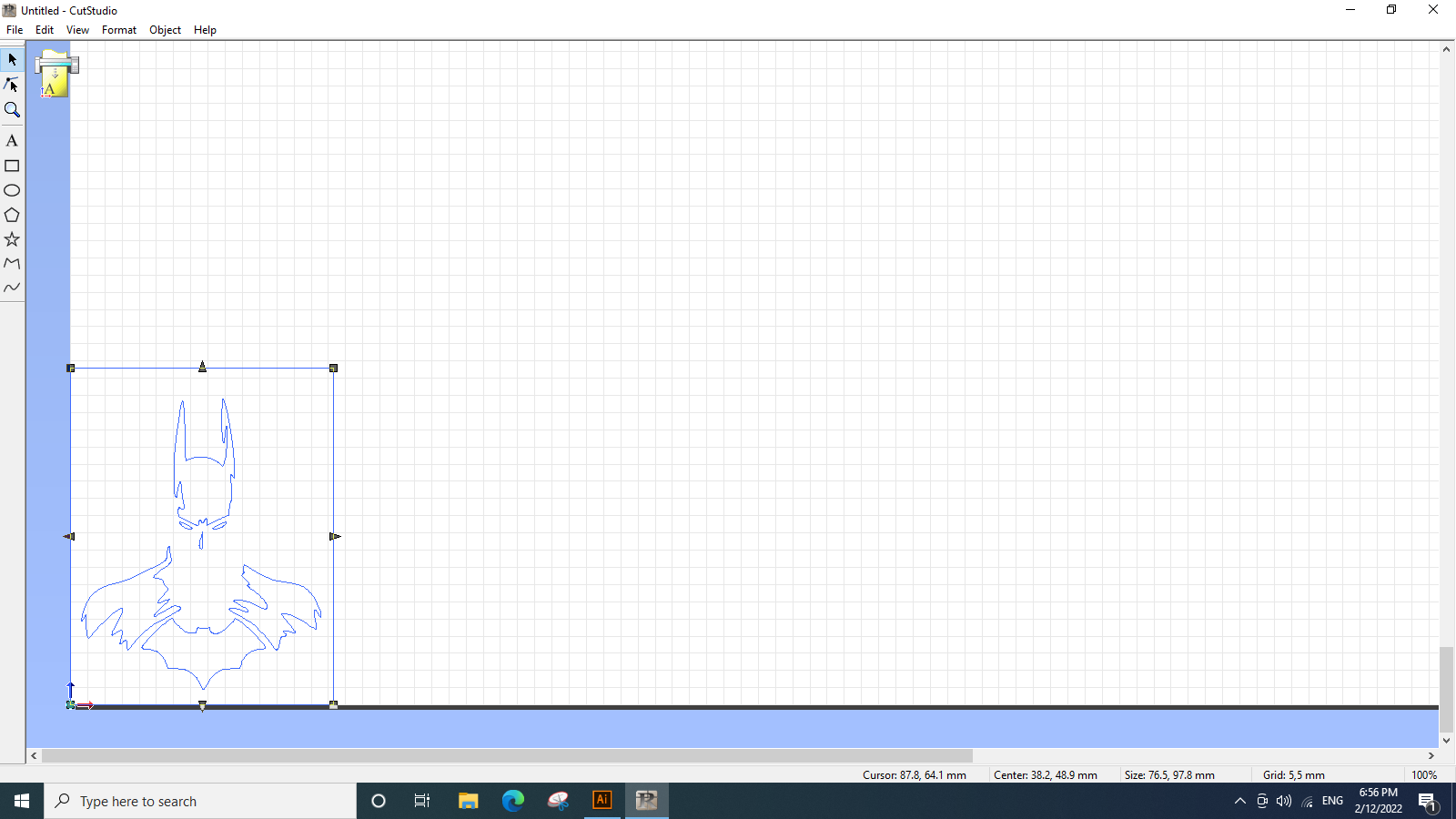
Then we will open the file on Cut Studio that operates the Rolland vinyl cutter.
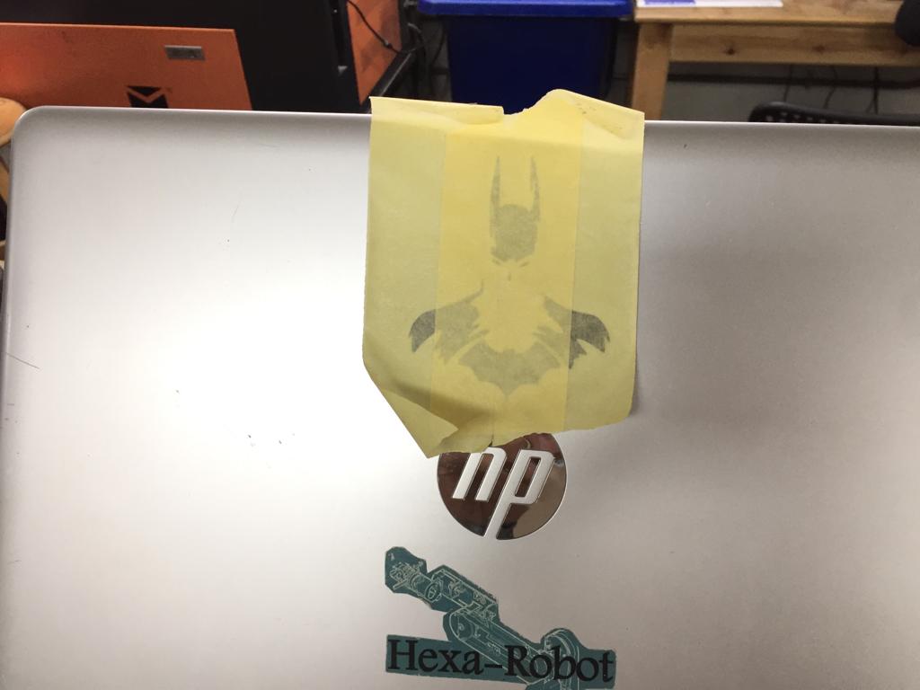
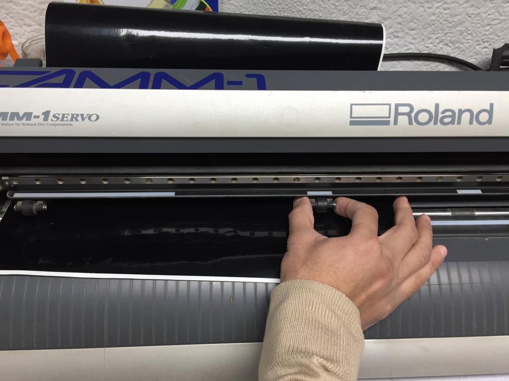
Then we will just start cutting after installing the vinyl shet into the machine, and setting the rollers> into their position according to the Sheet size.
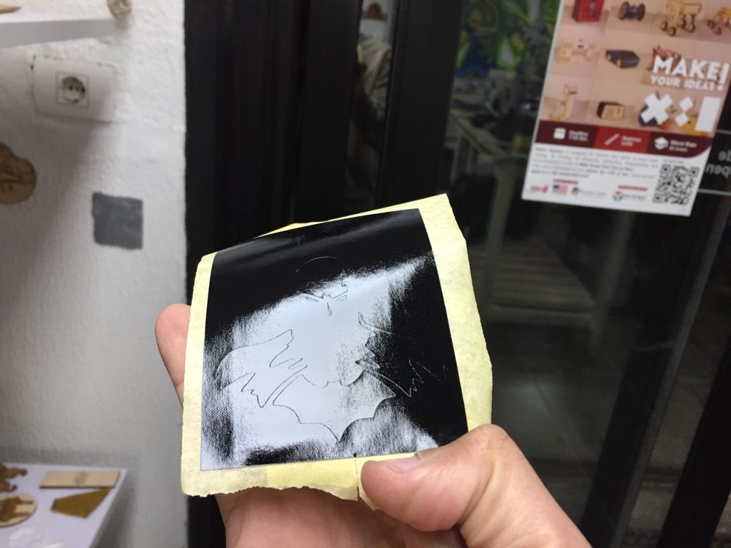
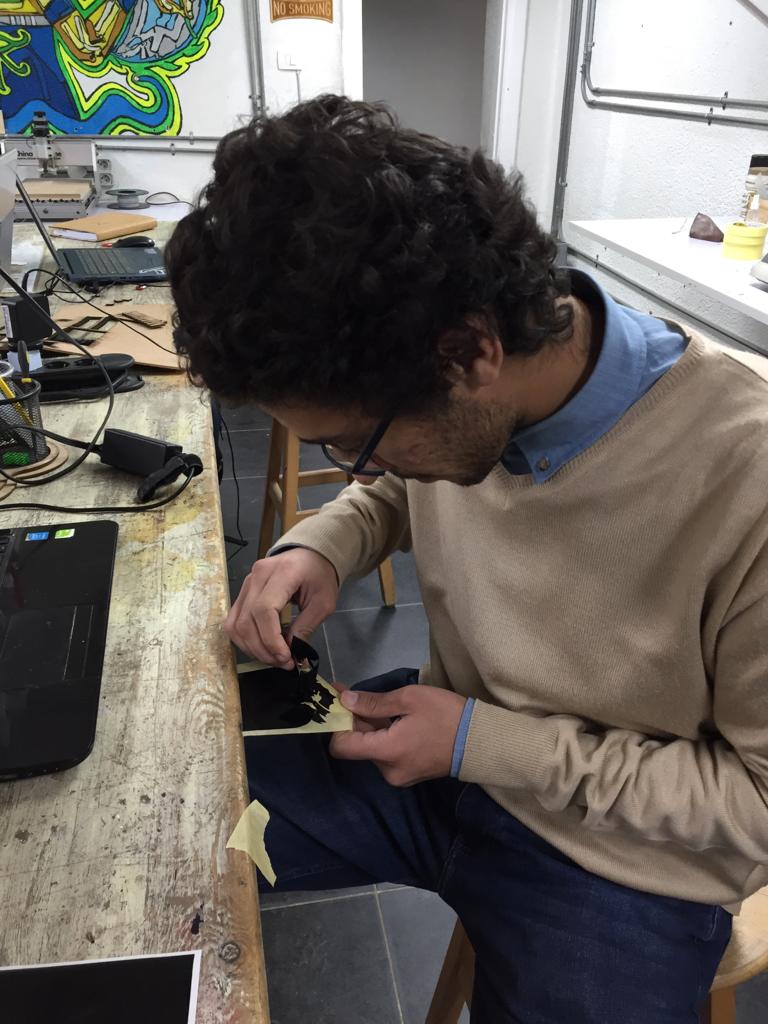
And this was the output