
Week 14
Interface & Application Programming
-
Group Assignment
- Compare as many tool options as possible Individual Assignment
- Write an application that interfaces a user with an input &/or output device that you made
Group Assignment
In this assignment I used the board that I made in the student's bootcamp and used Processing to operate it. The board was simply having an attiny44 microcontroller and 6 LEDs.
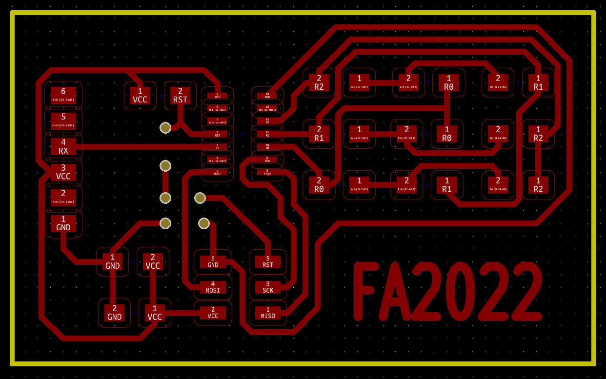
Board Schematic
- Attiny44 (x1)
- SMD LED (x6)
- 4.99k ohm resistor (x3)
- 1k ohm resistor (x1)
- 0.1uF capacitor (x1)
- 1uF capacitor (x1)
- Straight pin headers (x6)
- Right angle pin headers (x6)
Components
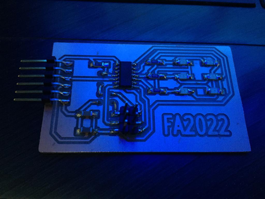
Then I soldered the board accordingly
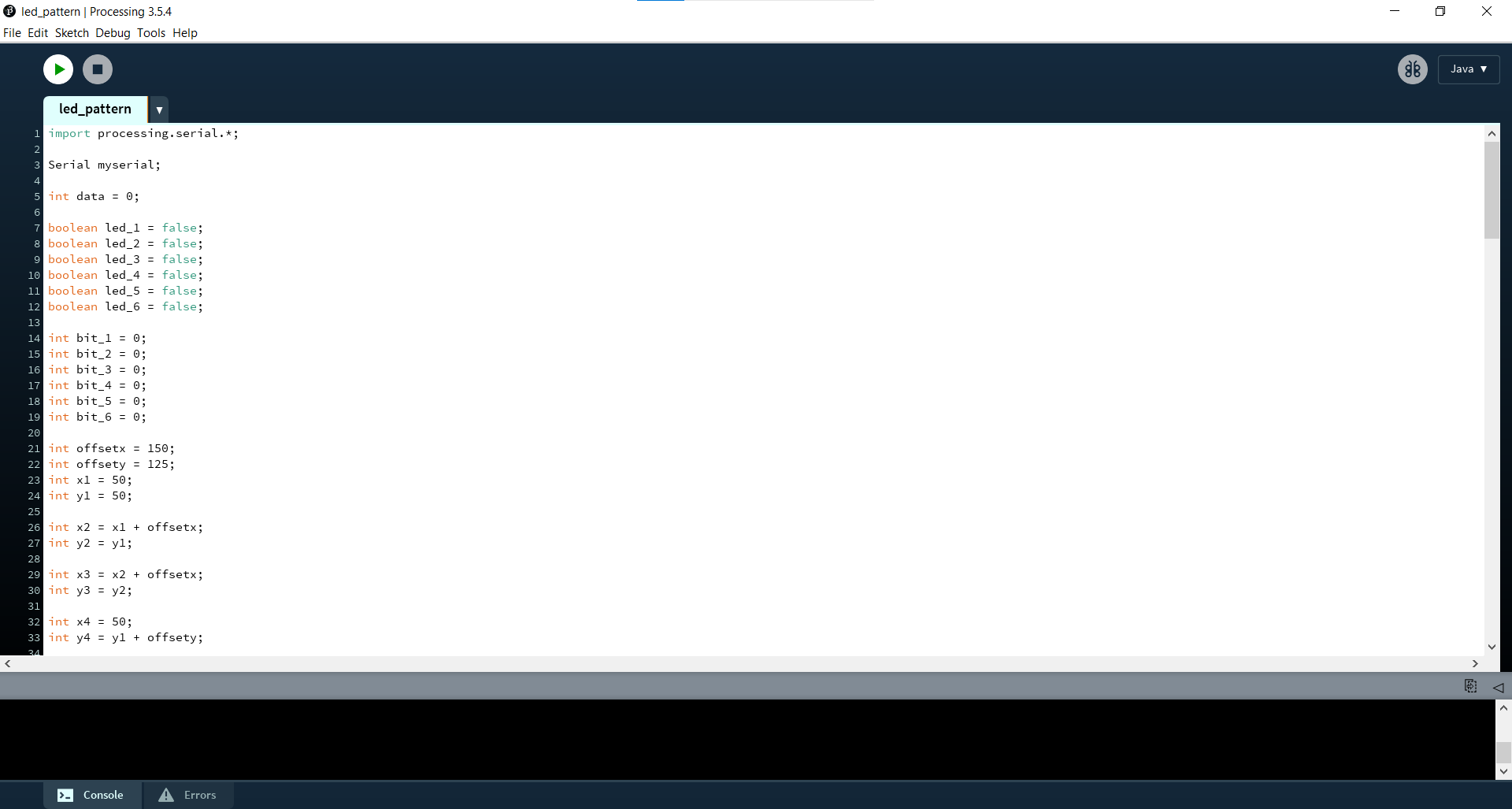
After that I downloaded Processing to make a small program that turns the LEDs ON and OFF.
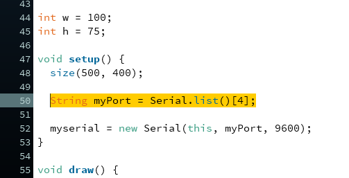
After that was writing the code on processing as shown. Which turns On any LED pressed on the screen.
Then after writing the code on processing I pressed on Run and waited for a while for the GUI (Graphical User Interface) to run.
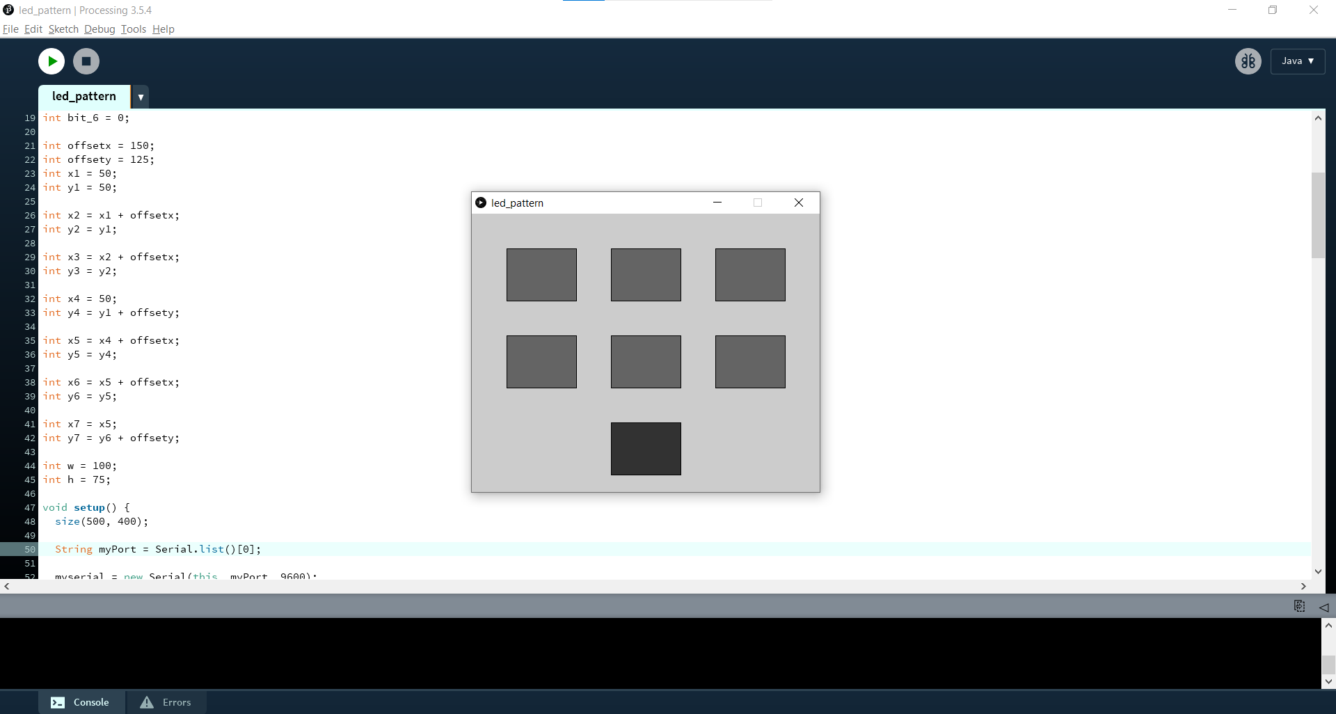
If it doesn’t work you can only change the port number as shown, as it worked with me on 4 instaed of 0.
Individual Assignment
In this assignment I managed to make an application by Matlab on an Arduino UNO board, and I wanted to run the same application on my own Atmega328p but that didn't work so far.

Matlab Software
So I started by making the application through GUIDE, so all I have to do is so simple, I just design the application shape it it will generate automatically the code for each button, slider, etc... as required but without the function needed which I will have to add.
So by typing guide in the Command Window, a new GUI can be created simply.
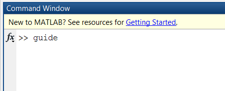
Typing guide in the command window
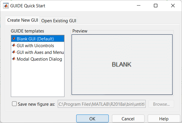
Creating new GUI
Then all we need to do is start adding our controllers, such as Push buttons, Sliders, and so on...
Simply, I started with 2 push buttons for testing the whole process, so after adding them, I just needed to type the code that will turn the LED ON and OFF.
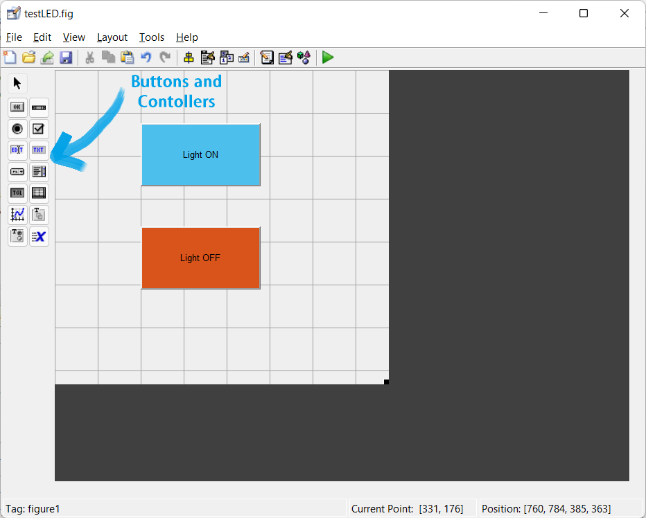
Creating new GUI
The code simply had 2 push buttons, so I typed the syntax that turns the LED ON and OFF as shown and that worked perfectly.
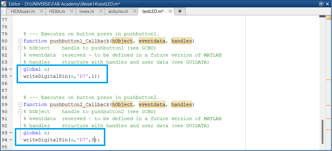
Push buttons functions
Matlab/Arduino LED ON/OFF
After that worked I wanted to add more control buttons and try controlling a DC motor. So I designed this GUI as shown that controls the rotation speed of the motor and it's direction, and shows the speed of the motor by a photointerrupter sensor I made earlier in the input devices week, and also the same LED ON/OFF control.
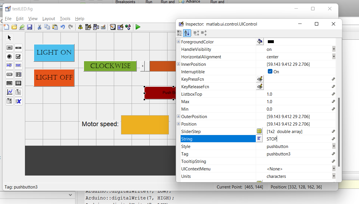
Designing a new GUI for DC motor control
And this was the final shape of the application.
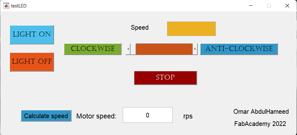
DC motor contol application
DC motor control Matlab/Arduino Application
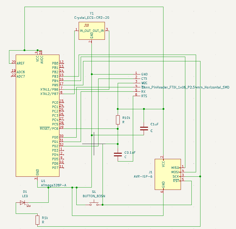
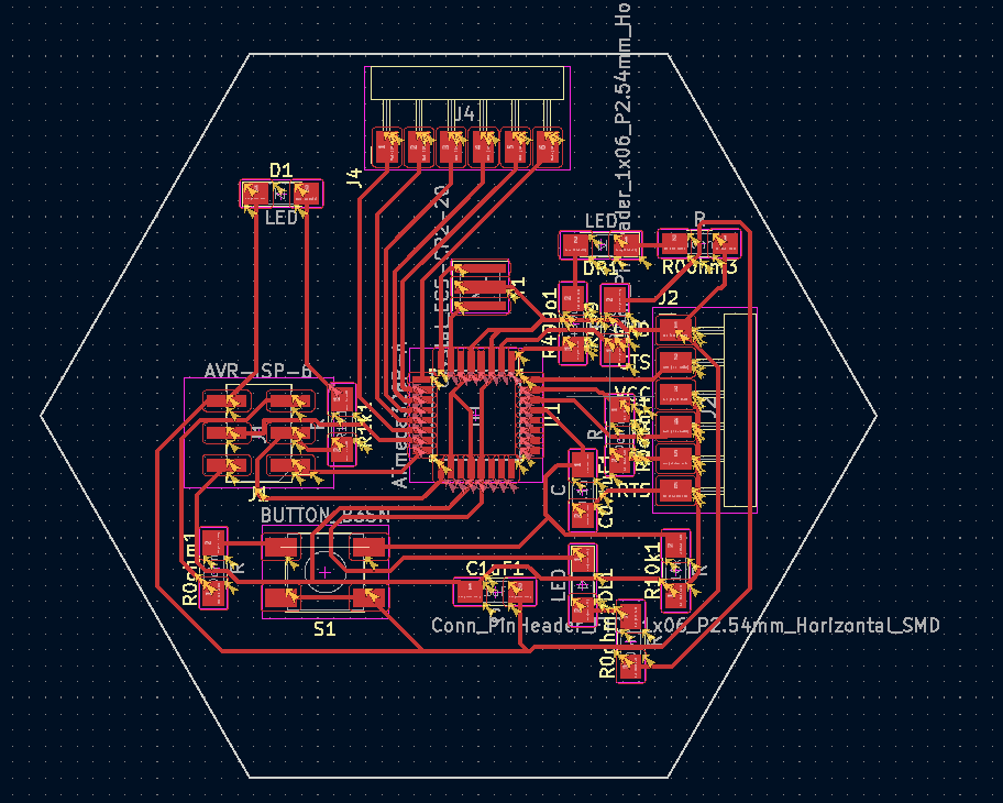
Then I wanted to make that on my own Atmega328P board. So I started designing it on KiCAD.
And I milled that on our Modella MDX-20 machine.
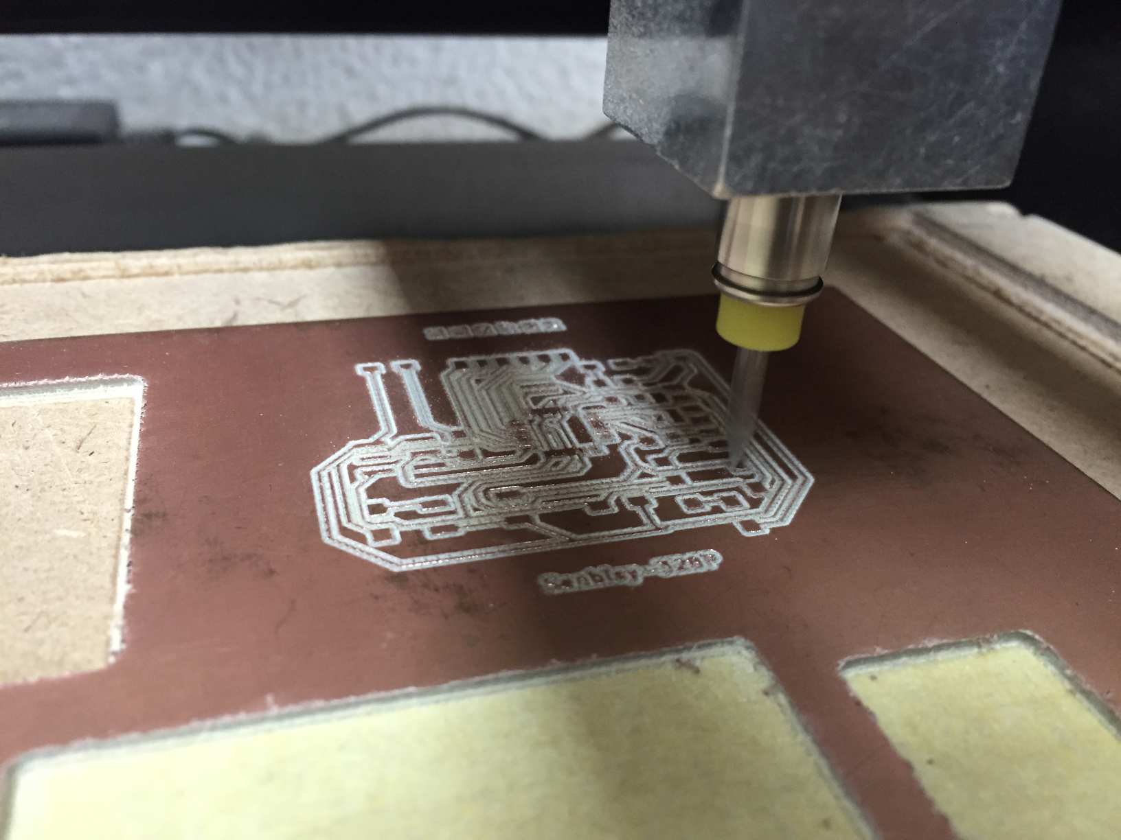
Senbisy 328P board being milled
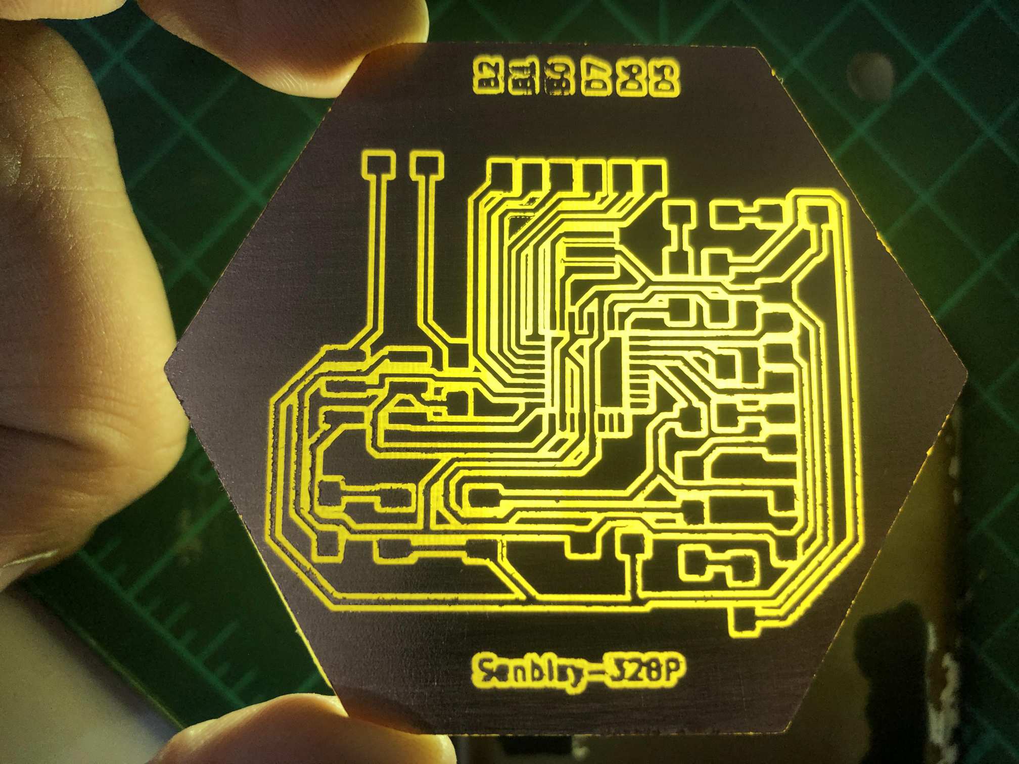
Senbisy 328P board milled
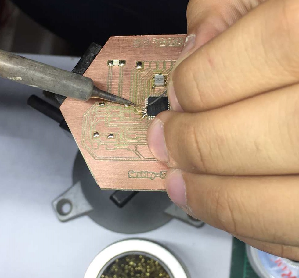
Soldering Senbisy 328P board
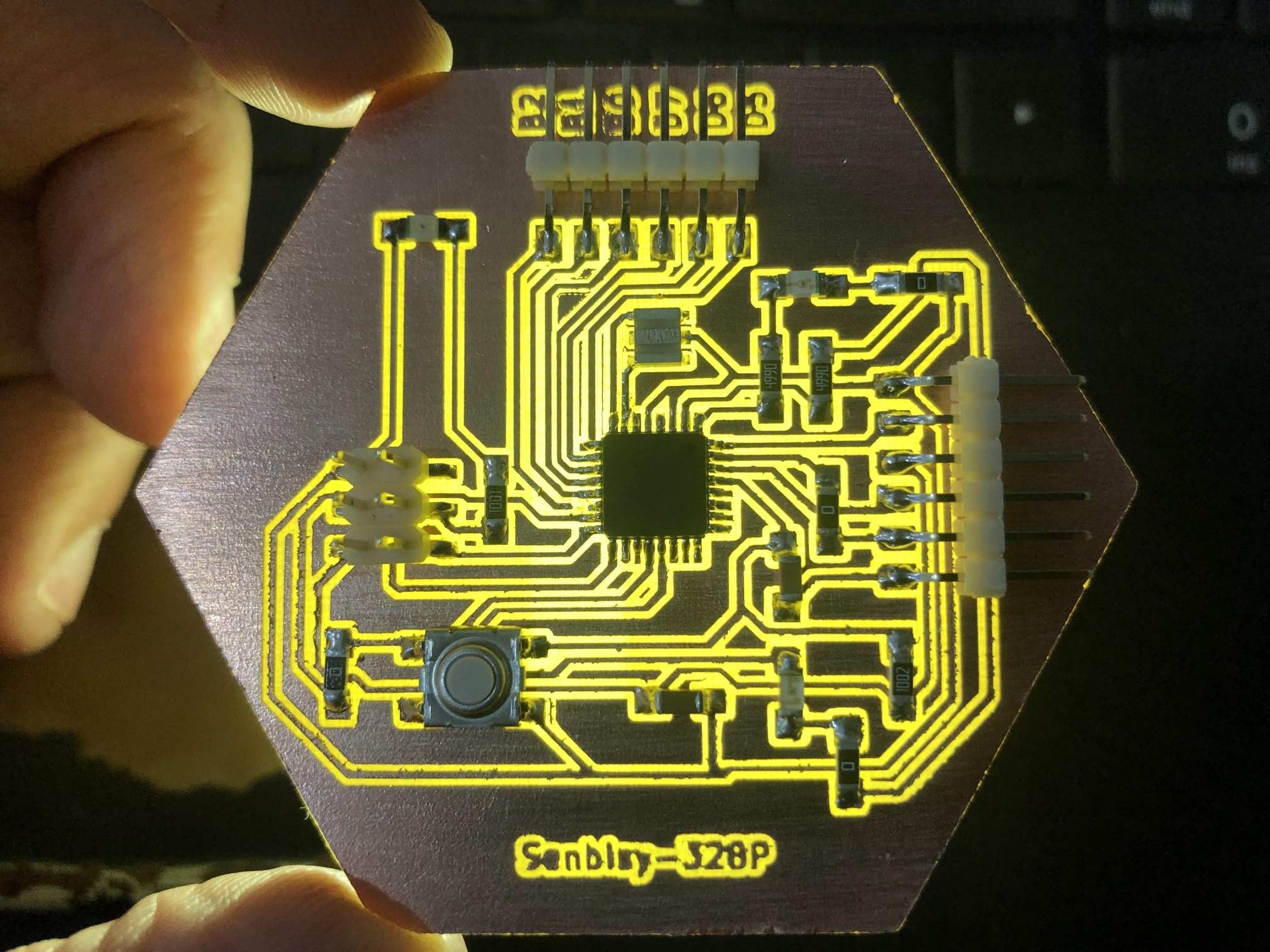
Senbisy 328P board soldered
So in order to use it I have to burn the Bootloader that makes it an Arduino UNO board. So I followed this documentation that explains how to install it by MiniCore. MiniCore
And I added the MiniCore library as mentioned in order to burn the bootloader.
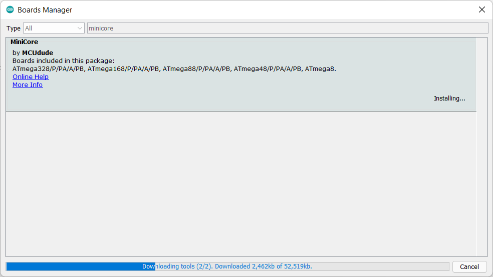
MiniCore library
Then I connected the FABISP programmer to burn the bootloader.
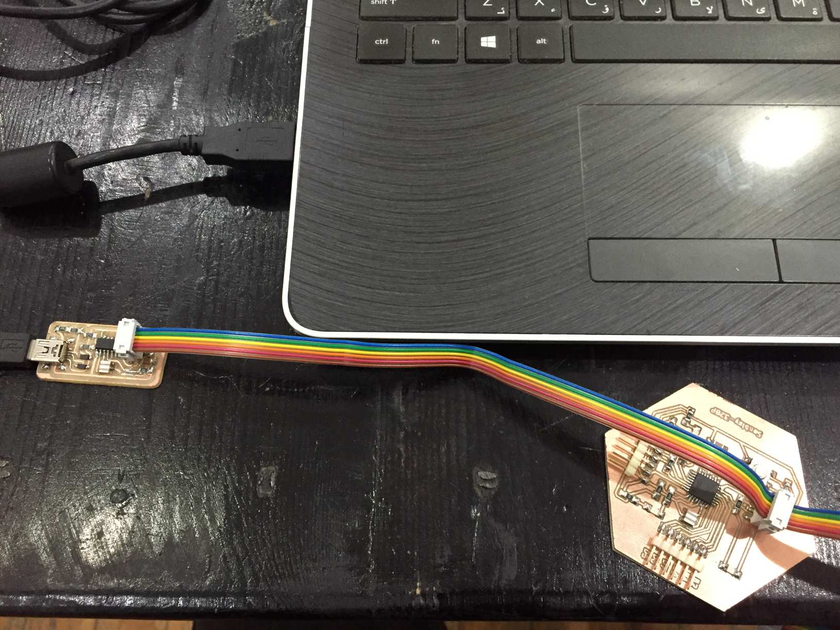
FABISP as a programmer
Then I read in the previous documentation that if everything went correct the LED connected to pin13 should blink every second, and that what actually happened.
Bootloader uploaded successfully
Downloads