
Week 12
Input Devices
-
Group Assignment
- Probe an input device's analog levels and digital signals Individual Assignment
- Measure something: add a sensor to a microcontroller board that you have designed and read it
Group Assignment
In this week's group assignment we made a board that has a Phototransistor that senses the light and changes the voltage accordingly.
Phototransistor diagram
When no current passes from the LED, obviously the phototransistor is switched Off, thus the whole amount of current passes from the A0 branch. In that case I read from A0 a 1023 value which is equal to 5V for a 10bit ADC (Arduino).
So according to that we turned the light ON and OFF to see the output voltage.
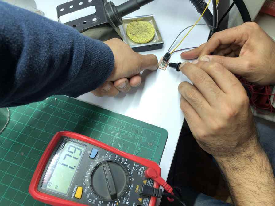
Turning light ON
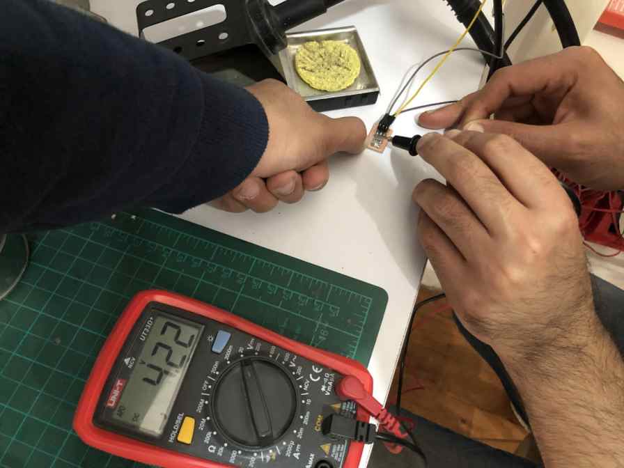
Turning light OFF
As we can see, when we turned the light ON it gave us 1.79v, and when turned OFF it was 4.22v.
And here was the output by changing the light intensity on the sensor.
Light sensor changing intensity
Then we needed to probe that on the oscilloscope. Displaying them once as digital reading which must show the readings once as +5V and when the light is near should be 0V, and once as an analog signal that displays a variation from 0V upto +5V.
Analog display while changing the intensity
Digital display while changing the intensity
The next sensor we used as a group was the temperature sensor.
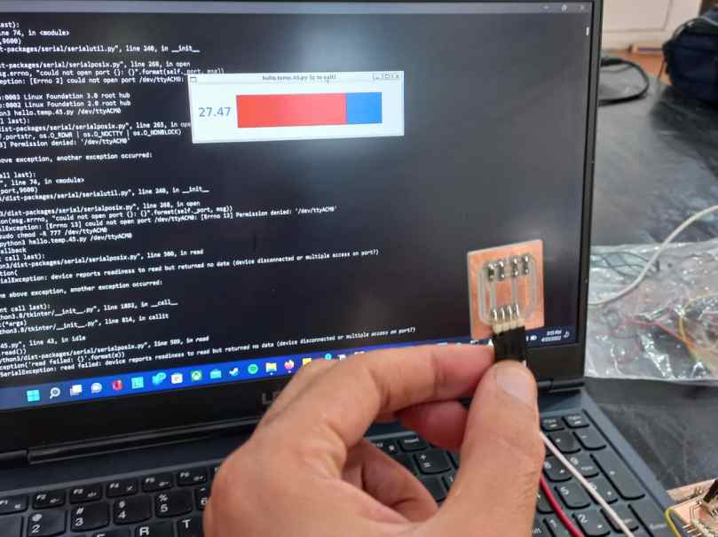
Temperature sensor board
And with a simple code on Python we got the response as following.
Temperature sensor
Individual Assignment
For the individual assignment I decided to try sensing with step response, so I followed this tutorial that was very helpful. Step response
So I started by getting a piece of copper sheet, and cut it in half to get 2 pieces.
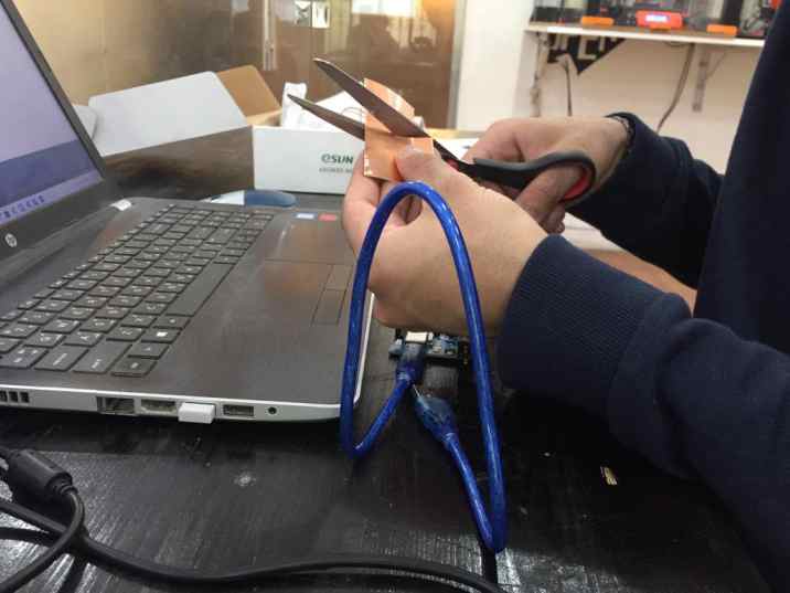
Cutting a copper sheet
Then I soldered a jumper into each one of them
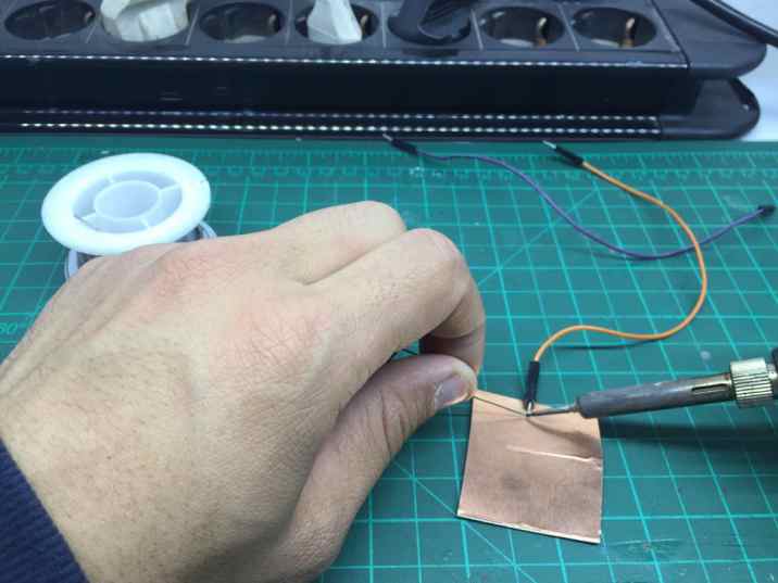
Soldering a jumper into the copper sheet
Then I got the code for the link mentioned above and it should print the output on the serial monitor as shown.
You can find his documentation here Roberthart
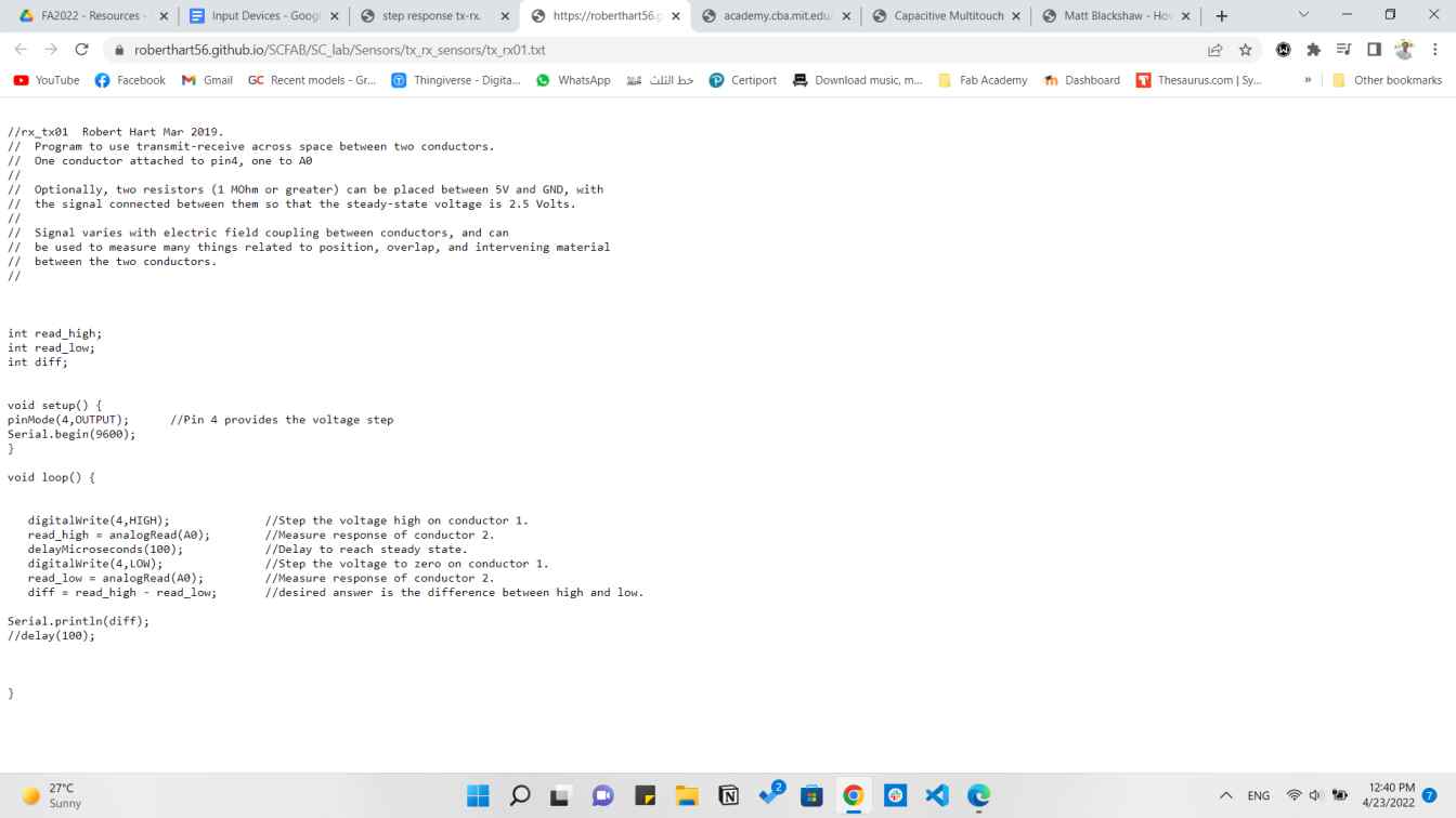
Step response code
Sensing with step response
So what's happening here is that the copper sheets senses the distance between each other and if something is pressed on it. and thoses readings are shown on the serial monitor.
Secondly, I wanted to use a photointerrupter sensor, So I found this circuit that explains how it should be connected.
So the main part in the circuit is the Phototransistor for sure and it needs the LM393 which is a dual comparator chip which is designed to permit a common mode range to ground level with single supply operation
I found this connection here at electroschematics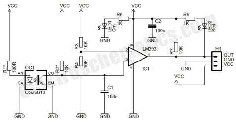
Photo interrupter circuit diagram
The only issue was I didn't find the symbol and footprint for the sensor which was named SFH 9540, so I had to download it from SnapEDA
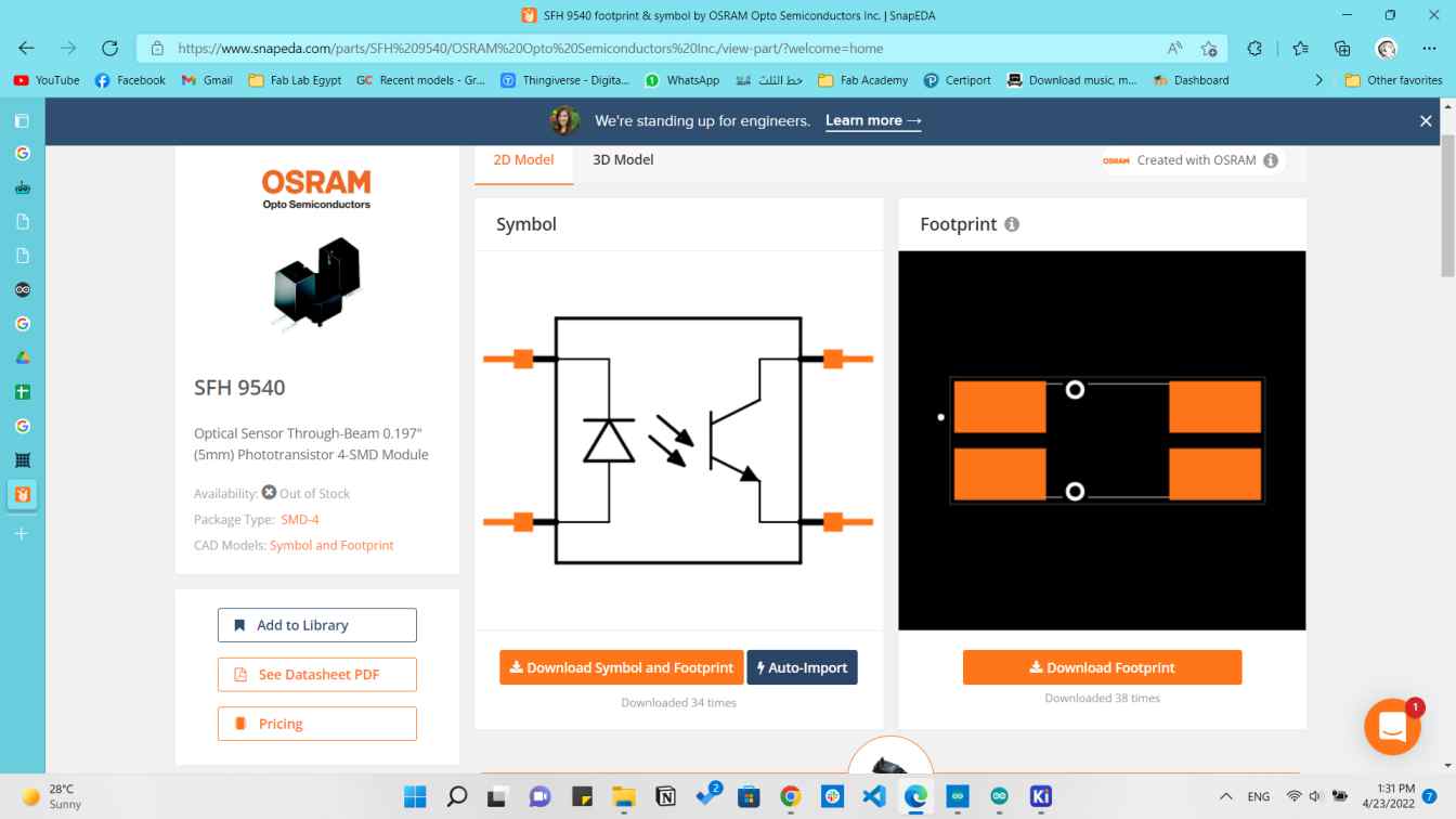
Photointerrupter symbol & footprint
Then I started designing that on KiCAD software.
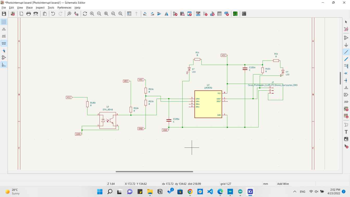
Photo interrupter schematic
And then the PCB design accordingly.
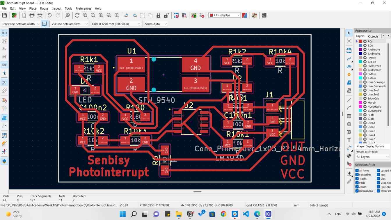
Photo interrupter PCB
Then I started fabricating the board on the Modella machine.
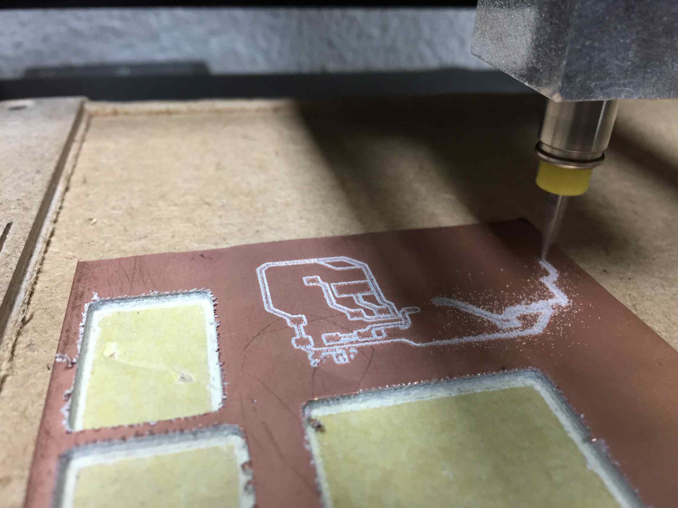
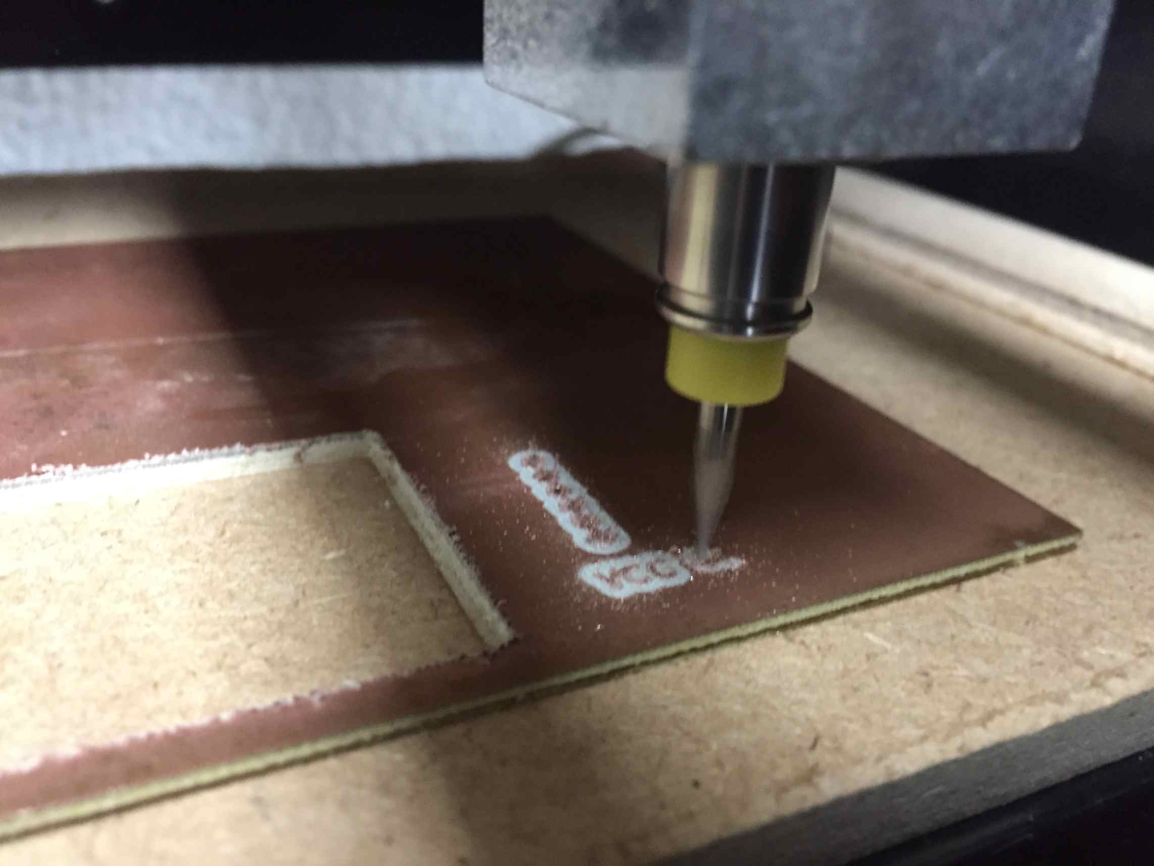
And this was the output of the machine.
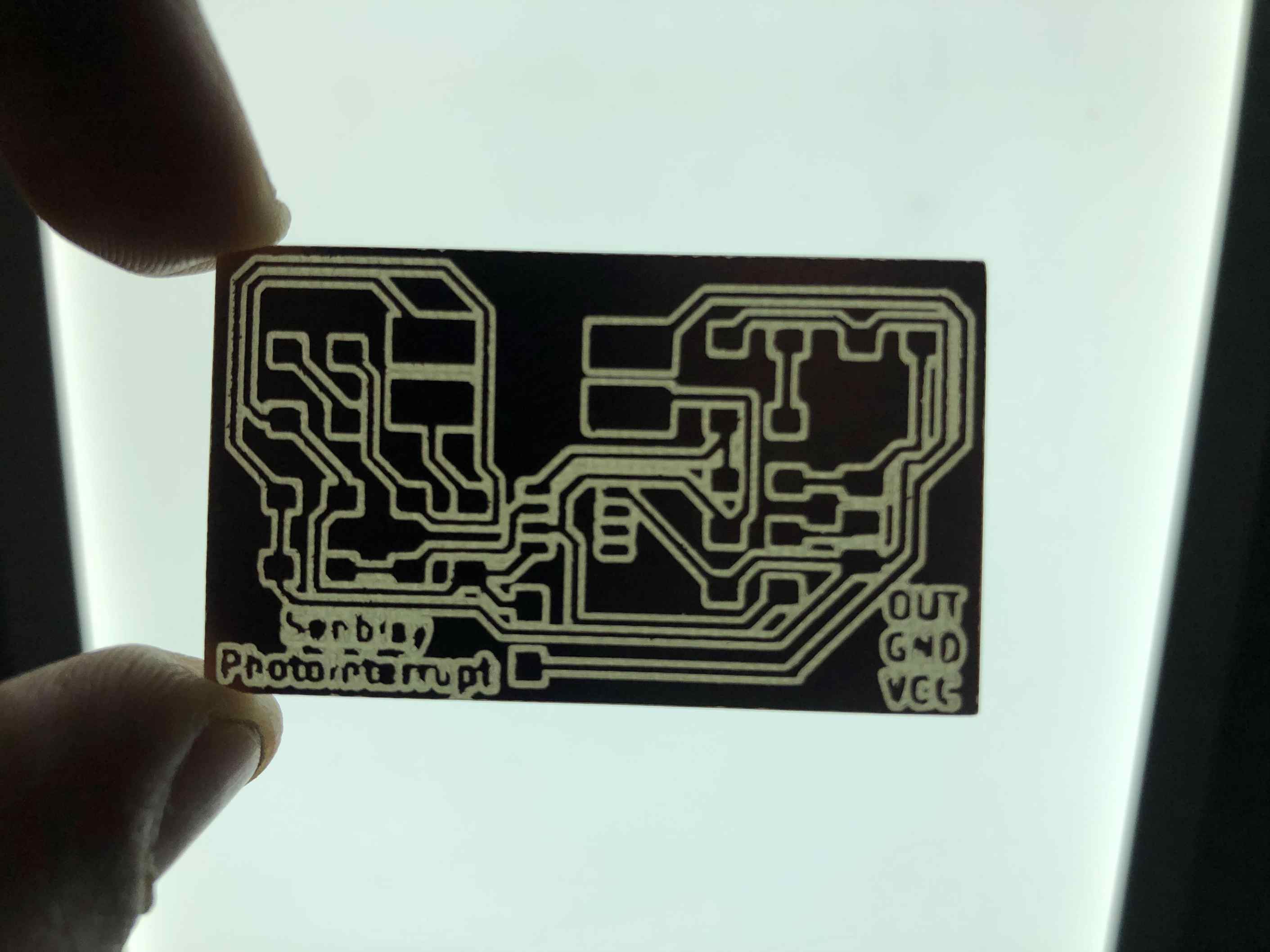
Photo interrupter PCB
After that I started soldering the components on it.
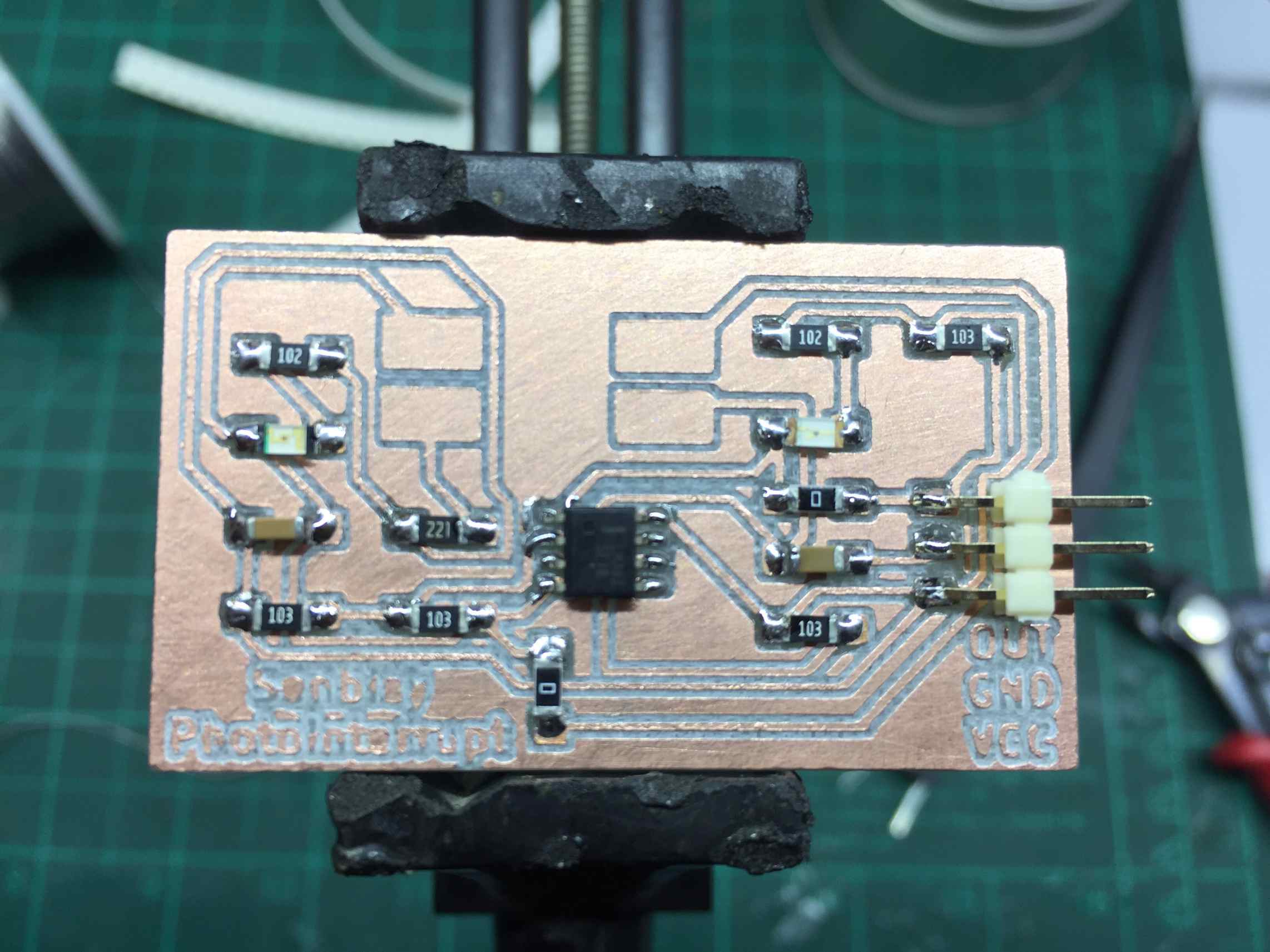
Photo interrupter PCB soldered
Actually it didn't work after all and after revising it I found that there is a GND track wasn't connected to the rest GNDs so I got a small wire and soldered it in it's place.
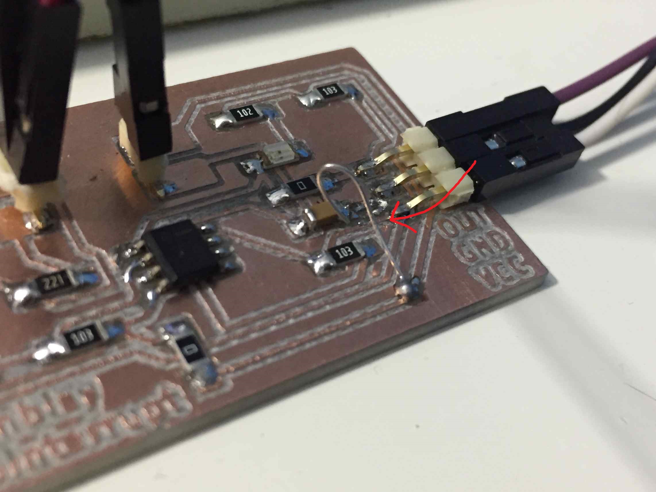
Photo interrupter error
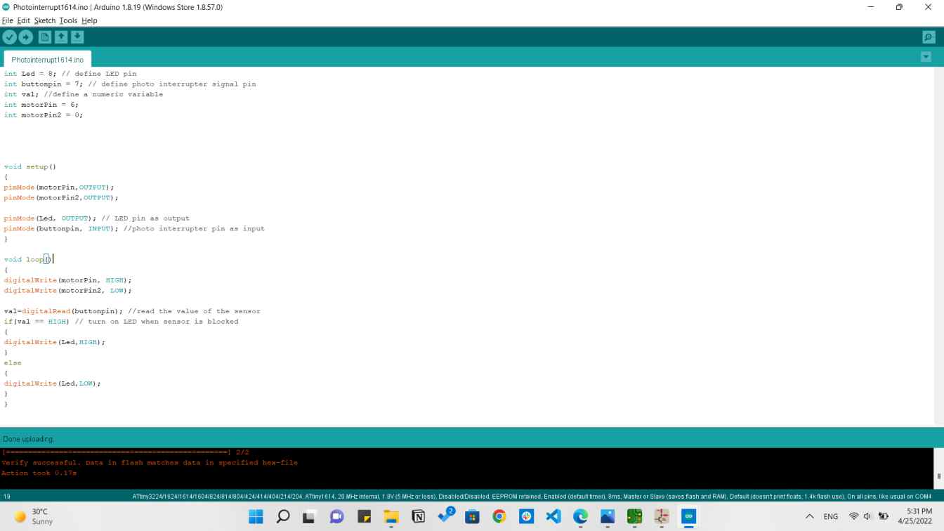
After that I typed a code that reads the input from the sensor and it came out perfectly. And I added an LED that turns ON and OFF according to the sensor's readings.
The code is very simple as it only defines the pins and determine which is input and output, then it gets the readings from the sensor and either turn the LED ON or OFF.

Photo interrupter readings
Photo interrupter sensing
Then I thought of adding a DC motor that rotates with a slotted circle attached to its shaft and put it infront of the sensor to measure the speed of the motor.
So I connected the DC motor driver board I made in output devices to the circuit as following.
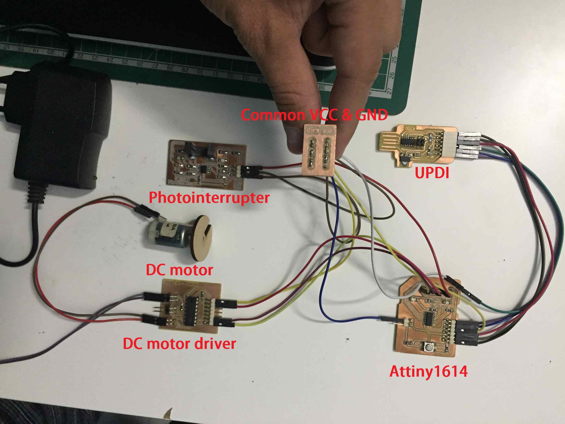
Photointerrupter and DC motor circuit
I just forgot to mention that I had an issue with the VCC and GND pins that they needed a board to gather them all together, so I made a board with 6 pins of each.
I designed this board on KiCAD.
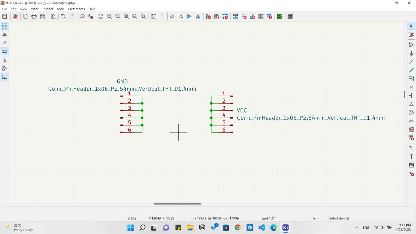
Common VCC & GND schenatic
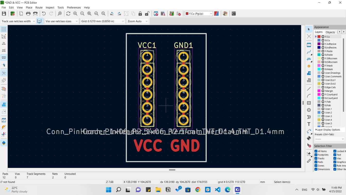
Common VCC & GND PCB
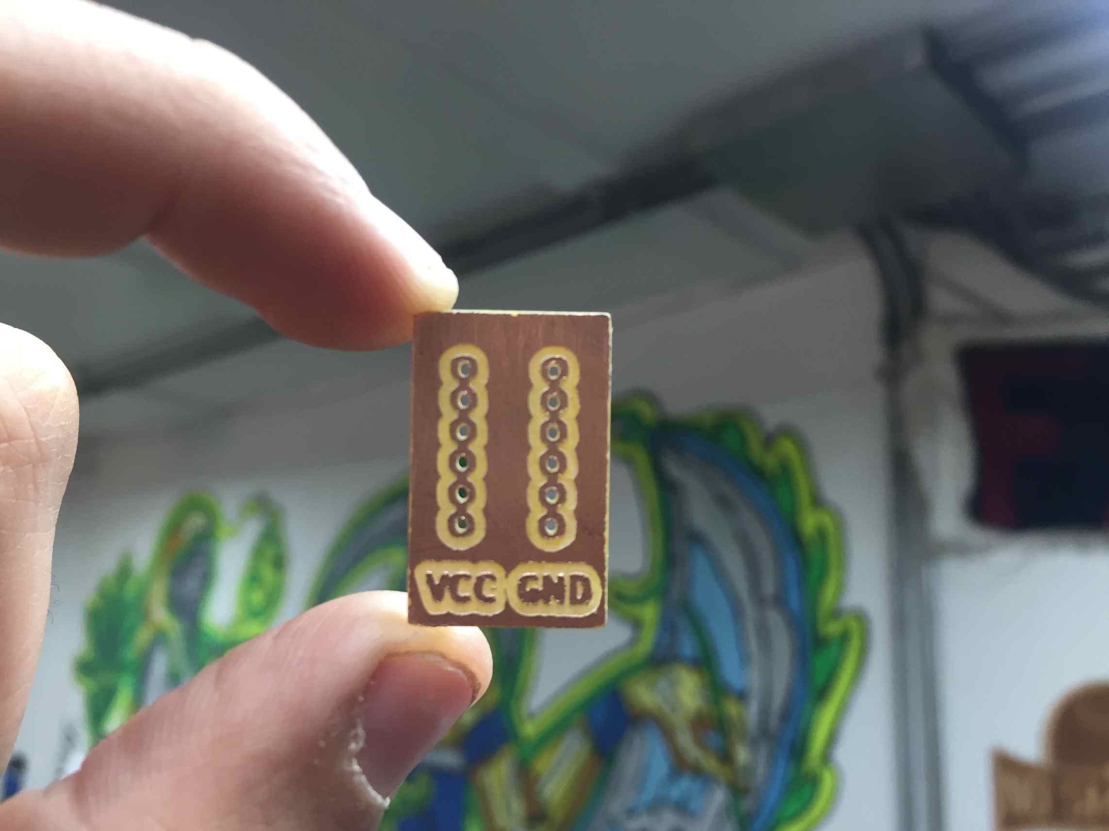
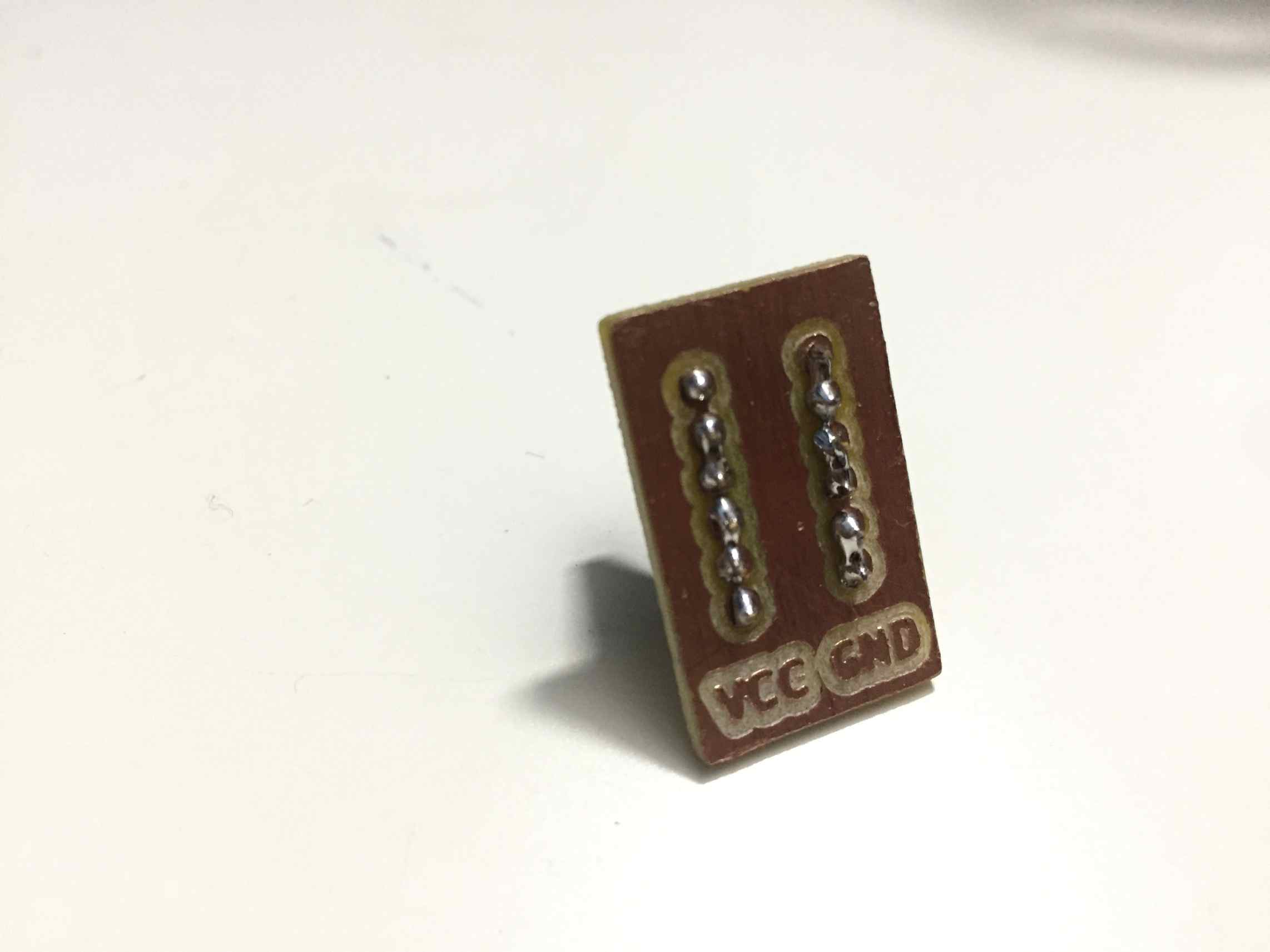
Then I started fabricating it.
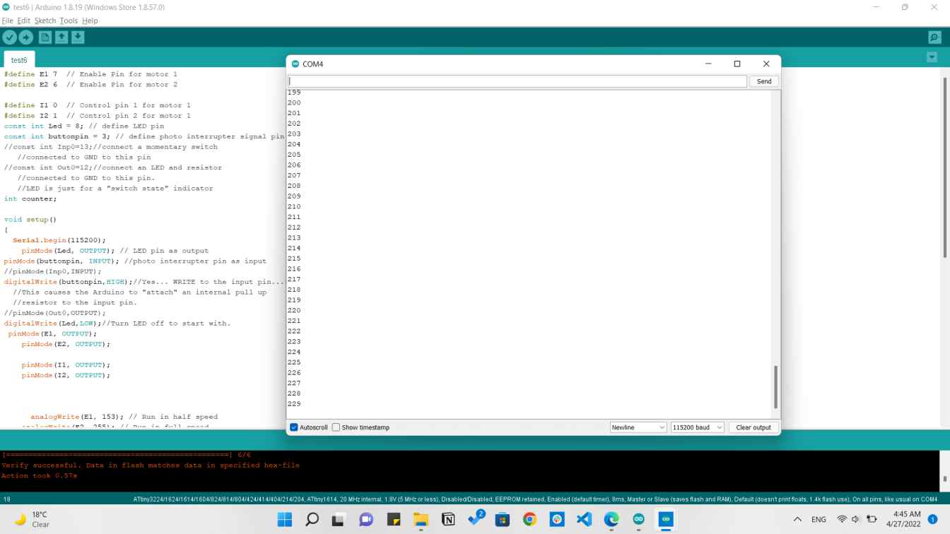
After connecting that I typed a code that operates the DC motor with a high speed and then goes to a low speed.
I just added here to the previous code a DC motor to rotate in 2 directions with different speeds.
Photointerrupter and DC motor rotating
Photo interrupter sensing DC motor
As shown that the LED blinks very fast when the motor is rotating at high speed that it can not be noticed, while it becomes noticable when the motor slows down.
The last thing was to add a counter that counts the signlas coming out of the sensor and start measuring the speed so I made the counter but I couldn't make it calculater the speed according to time.
Photointerrupter and DC motor rotating and a counter
So it just was a counter that countes how many revolutions the DC motor made.
Photo interrupter counting revolutions
Downloads