
Week 10
Output Devices
Generating output signals!!
-
Group Assignment
- Measure the power consumption of an output device Individual Assignment
- Add an output device to a microcontroller board you've designed, and program it to do something
Individual Assignment
In this assignment I need to program any output device to do something controlled by a microcontroller board I have designed. And while I designed a Attiny1614 microcontroller board to be programmed by UPDI programmer, so I decided to use it for my output devices.
So first of all I wanted to program the 2 LEDs on the board so I typed a simple arduino code and compiled it by Arduino IDE. And what this code simply does is that when it recieves a signal from the Push button it turns the LEDs high several times as the code repeats till the number is over. with a delay of 20ms in between.
First we need to program the board with the UPDI programmer, so we need to connect it via the converter.
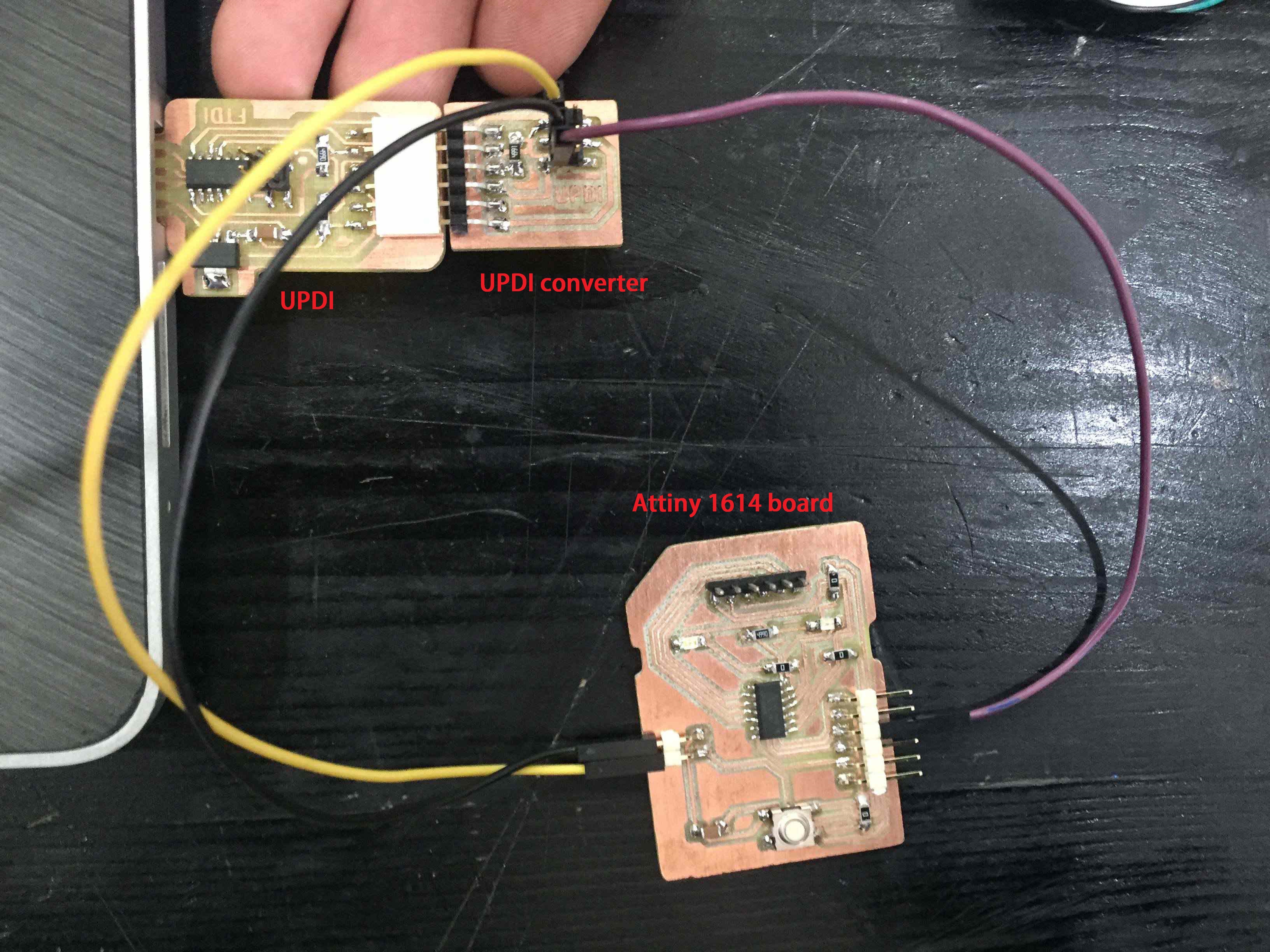
UPDI connection
And this was the output.
2 LEDs blinking
Then I thought of connecting a DC motor that operates also with the LEDs when the push button is pressed.
So I just added the deifinition of the motor's pin and made a line for its output when the button is pressed.
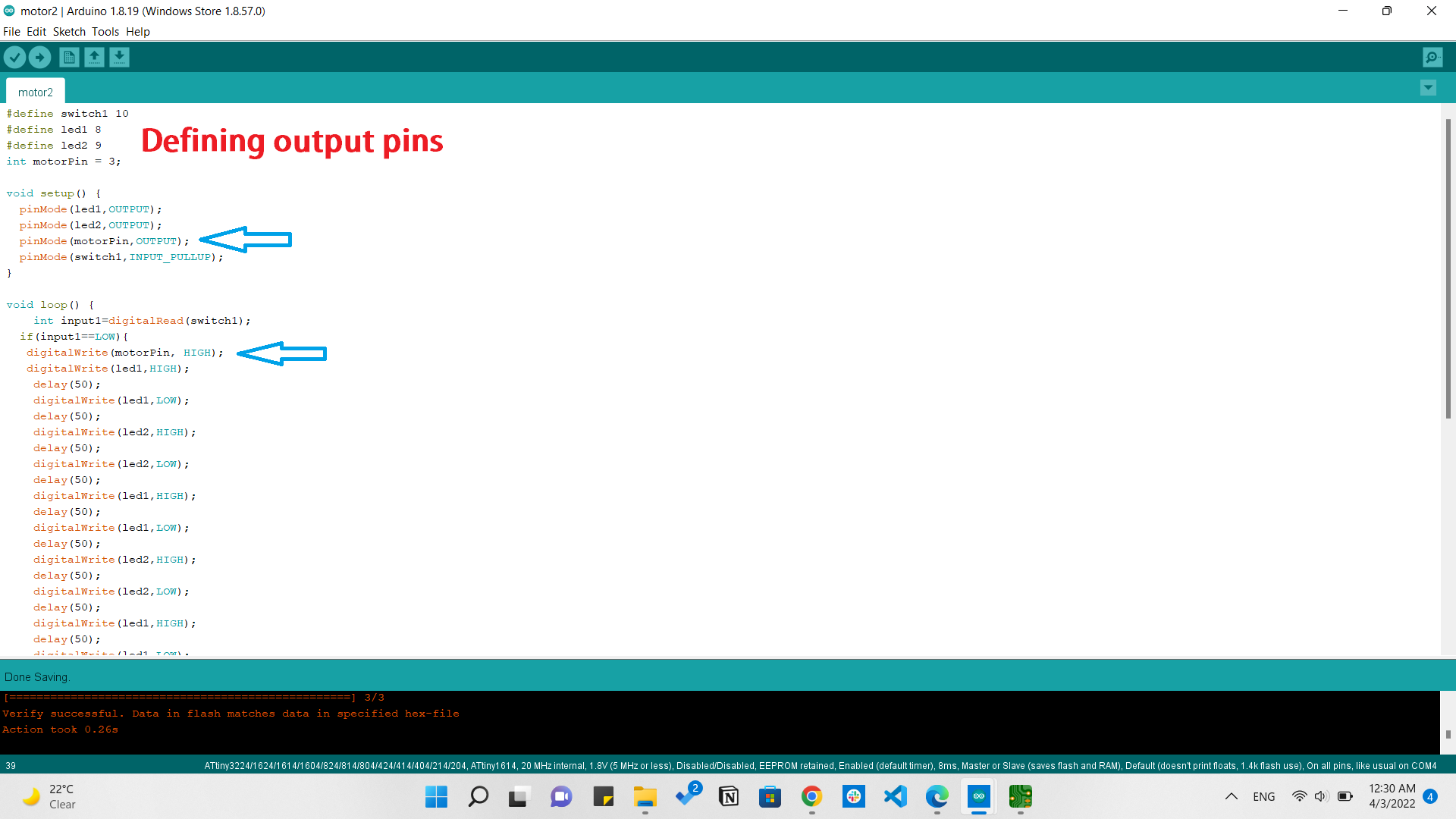
Adding the motor to the same code
And the circuit was very simple, I connected the DC motor to output1 on the L298 board, and the external power source to the 5v and GND pins, took a GND also to the 1614 board, and the output pin from the board to the IN1 on the L298.
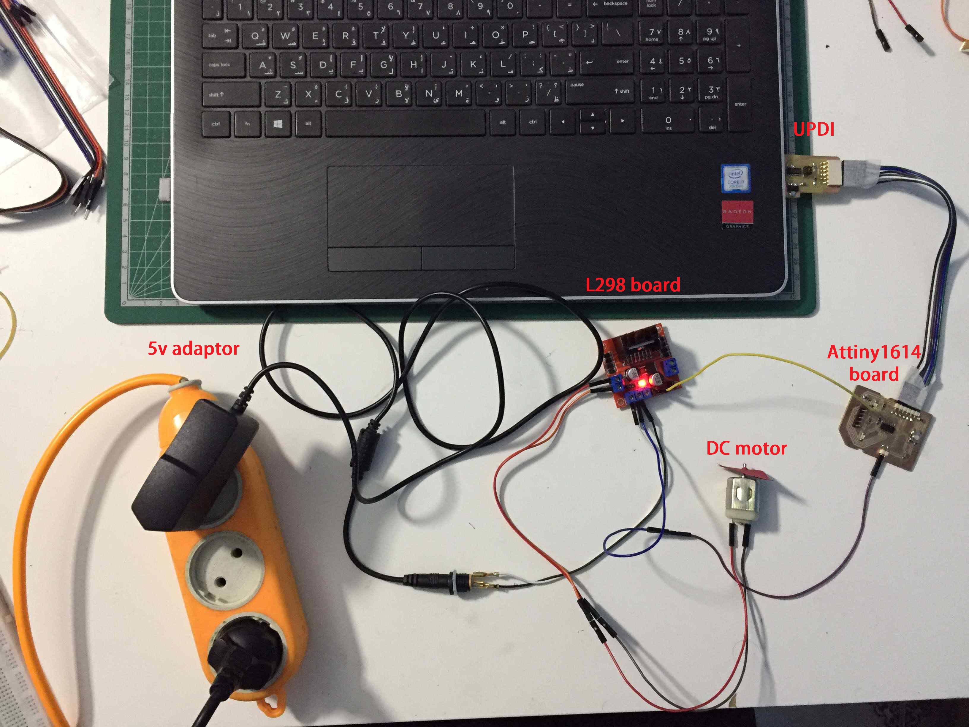
DC motor circuit
And this is a simple scematic showing just the way of connection between the DC motor, L298, and the 1614 board.
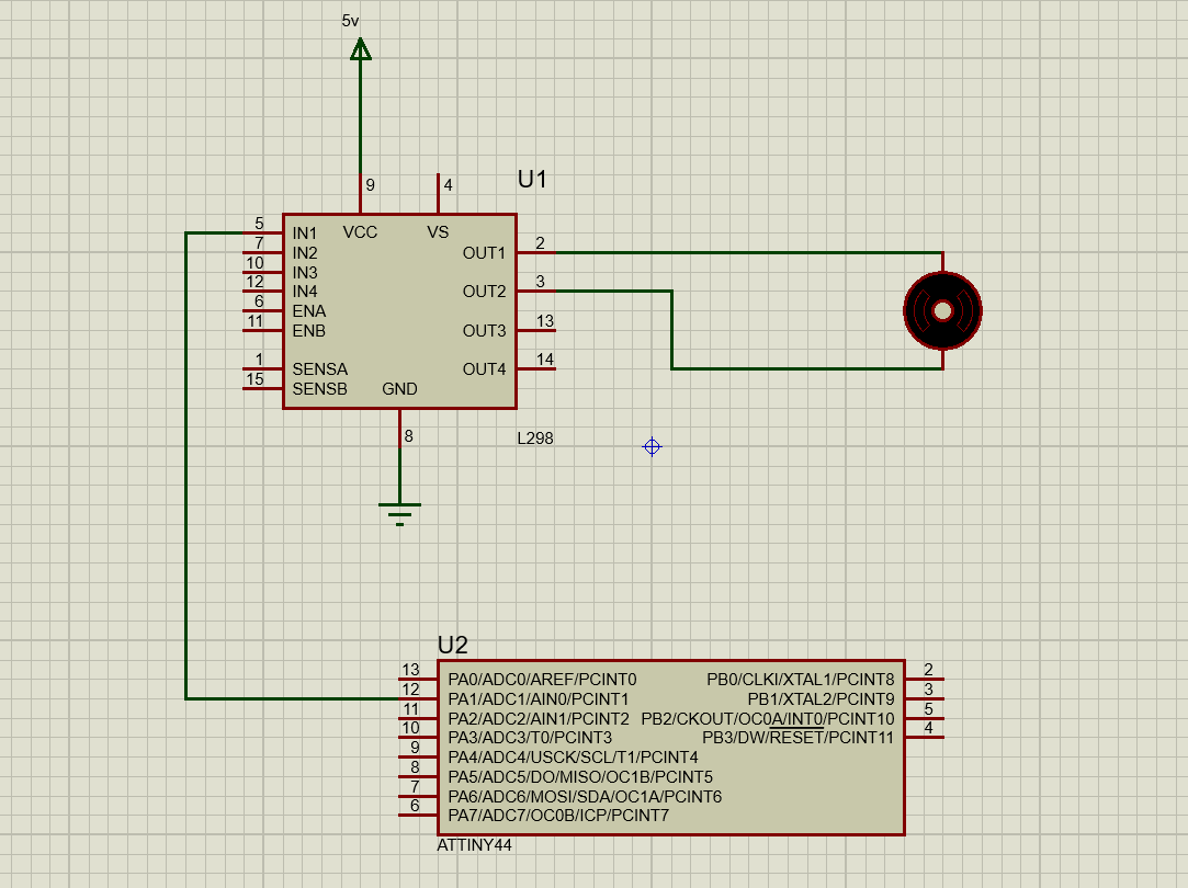
DC motor simple schematic
And this was the output.
DC motor with 2 blinking LEDs
As everything is working I decided to fabricate my PCB. So I started looking for an IC that would operate as the L298 module and I found the L293 IC.
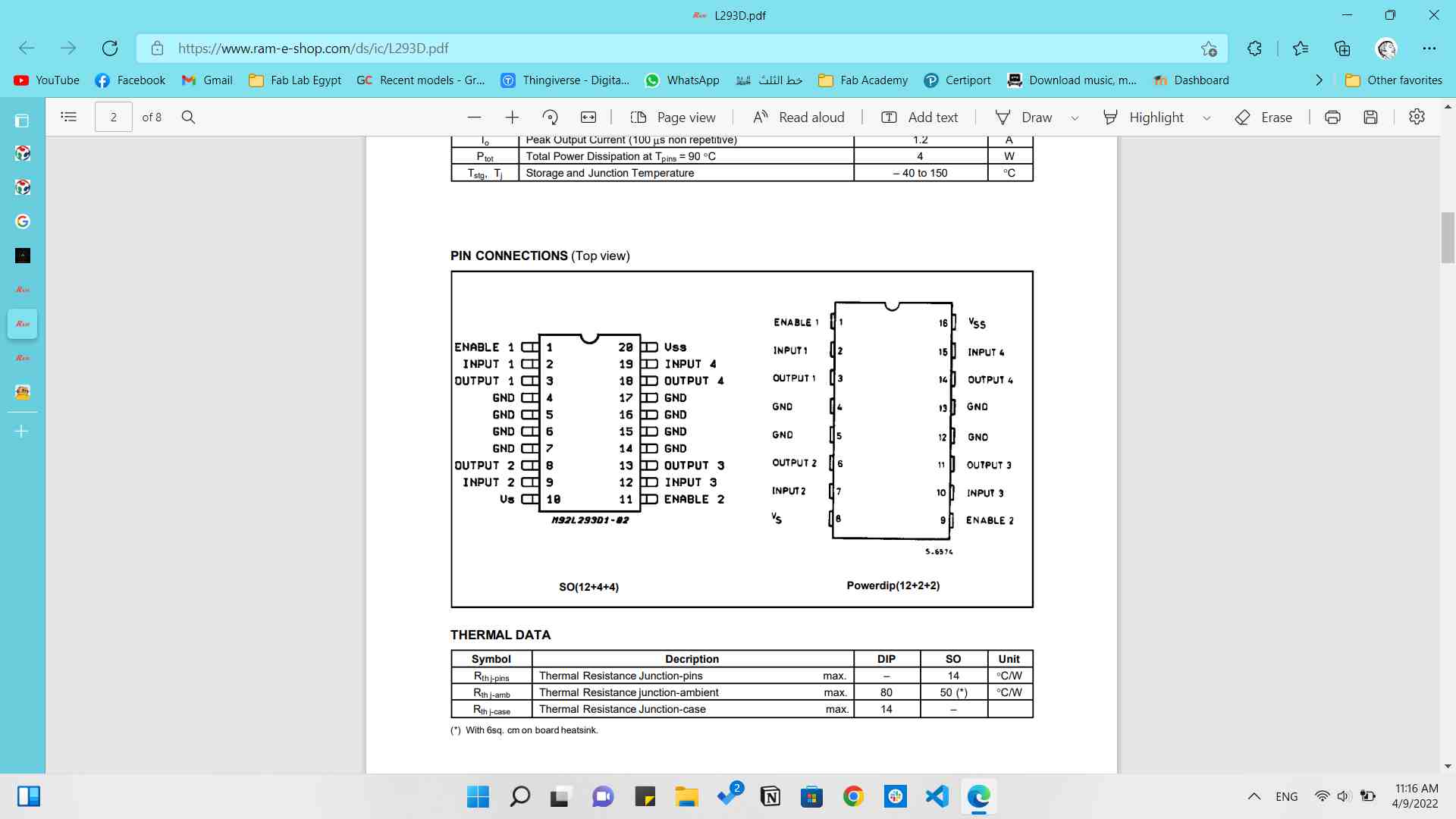
L293 IC
Now the code that I wrote was to drive the DC motor for 5000ms in one direction, stop rotating, and then rotate in the other direction for 5000ms too.
And I started designing the schematic on KiCAD, and it was so simple as it consisted of the L293 IC and just pinheaders for the power source, motor outputs and the microcontroller pins.
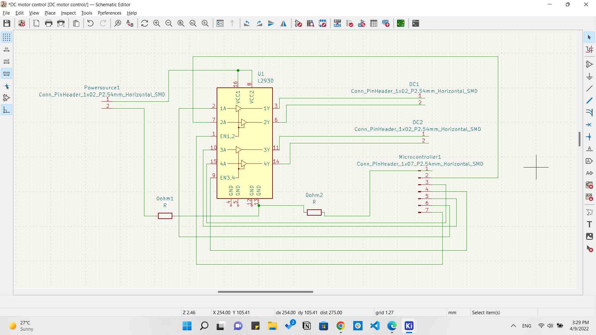
DC motor schematic
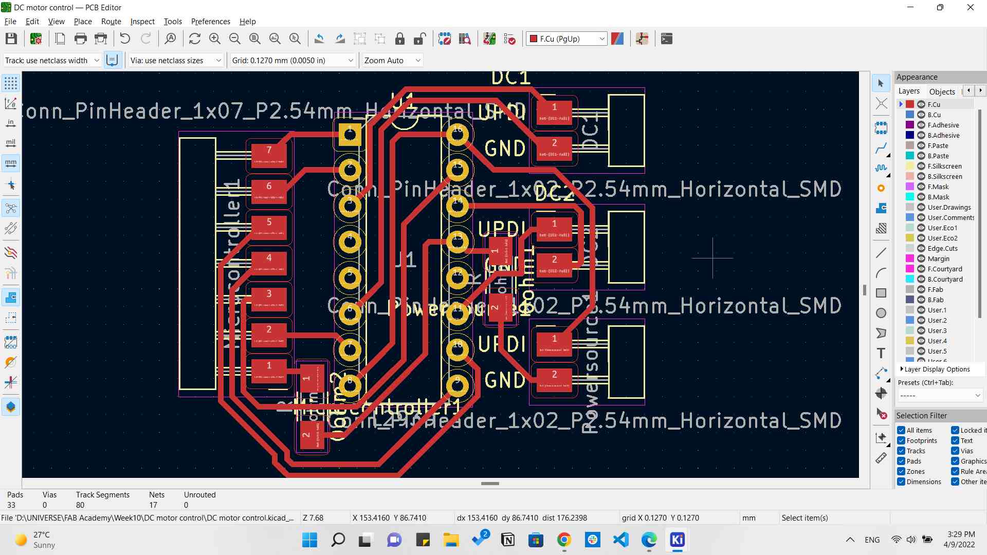
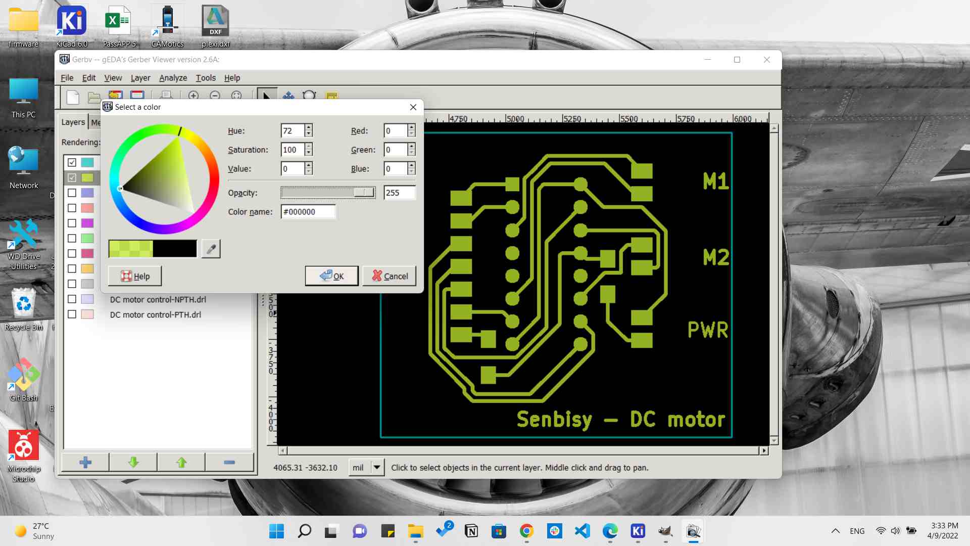
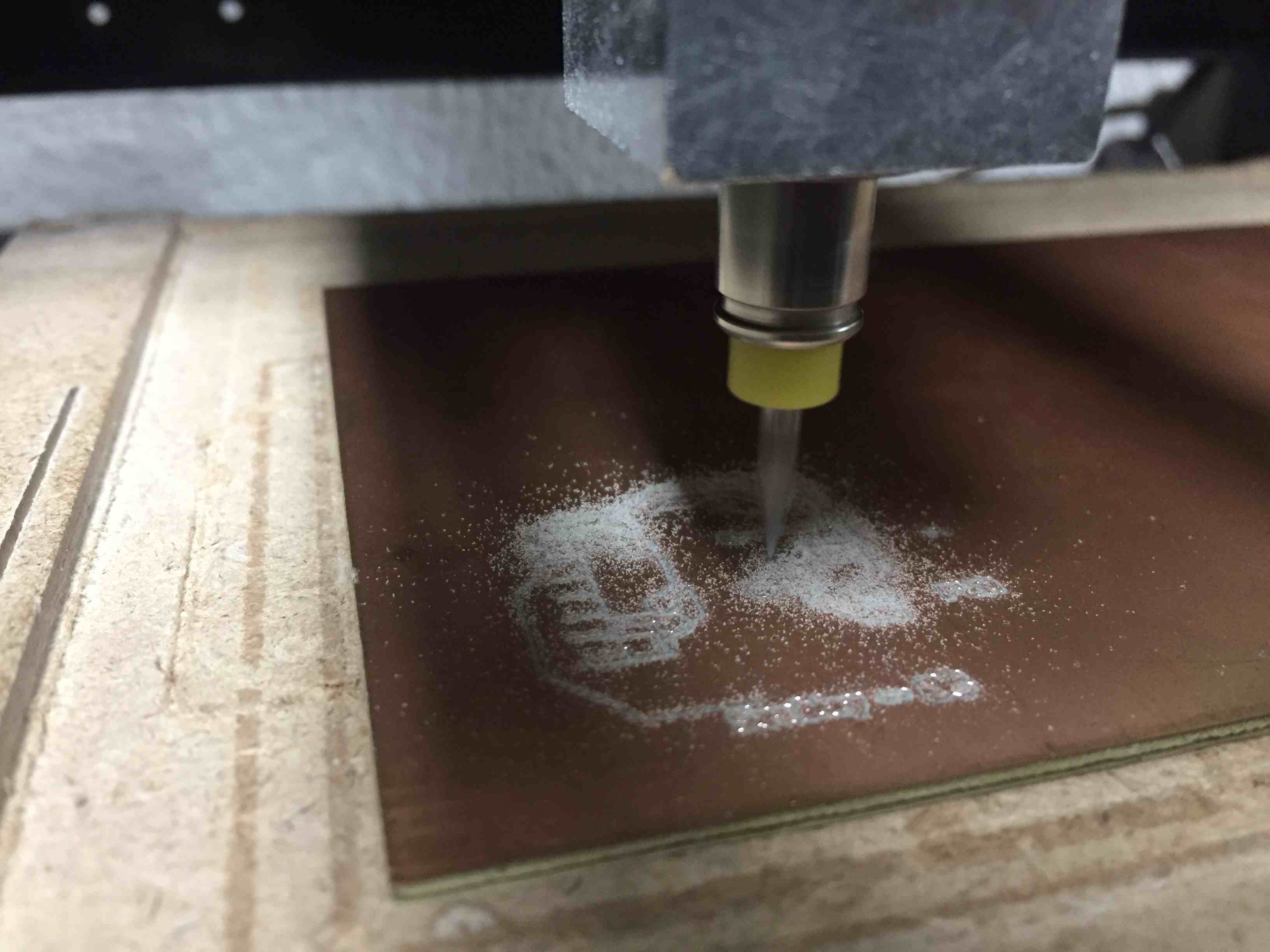
Then I strted exporting the gerber files and preparing it for milling.
Now it's time for milling the board.
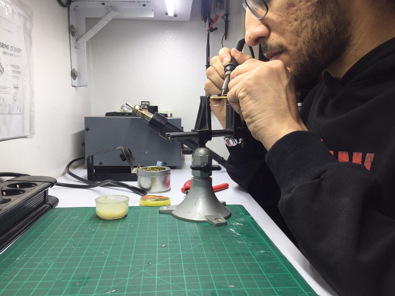
After that I started soldering the components on the board.
And this is how it came out!!
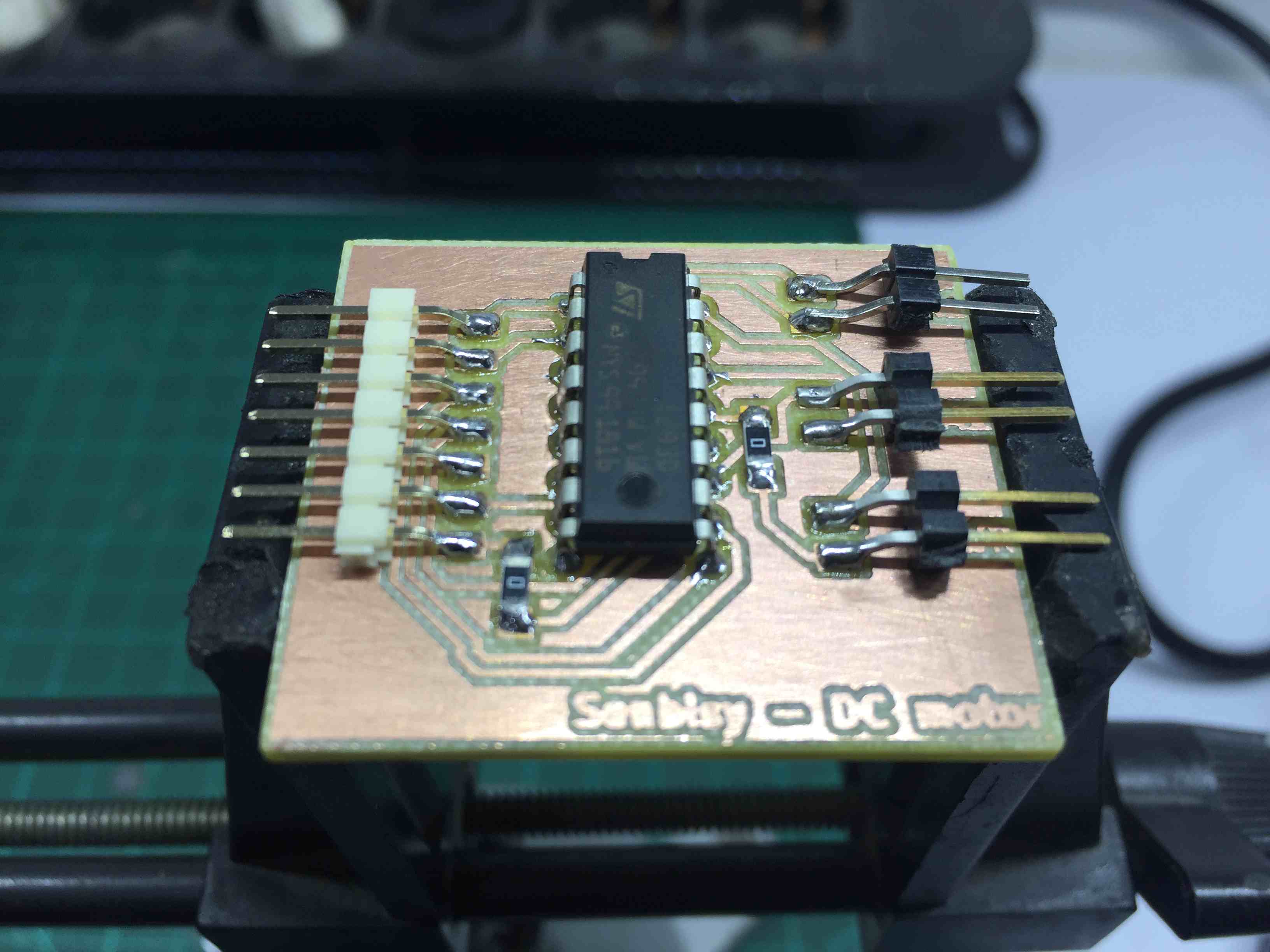
And now all we got to do is connect everything and start running the code.
Then I actually thought of making something not just high and low signals. so I started making a 7 segment counter.
First I started by typing a code for 2 7segment digits as following.
	int arrayOne [] = {0,1,2,3};
	int arrayTwo [] = {6,7,8,9};

	void setup()
	{
	for (int pin = 0; pin < 4; pin++)
	  {
	  pinMode(arrayOne[pin], OUTPUT);
	  pinMode(arrayTwo[pin], OUTPUT);
	  }
	}

	void loop()
	{
	for ( int counter1 = 0; counter1 <= 9; counter1++)
	  {
	  displayBinary1(counter1);
	  for ( int counter2 = 0; counter2 <= 9; counter2++)
		{
		displayBinary(counter2);
		delay(500);
		}
	  }
	}

	void displayBinary(byte numToShow)
	{
	  for (int i = 0; i < 4; i++)
	  {
		if (bitRead(numToShow, i)==1)
		{
		  digitalWrite(arrayOne[i], HIGH);
		}
		else
		{
		  digitalWrite(arrayOne[i], LOW);
		}
	  }
	}
	void displayBinary1(byte numToShow1)
	{
	  for (int x = 0; x <4 ;x++)
	  {
		if (bitRead(numToShow1, x)==1)
		{
		  digitalWrite(arrayTwo[x], HIGH);
		}
		else
		{
		  digitalWrite(arrayTwo[x], LOW);
		}
	  }
	}
Then, as I only have 6 output pins not 7 so I thought of adding a Decoder> to decrease the number of pins used.
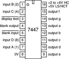
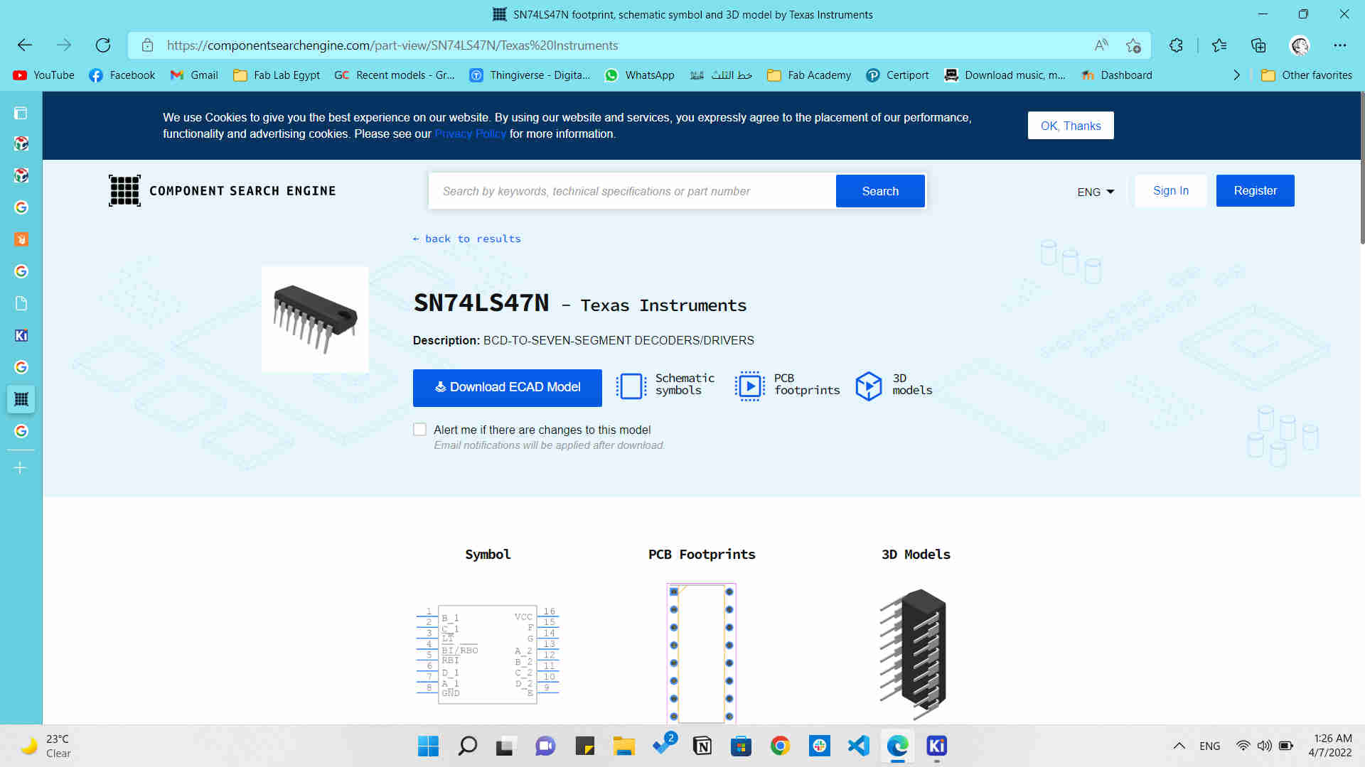
So the decoder I am using is 7447.
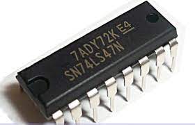
74LS47 Decoder
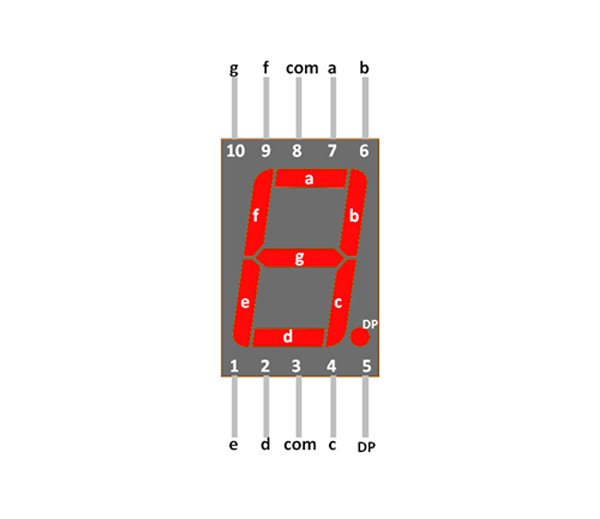
And an Anode 7 Segment.
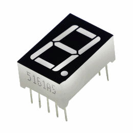
Anode 7-Segment display
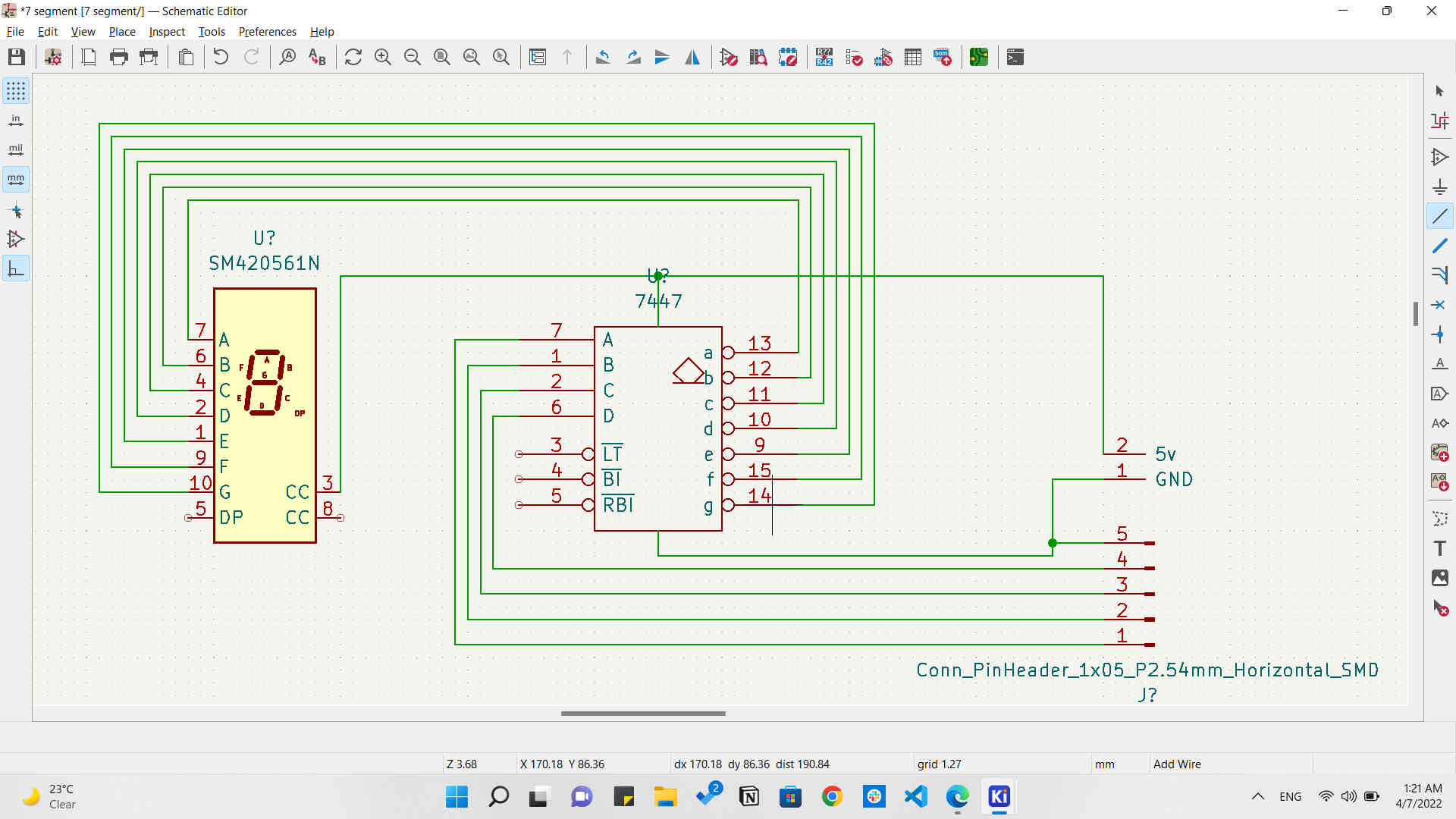
And the deal was to connect the 7 pins of the LEDs inside the display to the letters in the decoder accordingly. So a to a, b to b, c to c, and son on...
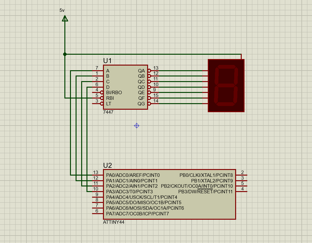
Anode 7-Segment schematic
So according to the pinout of both components, we find that we have to connect the letters to each other as prevoius schematic.
And this is how it will look like.
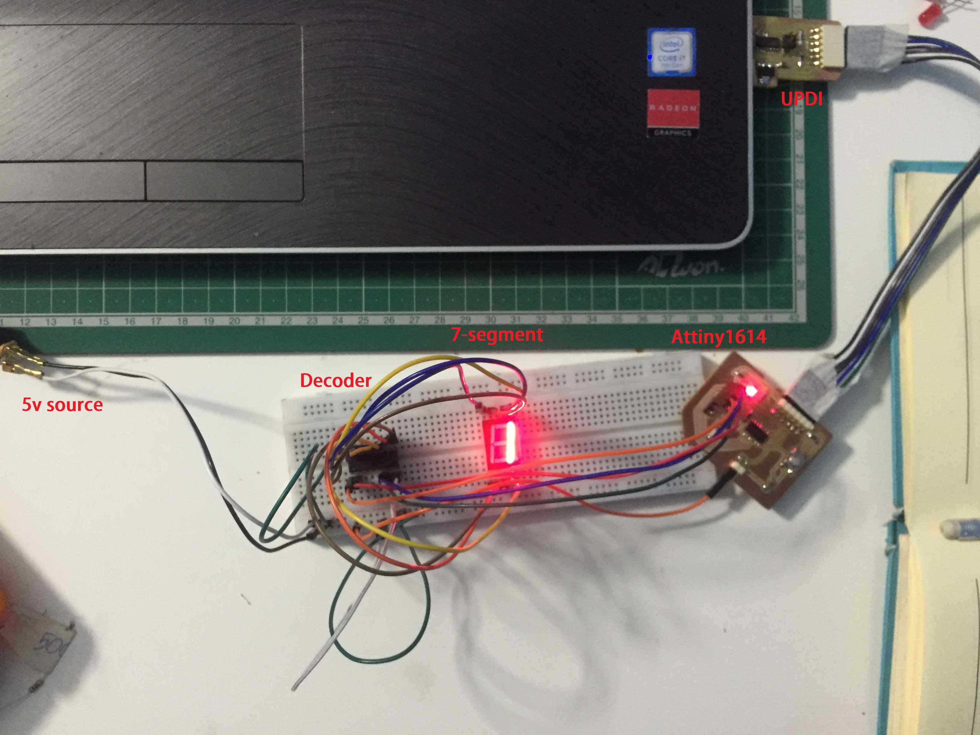
7-Segment circuit
So after uploading the code I found a seriuos issue, that the output signals were messed up. as shown.
Messed up signals
I knew that the problem was in the order of connecting the wires, but as we know that if I have 4 pins that means I have 4^4 possibilities of connections and that id 256 ways. So I had to come up with another way which was binary connection.
So I brought 4 LEDs and conneted them to the output pins from the microcontroller board and tested the output signals. And I know that the output must be as following.
Default
| A | B | C | D |
|---|---|---|---|
| On | OFF | OFF | OFF |
| OFF | On | OFF | OFF |
| On | On | OFF | OFF |
| OFF | OFF | On | OFF |
| On | OFF | On | OFF |
| OFF | On | On | OFF |
| On | On | On | OFF |
| OFF | OFF | OFF | On |
| On | OFF | OFF | On |
| OFF | OFF | OFF | OFF |
LED output truth table.
So I just connected them and started watching the output and switching couple of wires till I had the output according to the truth table.
Binary output on 4 LEDs
Then I knew which pins were A, B, C, and D. And started connected them to the 7-segment again, and it was working perfectly.
7-Segment counting
And I just wanted it to count faster...
7-Segment counting faster
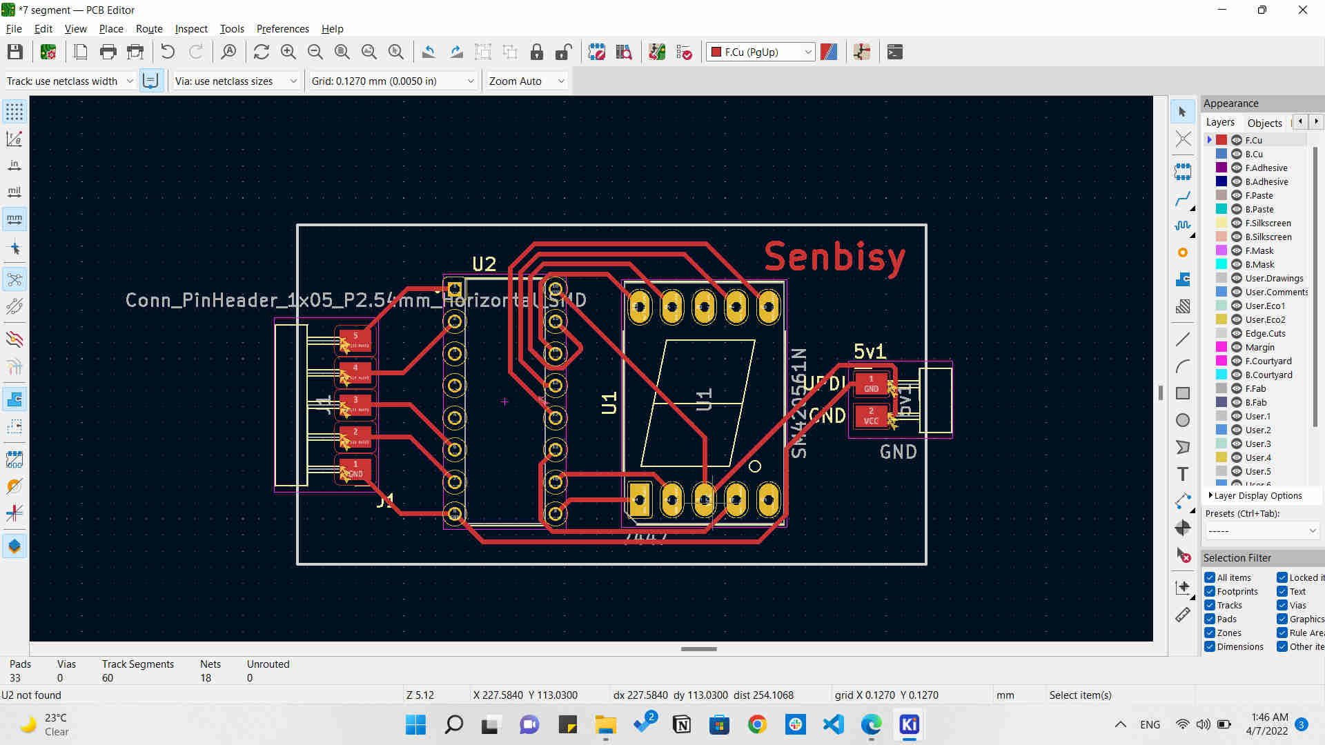
After it worked on the breadboard I wanted to make it on a PCB so I started by designing the schematic on KiCAD, and making the PCB layout.
7-Segment board schematic
But unfortunately, KiCAD didn't have the footprint for the 7447 decoder so I had to download that from Components search engine
And this was the design at the end.
Then I started milling that design on the Modela MDX-20 machine.
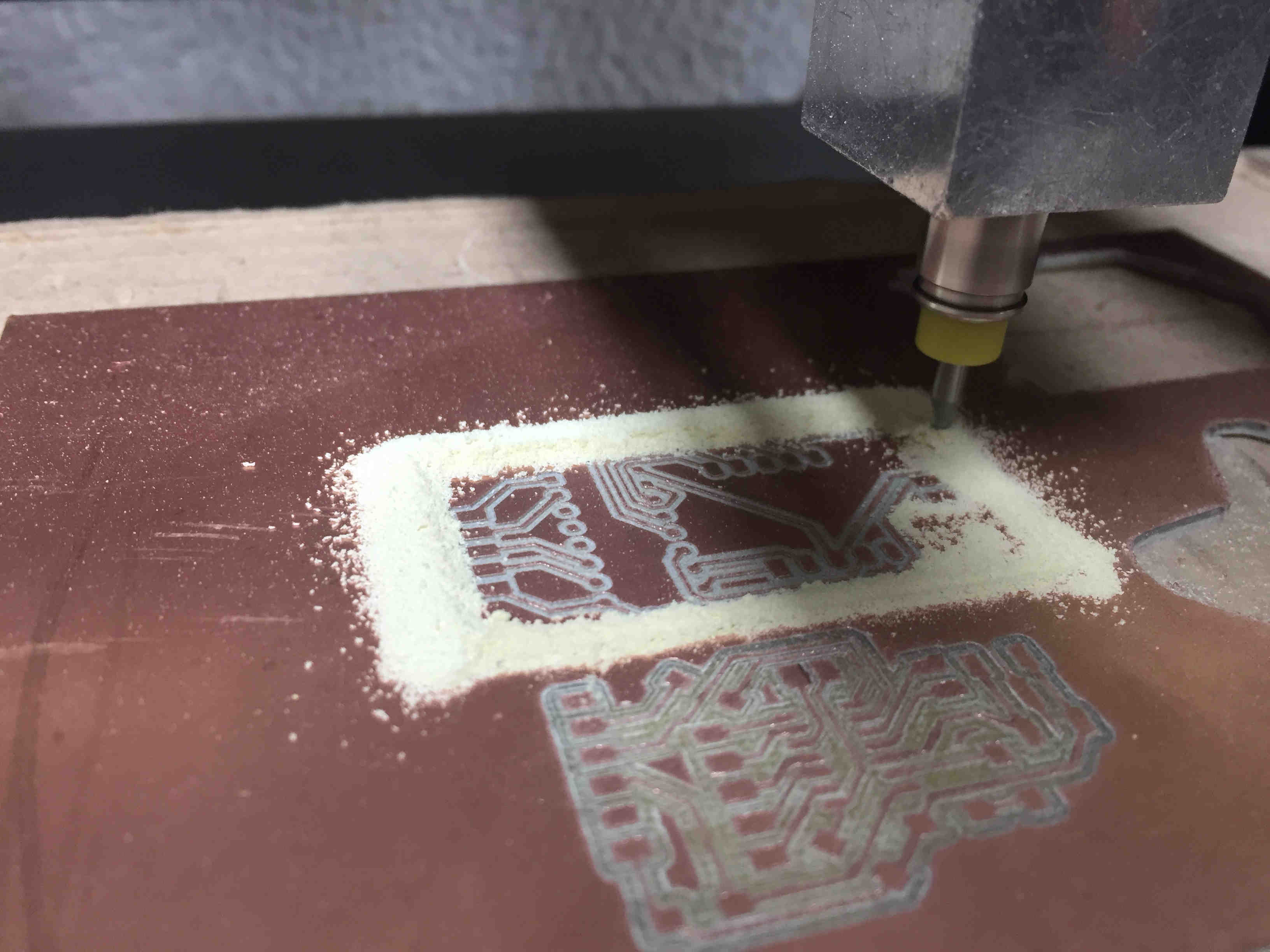
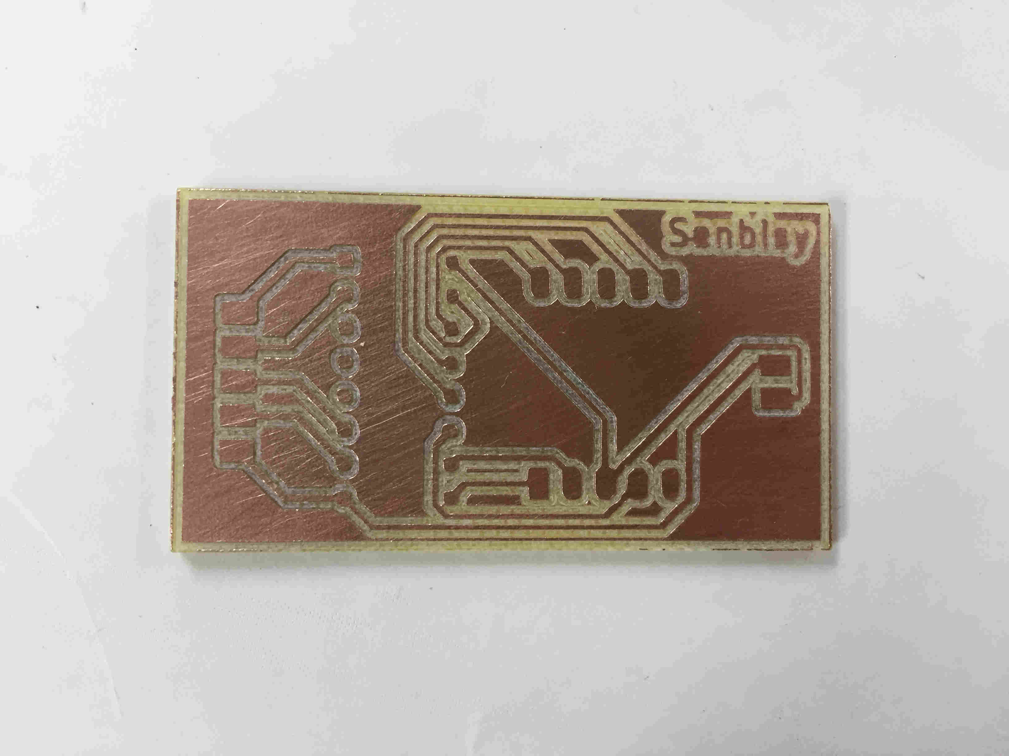
And came out with this board.
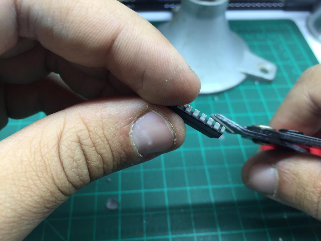
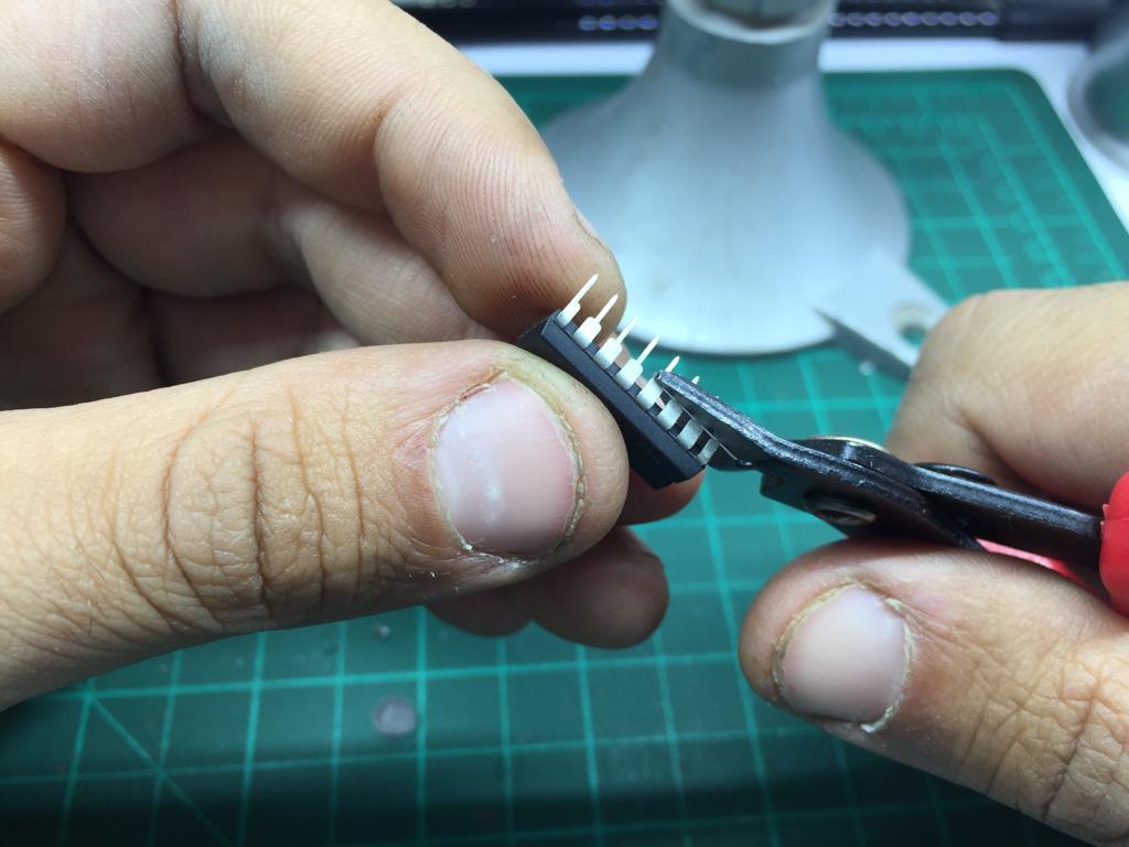
I had an issue that I knew from the begining but I kept postponing it, that the decoder and the 7-segment components are through-hole components not SMD, so I had to cut out the pins from them and just start soldering them as SMD.
Now it's all about running everything.
7-Segment board on fire