Embedded Networking and Communications
-
Group assignment:
- Send a message between two projects
-
Individual assignment:
- design, build, and connect wired or wireless node(s) with network or bus addresses
I2C Network
One of the simplest communication protocols is the I2C which is typically used for communication between components in a single device, many prefabbed sensor kits already support I2C as can be seen if they have a SDA and SCK pins like this motion sensor MPU-6500

I2C can link up to 127 devices in one net and it only requires 2 pins to operate, a clock line SCK and a data line SDA, it's a simplex communication protocol meaning a device cannot send and receive at the same time.
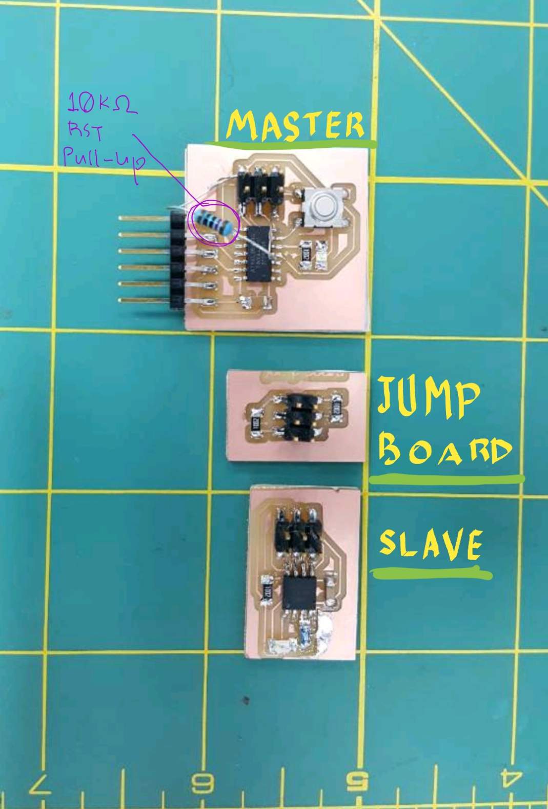
I designed two new boards, one that uses Attiny44 to be the MASTER and one that uses Attiny 45 to be a SLAVE, since I plan to use I2C protocol the SDA and SCK pins must be connected with pull-up resistors, designed an intermediate board that have two 10kOhms, one for each line connect to VCC, it also shares the power from the master with the slave board.
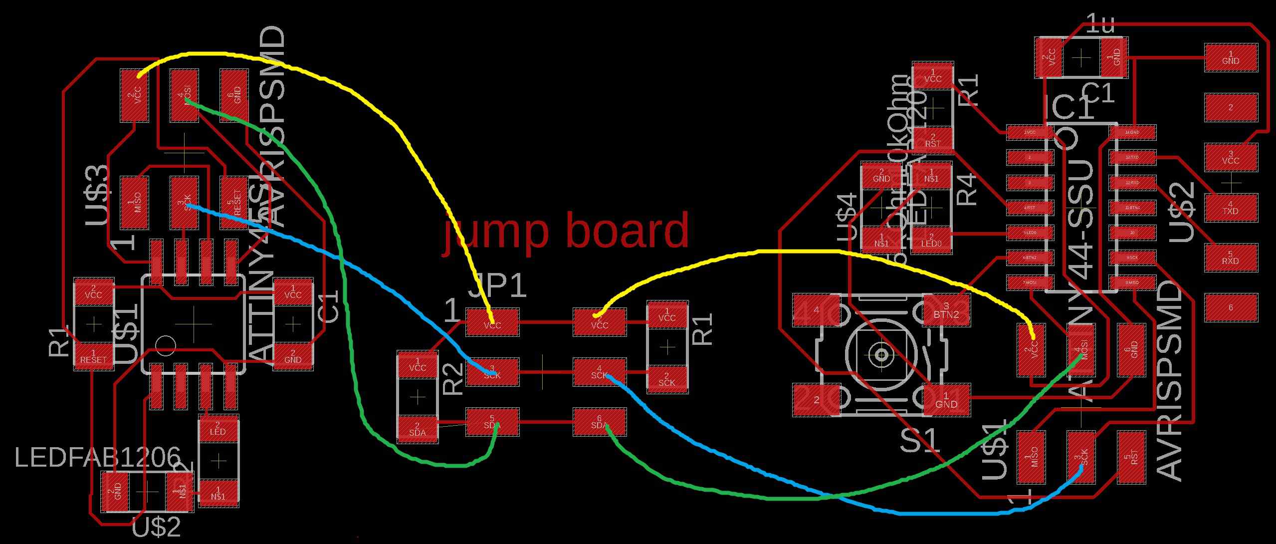
The idea is that when I press the button on the master board, communication will be opened and led on the master board will light up as the master board sends a signal to the slave board, then when the slave board receive the signal its led will also light up.
Master code:
//****** This code uses the "Attiny core" core by SpenceKonde along with its modified versions of Arduino librarries.******
// this is code for a MASTER device using the Attiny 44 controller, it sends a byte of data over I2c communication to a slave address of 8.

#include <Wire.h>             // I2C

#define ADDR   8          // address  of slave to send bytes to
#define LED 8                // ATtiny Pin 5
#define BTN 7                // ATtiny 44 pin 6 according to spec sheet, numbering is different for each core

void setup(){
  pinMode(LED,OUTPUT);
  pinMode(BTN,INPUT_PULLUP);       // pullup resistor to button pin

  Wire.begin();                    // initialize I2C lib
}


void loop(){
  if (digitalRead(BTN)==LOW){
   Wire.beginTransmission(ADDR);     //open communication line
   Wire.write(1);            // Send 1 byte, take care when entering the data type here, don't confuse values with strings.
   digitalWrite(LED, HIGH);
   delay(500);
   digitalWrite(LED, LOW);
   Wire.endTransmission();           //close communication line and stop queuing data to transmit
  }
}
Slave code:
//****** This code uses the "Attiny core" core by SpenceKonde along with its modified versions of Arduino librarries.******

#include "Wire.h"                  // wrapper class for I2C slave routines
#define I2C_SLAVE_ADDR  8            // i2c slave address (8)
#define LED         4              // ATtiny Pin 1 on attiny 45

void setup(){
  pinMode(LED,OUTPUT);

  Wire.begin(I2C_SLAVE_ADDR);      // init I2C Slave
}

void loop(){
 byte x = 0;
 if (Wire.available())
 {
    x = Wire.read();     // get the byte from master
        if(x != 0 ){

          digitalWrite(LED, HIGH);     //red led= receive
                delay(500);

        }
      else digitalWrite(LED,LOW);
 }
       digitalWrite(LED,LOW);

}
the master board sends a "1" as a value, when the slave receive a signal that is not a zero, then its led will light up.
Network in action:
Troubleshooting
After programming the boards I noticed that my master board is not functioning as expected since it only ran the code once and didn't loop, upon examining I found out I forgot to add a pull-up resistor to the reset pin on the attiny44, I fixed the issue by soldering a thru-hole 10kOhm resistor between VCC and RST on the ISP headers.