
**************************************************************************
Individual project
- Make (design+mill+assemble) something big
Group assignment:
- Complete your lab’s safety training
- Test runout, alignment, speeds, feeds, and toolpaths for your machine
- Document your work to the group work page and reflect on your individual page what you learned
*************************************************************************
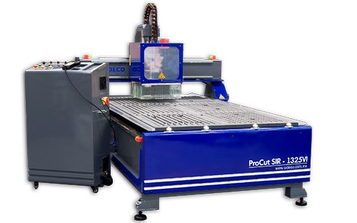
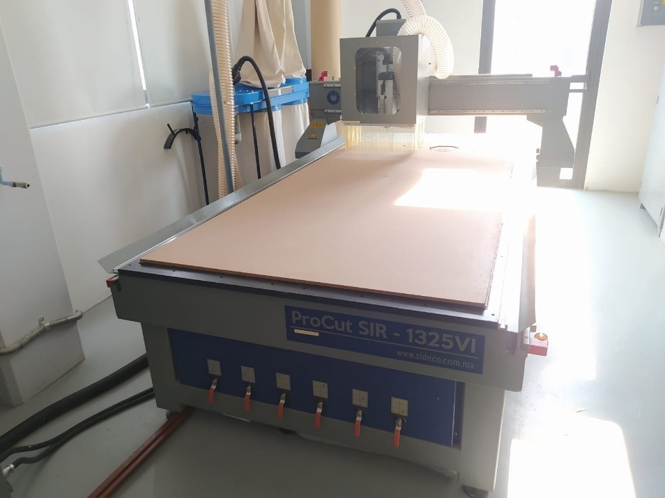
This week will focus on large dimension machining. I will use the SIR-1325VI CNC equipment of the SIDECO brand.
These are its technical specifications.
- POST PROCESSOR Artcam / Visual Mill / Type3 (not included) (I will use Fusion)
- CONTROLLER: Weihong
- COMPATIBLE SOFTWARE CorelDraw, AutoCad, Illustrator, among others.
- COMPATIBLE FORMATS: .dxf, .ai, .eps, .dwg, among others.
- ENERGY CONSUMPTION: With vacuum pump 18.5 KW
Without vacuum pump 7.5 KW
- VOLTAGE: 220 V Three-phase
- MOTORS: SIR-1325VI Servo Loop motors, max movement speed 35,000 mm/min.
- X,Y AXIS TRANSMISSION Helical rack and pinion and Hiwin/Abba high precision guide rail (Taiwan)
- SPINDLE SPEED 10000 – 18000 RPM
You can check the group assignment HERE
1. Design and Modeling.
For this step I used Fusion 360 since it is currently the software used in the Fab Lab to work on computer-aided manufacturing. This software is very powerful as it allows you to perform multiple operations in one place, I'm glad I discovered this software on Academy. Time to put my skills to the test with this program.
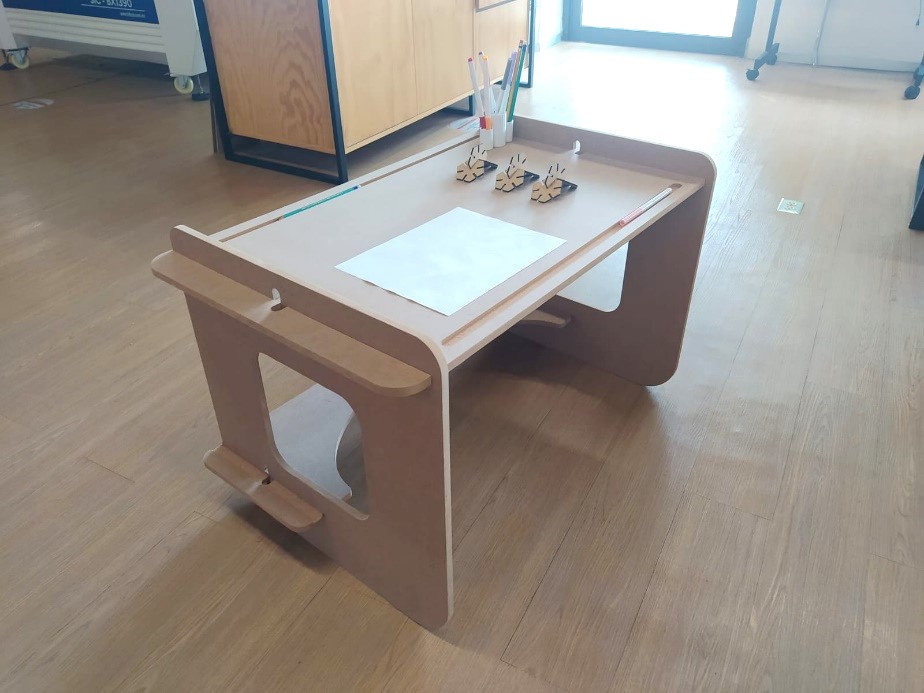
I have decided to make a desk for children from 3 to 6 years old since my FINAL project will be a multipurpose piece of furniture for children of these ages, I think it will help me to finish establishing the manufacturing process of the final project.
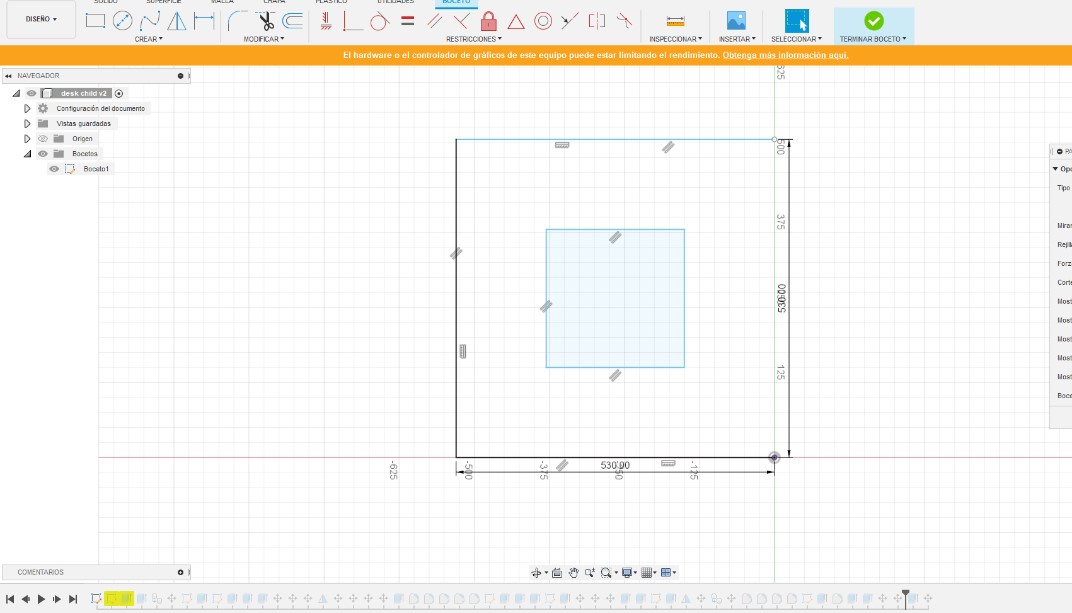
The first thing I did in Fusion was to create the individual sketches for the furniture creation.
2. In addition to the content that Niel provided us with in the Academý Calendar, I used this material as a reference for the design of the pieces.
TUTORIAL
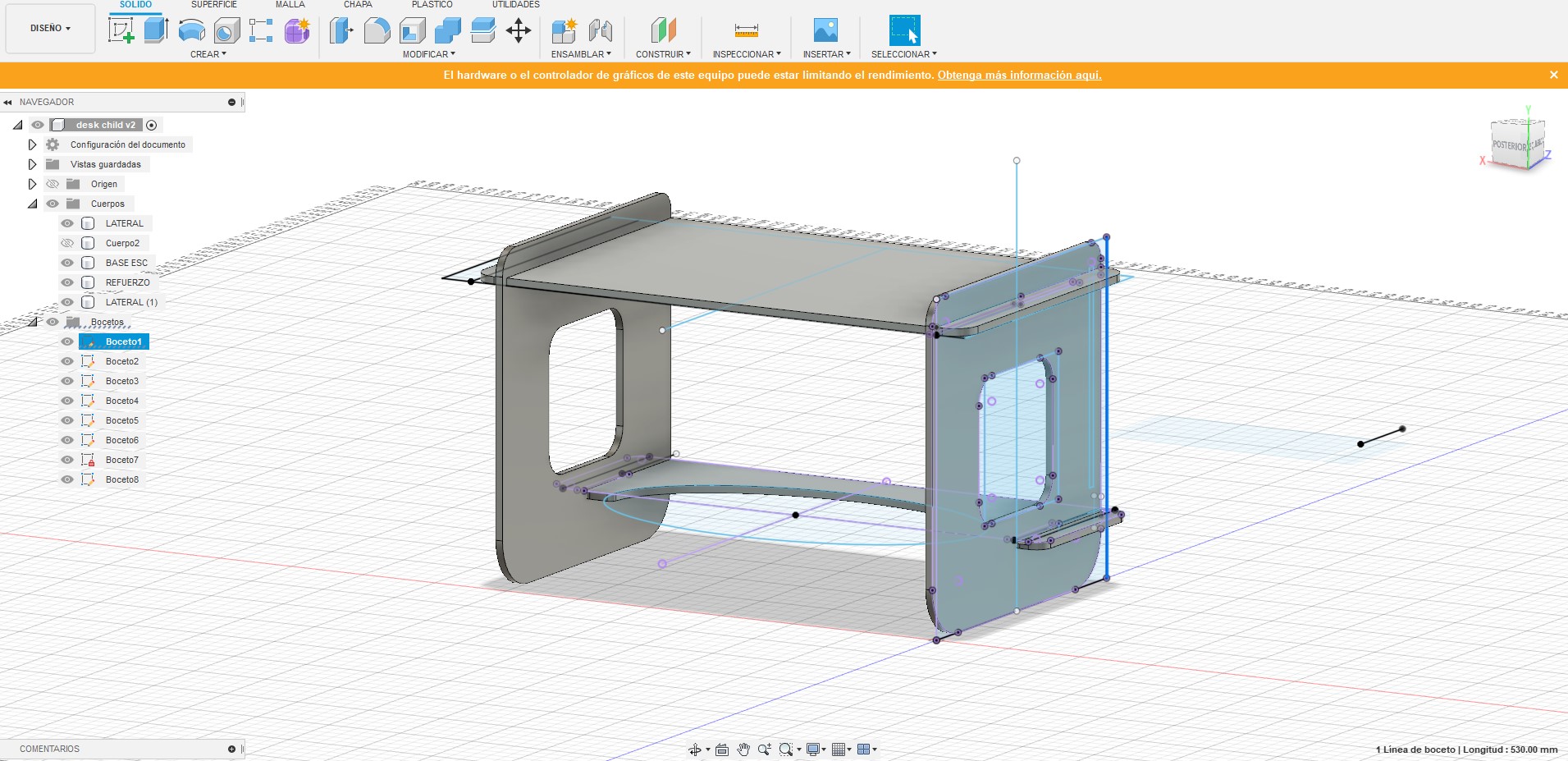
The next step was to extrude the sketches and make the assemblies with the move tool, I made some variations compared to the original sketches.
The preliminary result was as follows:
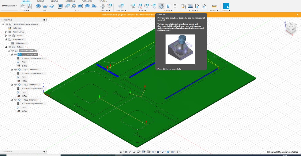
3. Once the design was ready, the next step was to arrange the pieces in a single plane and organize according to the dimensions of the MDF 2440mm x 1220mm x 15mm
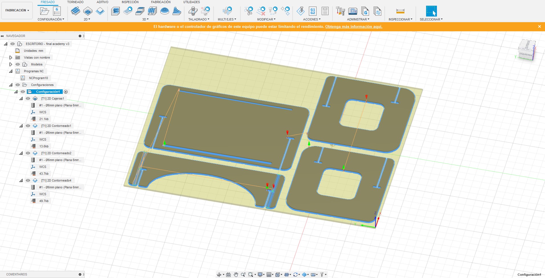
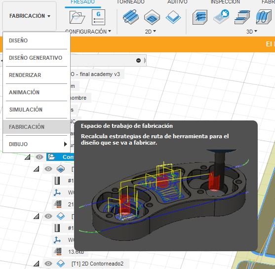
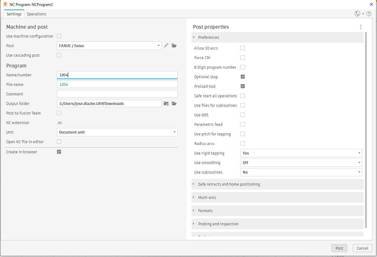
4. The following tutorial was very helpful for me to carry out the CAM process, for this I had to change the design interface to Manufacturing.
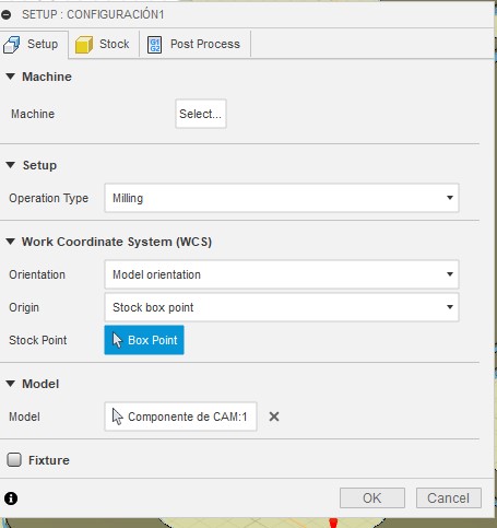
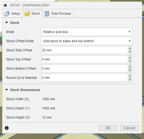
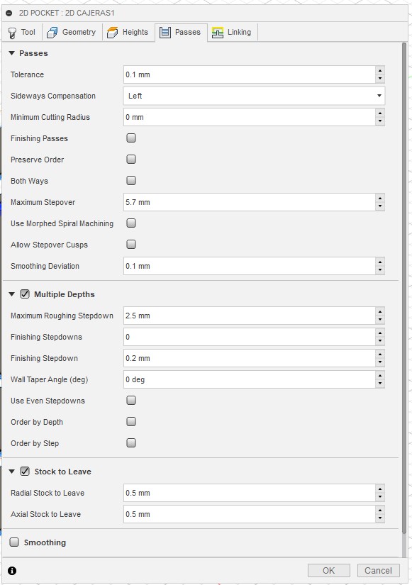
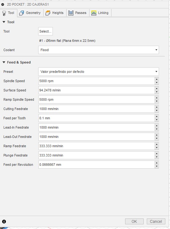
These are the settings I used to make my prototype.
5. Once we configure each Fusion process, it will give us the option to preview a simulation of the machine trajectories.
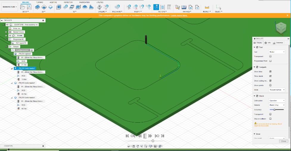
6. After validating the virtual simulation we can generate the GCODE to proceed to the manufacture of the parts.
This was the setup I used.
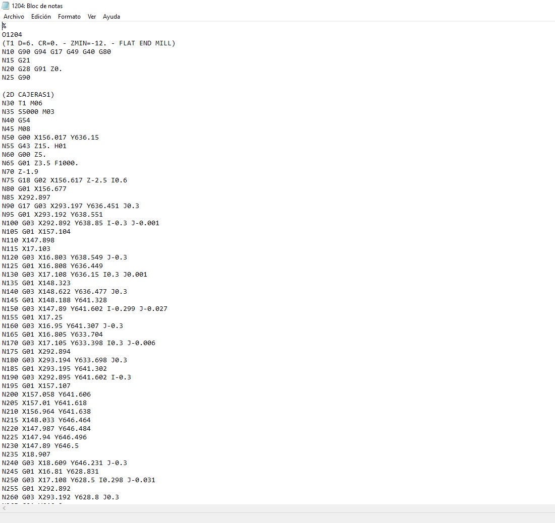
7. Once the G Code is generated, we can open it with any text editor to know each of the steps that the machine will execute.
8. Now it's time to move on to the machine. The first step was to turn on the equipment and mount the MDF board
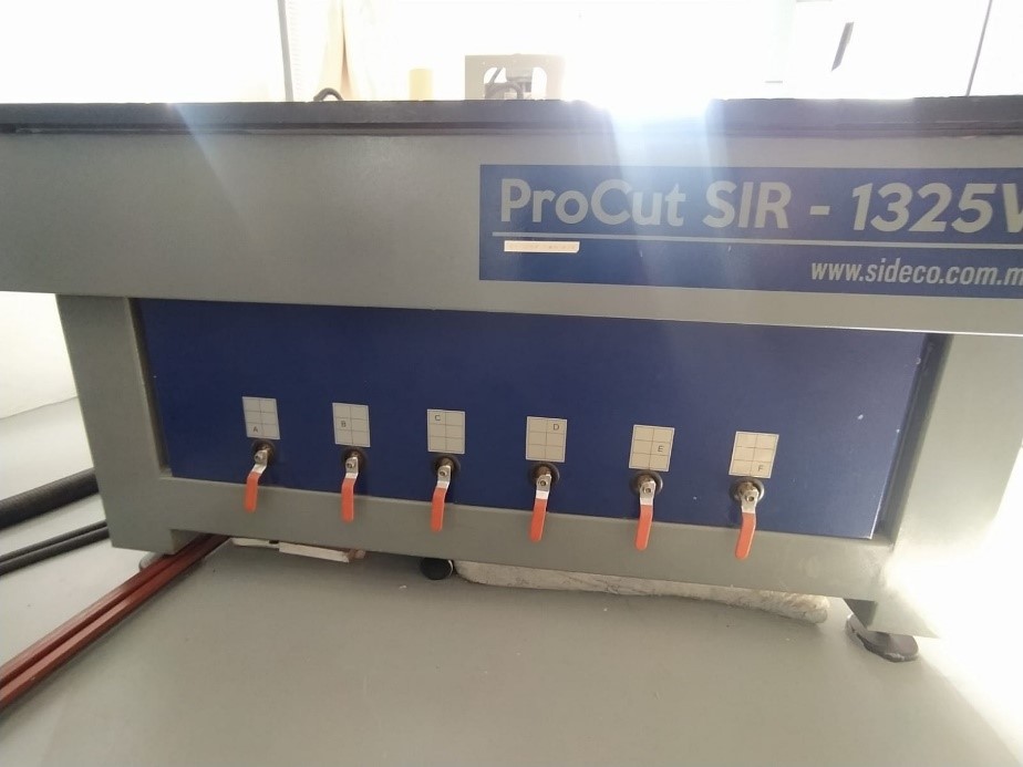
9. This equipment has a suction system with 6 suction cups, this greatly facilitates assembly since you only have to center the plate and activate the system.
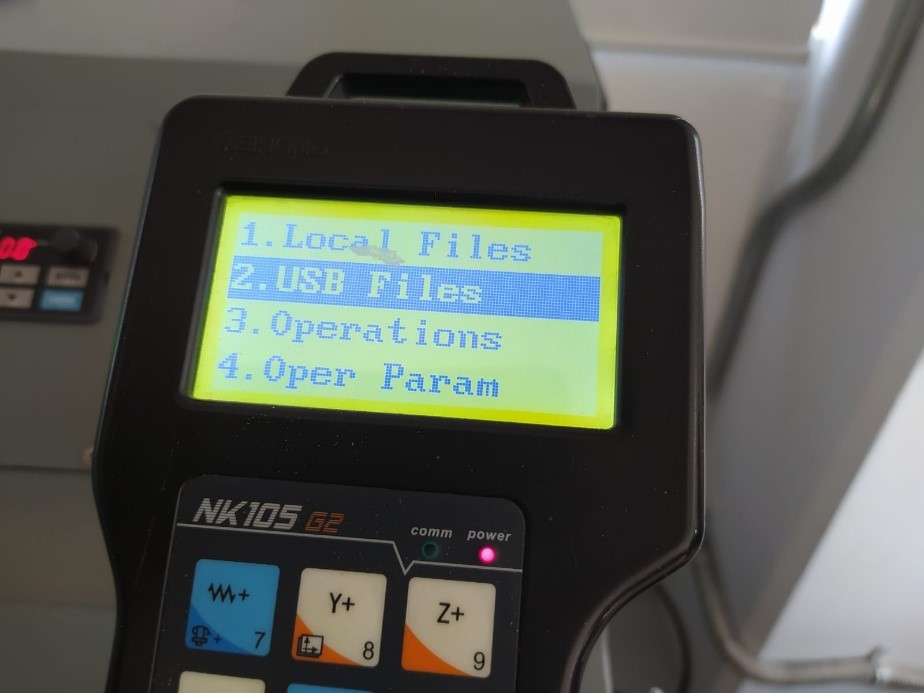
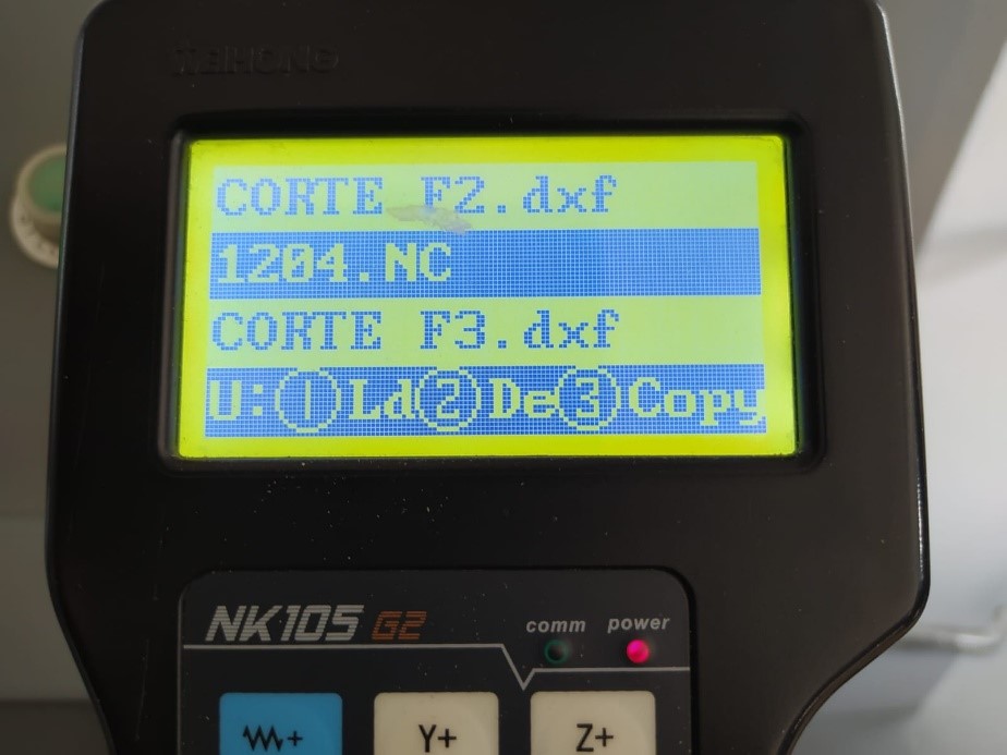
10. I saved the G code on a USB drive, so the next step was to upload the file to the internal memory of the machine
11. Then I assigned the origin of the cut in reference to the origin that I configured from fusion 360, the assignment of Z must be done very carefully, for this there is a function called "step by step" that makes movements at every .1mm, once assigned the origin with the correct tool we can send our G code to be cut (before sending it, carry out a test assigning a Z at 50mm height of the plate just to verify that everything was as configured in fusion.
12. Click Start to start the action (finally)
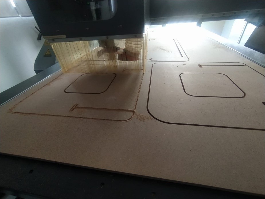
13. The equipment has a dust extraction system, although many residues remain at the end of the cutting process, it is advisable to vacuum all the residues before removing the plate.
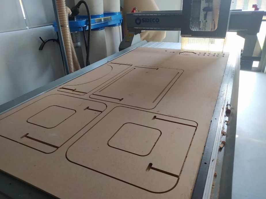
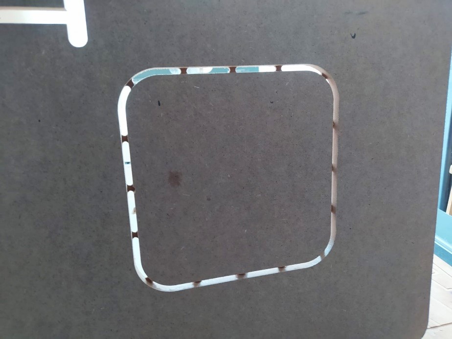
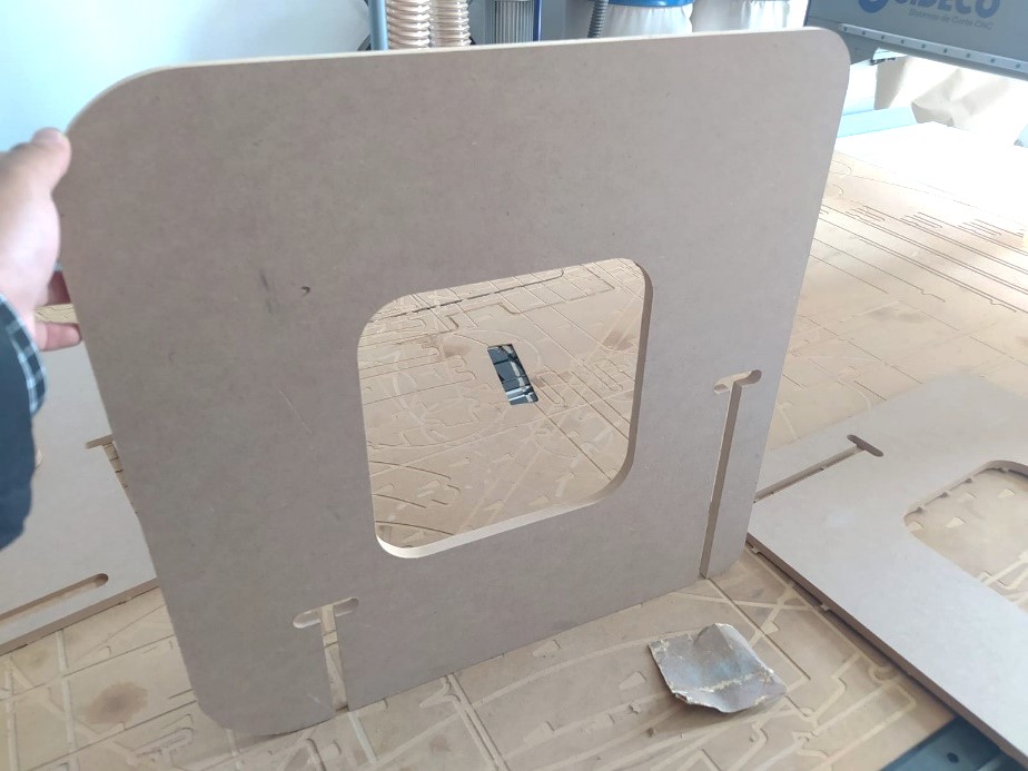
14. Upon removing the plate I found that everything went pretty well, one tip I can give you for best results is to include these jumpers that prevent the cut pieces from coming off the plate. It is very easy to configure them from here:

15. The penultimate step was to sand the residue from these bridges, and vacuum the pieces prior to final assembly, the design was intended to require no glue or screws.
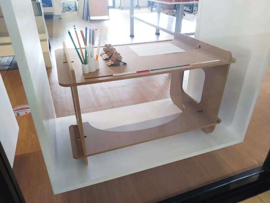
16. The end result was as follows:
17. Some problems I had and how I solved them.
When loading the G code I had some problems since I could not define the origin where I had configured them, the problem was that since fusion the X was the Y of the machine, the solution was very simple (although it took a while to decipher it) The Fusion X must have the same machine coordinate system, the same must be done with Y.
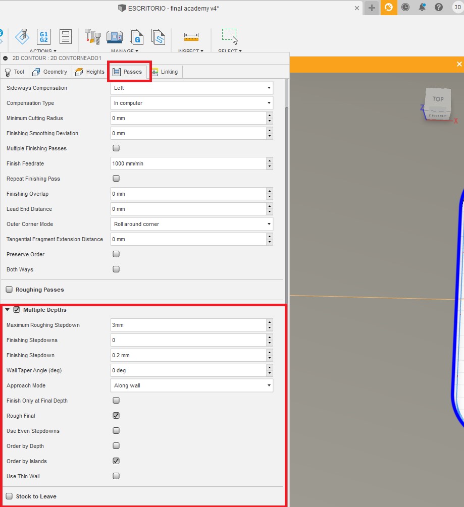
On my first test cut I forgot to set the Z roughing for each pass, by default I set 6mm, which was forcing the tool too much, I paused and set according to the following rule, Roughing = .5X Tool Diameter. So I changed the Z passes to 3mm per pass. This is configured from here:
![]()

You can find all the files of this assignment HERE
![]()
Copyright 2022 Jose Manuel Diaz Bello