
General objective (group assignment)
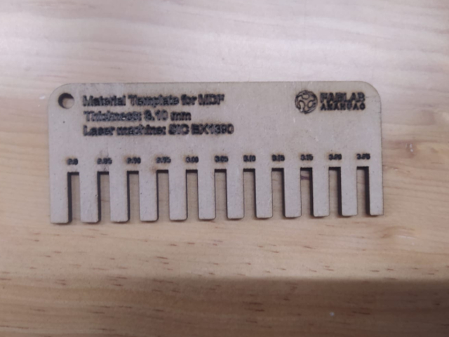
• Characterize your lasercutter's focus, power, speed, rate, kerf, and joint clearance
• Document your work to the group work page and reflect on your individual page what you learned)
Machine used
Technical characteristics
• Work area. 1300 x 900 mm | Height. 35mm
• Type of technology. CO2 laser cutting
• Max and min resolution. 4,000 DPI, 2,000 DPI
• Power, if any necessary. 2.4 kw
• Model. SIC-BX1390
• Mark. SIDECO
In the group assignment I was in charge of characterizing 3mm thick MDF and 4m corrugated cardboard.
The results I got are the following:
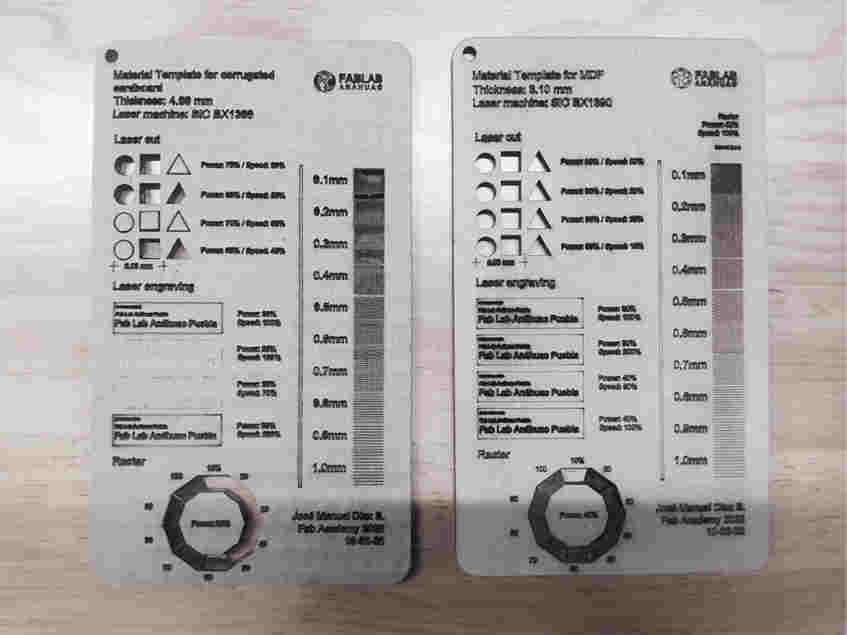
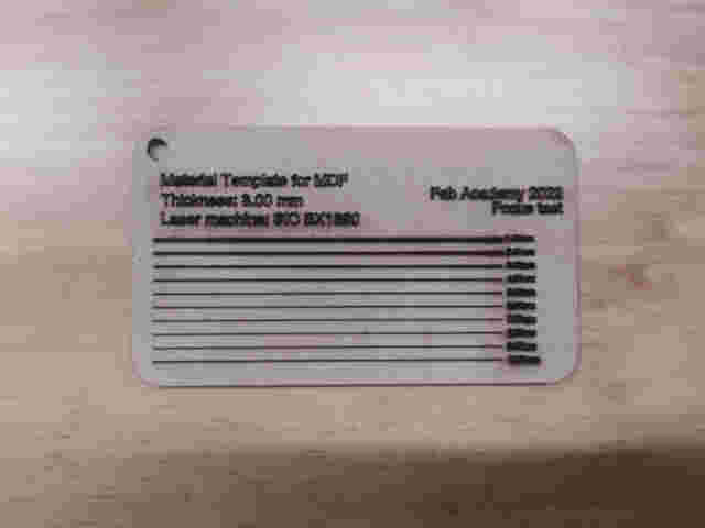
Material. MDF
Thickness. 3.00 mm
Engraving. Power 40% Speed 100m/s
Raster. Power 40% Speed 80m/s Interval 0.2-0.3mm
Laser cut. Power 95% Speed 25m/s
Kerf. 0.175mm
Focus. 7.00mm
Material. Corrugated cardboard
Thickness. 4.00 mm
Engraving. Power 35% Speed 200m/s
Raster. Power 28% Speed 100m/s Interval 0.4-0.7mm
Laser cut. Power 80% Speed 55m/s
Kerf. 0.175mm
Focus. 7.00mm
***************************************
You can check the entire group assignment by clicking here
***************************************
![]()

You can download all the files of this assignment here
![]()
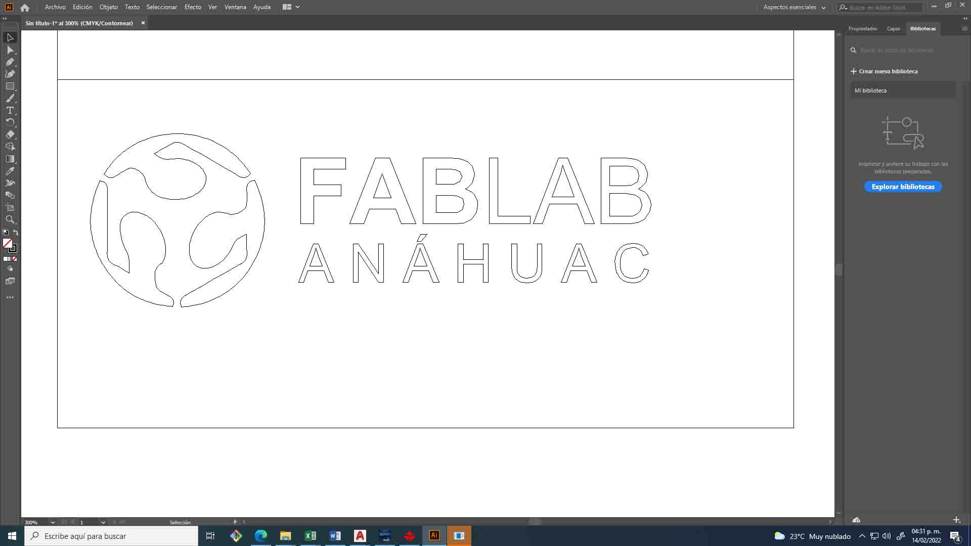
1. For vinyl cutting I will use the fab lab logo to do some experiments.
I've seen some interesting exercises that combine vinyl cutting and sandblasting, we have a machine like that, so I'll do some testing on materials with different textures.
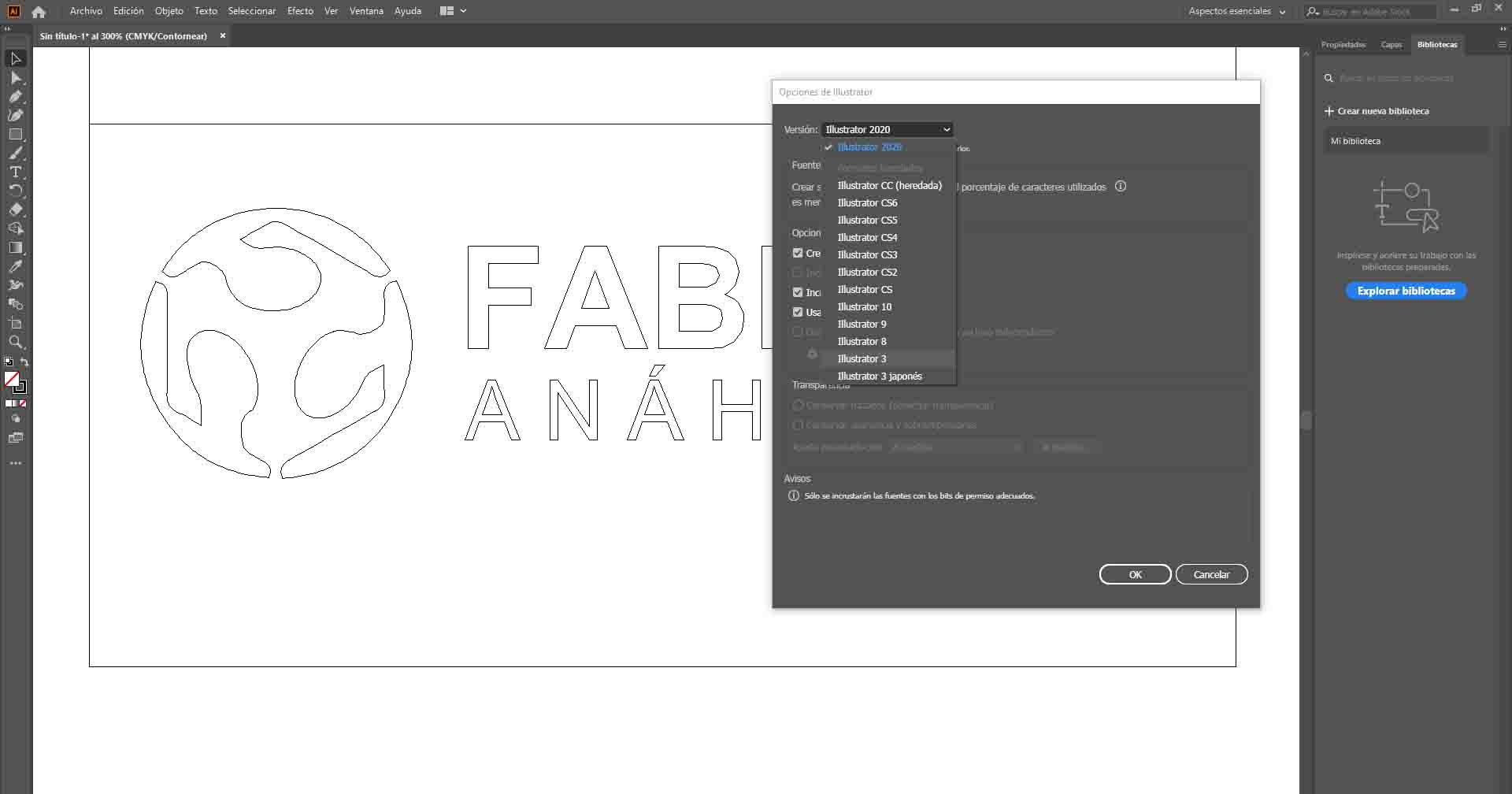
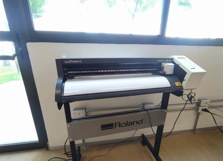
2. Our machine is a Roland Camm-1 GS24, the control software it uses is Cut Studio, this program has a peculiarity, it works with vectors in different formats but if you make your project in Illustrator you must save your file in Illustrator format 3
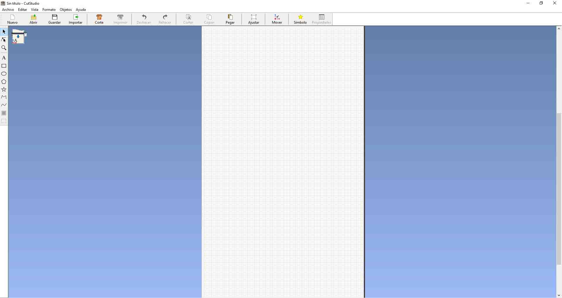
3. Now I turned on the machine and ran the program to start the cutting process.
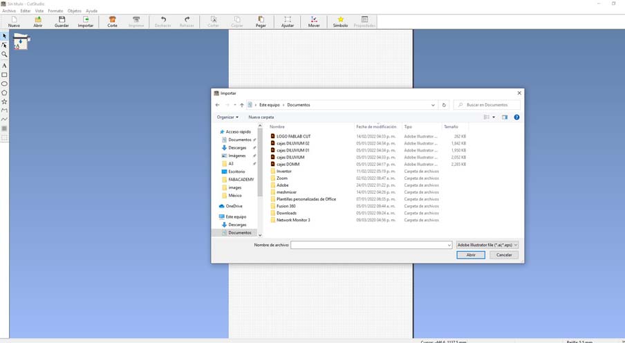
4. I imported the file from the import icon. (The use of this equipment is extremely simple)
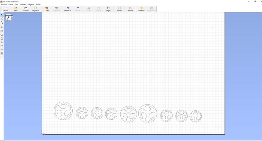
5. Once you click open, you will be able to see your vector at the bottom.
6. The origin of this machine is in the lower left part, we must take this into account so as not to have surprises when cutting.
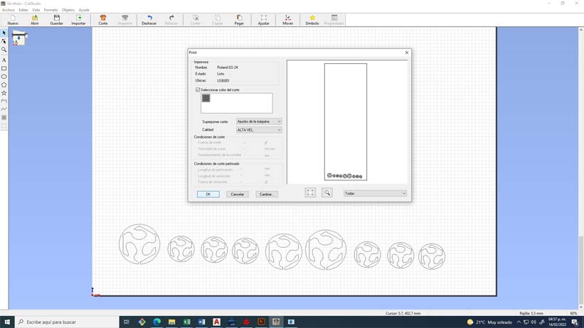
7. We select the color of the layers that we want to cut, we select the quality, in this case I select the high quality option.
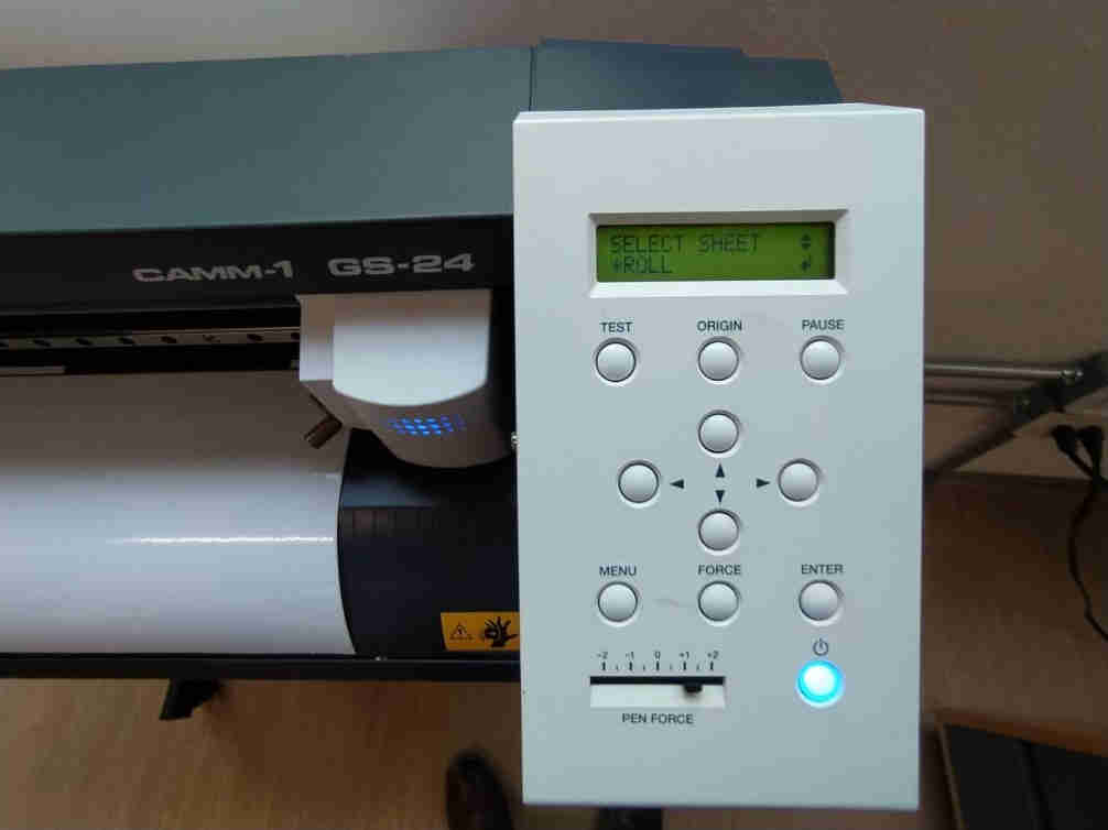
8. When turning on the machine, it will ask us what type of material we are working with, if it is a piece, a sheet or a roll, in this case I select the roll option, also select the pencil +1 force, it is a good force for standard vinyl materials.
***********************************
Cutting speed: 50 mm/s
Cutting force: 350gf (+2)
File format: .AI (version 3)
**********************************
9. Now we do click on cut to start the magic
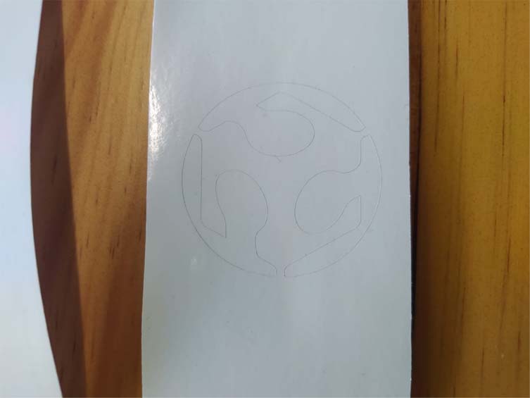
10. Once the cut is finished, we must cut our pieces very carefully, especially when we work with light materials, since sometimes it is difficult to differentiate the cutting lines.
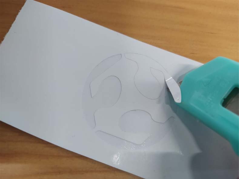
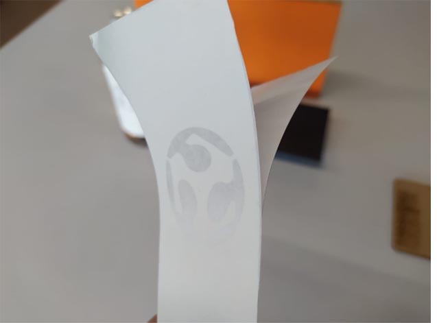
11. For these exercises I will use the negatives of the cut so I will detach the positive pieces.
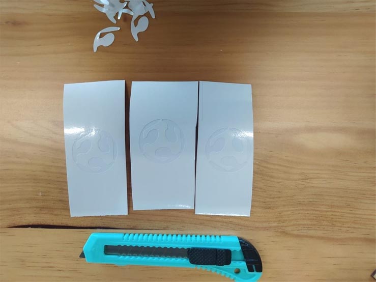
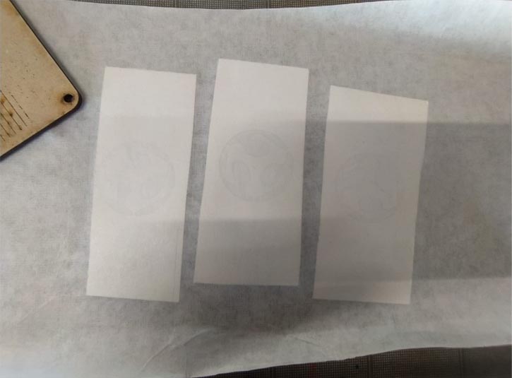
12. Once I have waxed all 3 cuts I will apply the transfer paper. If at any time you do not have this paper, you can use citation masking tape. Now that we apply the transfer paper we must iron the pieces, for this you can use any object that has a totally straight face.
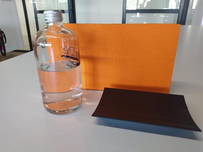
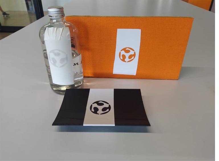
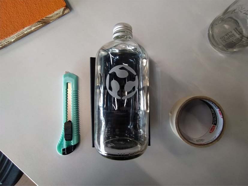
13. These are the objects that I will use for this experiment, I chose them because they will allow me to observe the behavior of this technique on smooth and rough surfaces.
The chosen ones are a glass bottle, a piece printed in PLA and a wooden panel with a rough texture.
14. Peel back the paper from the vinyl and apply to the surfaces, ironing once more on the surface.
15. Application on surfaces.
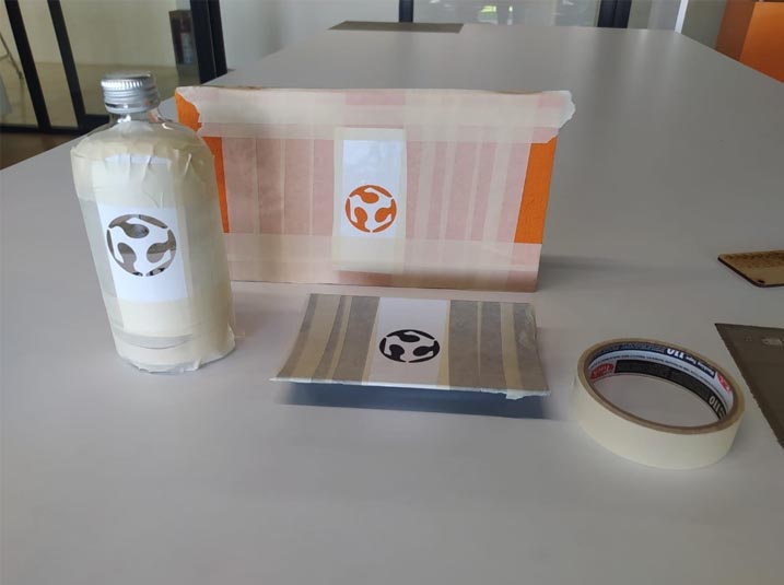
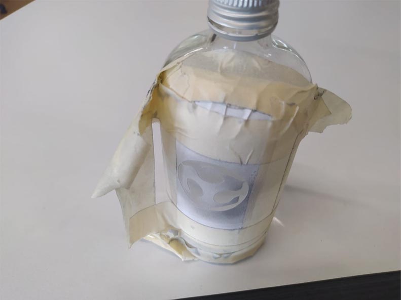
16. Once the stickers have been applied, we must remove the transfer paper and cover the rest of the surface to avoid errors when roughing with sand.
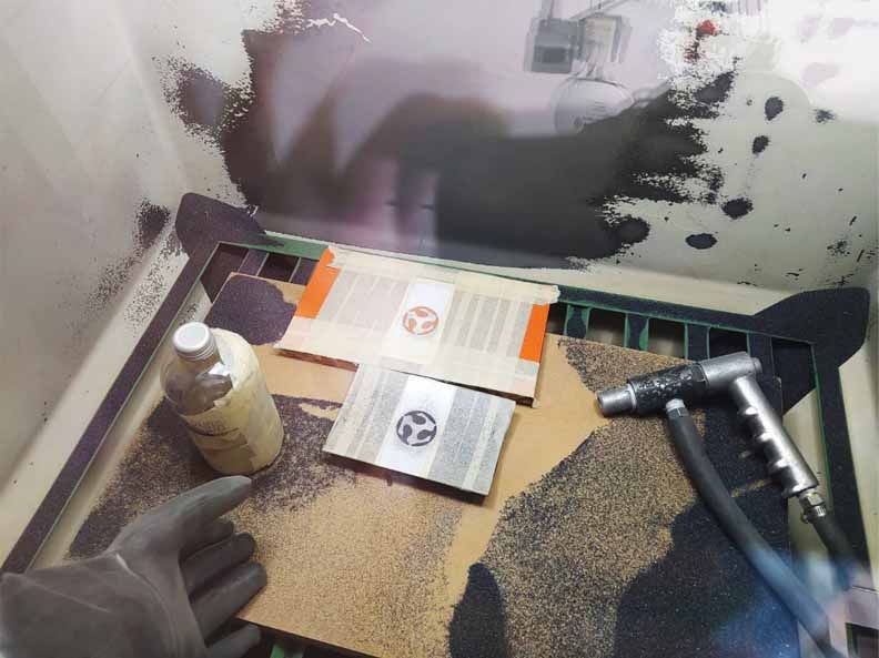
17. Now comes the interesting part. We put our pieces into the sandblasting machine. We turn on the power, air assist, lights and engine.
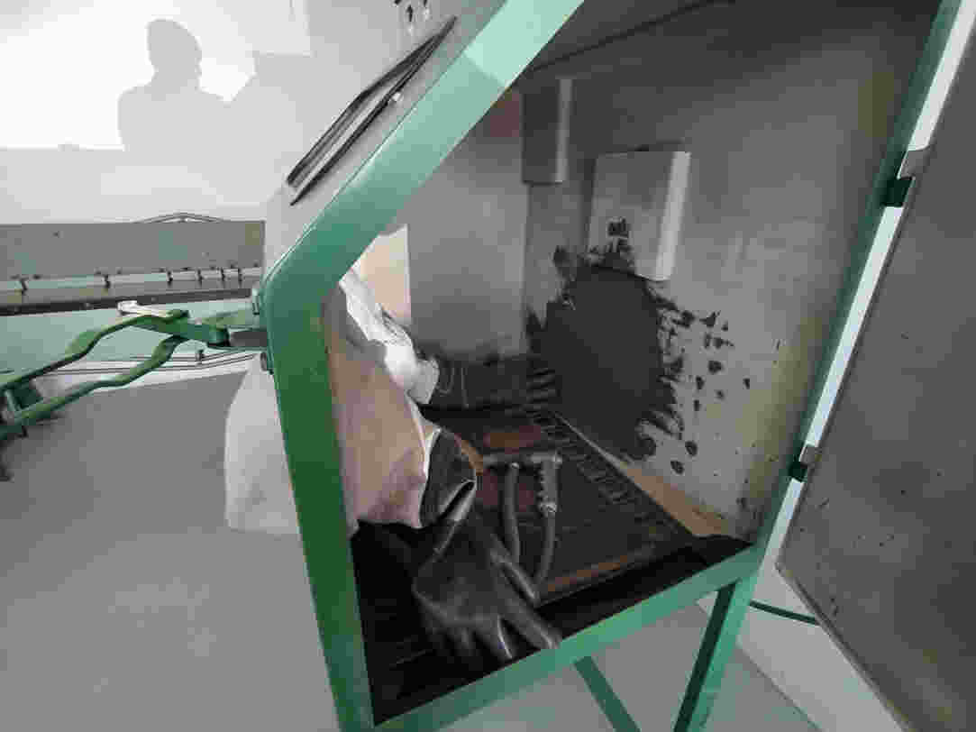
18. This process consists of blowing sand under pressure to devastate certain materials such as glass, cloth, metals and a large number of experimental materials.
19. Lastly, we cleaned up the sand residue and removed the vinyl and duct tape protection.
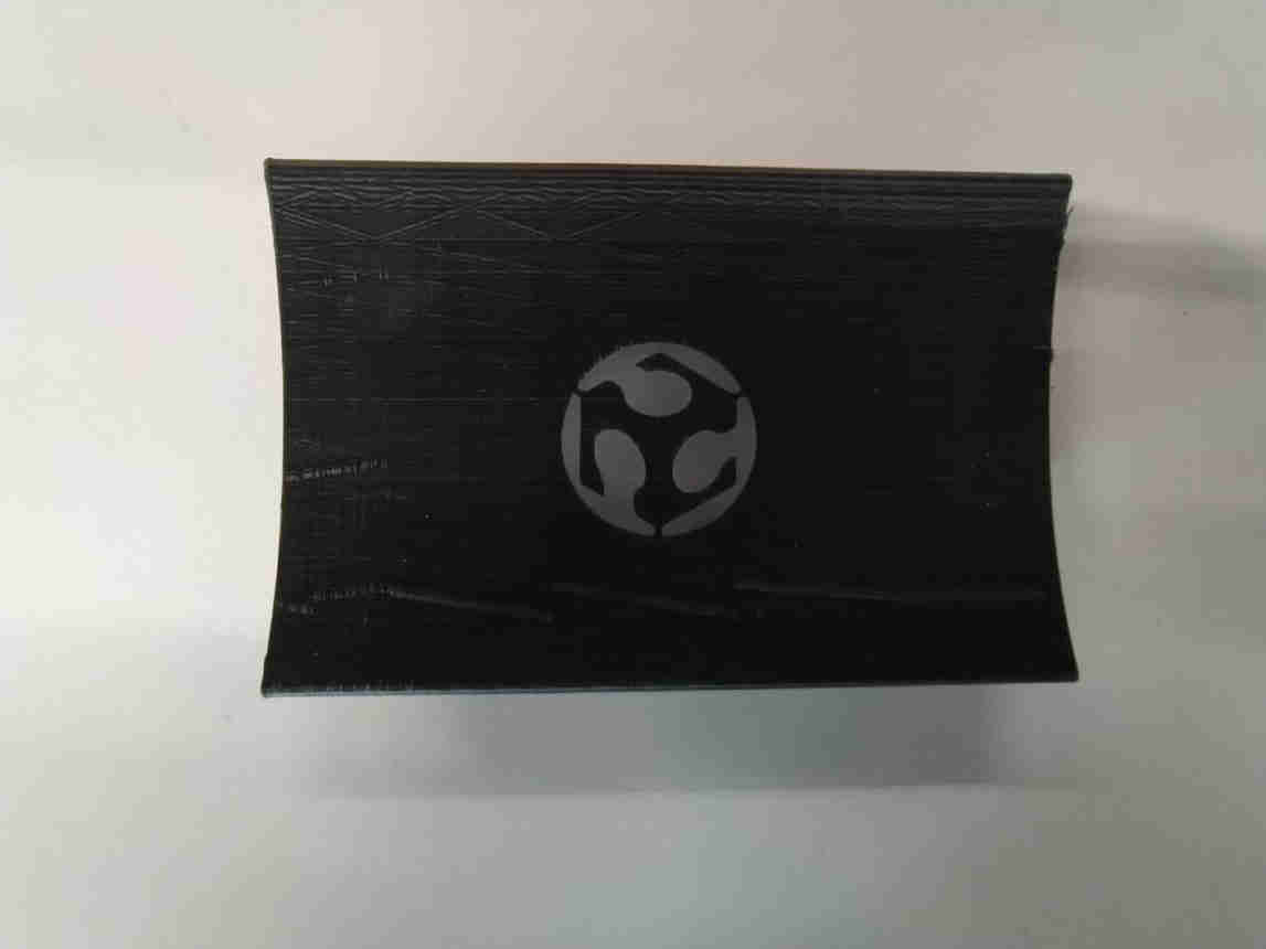
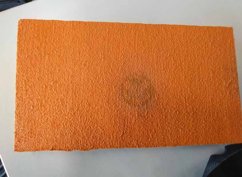
20. Next, the final result.
21. In the printed piece a very interesting result was also obtained, although as expected in the piece with a rough texture the result was quite bad.
__________________________________________________________________________________________________________________________
Take advantage of the fact that I already had the FabLab Anahuac logo vectorized to make some t-shirts with textile vinyl for our team of students.
Use the following parameters:
Temperature 160° 23 seconds
Then fix 160° at 5 seconds.
__________________________________________________________________________________________________________________________
.jpg)
22. Design, cut and document a parametric construction kit.
For this exercise I used Fusion 360 since I have recently experimented with it and it seems like a fairly powerful software with a friendly interface.
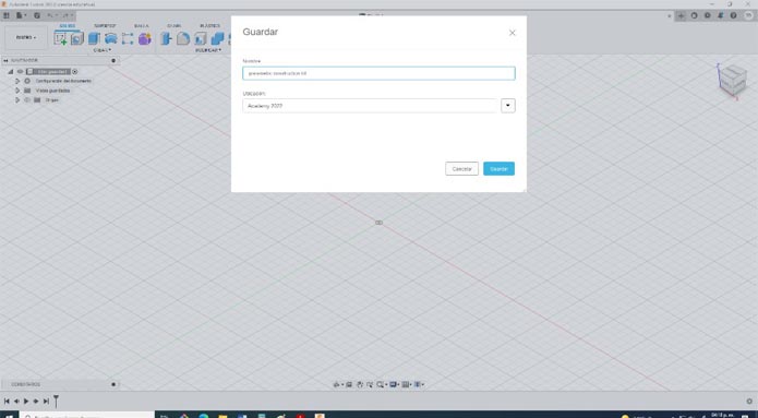
The first thing was to create a new file
______________________________________________________________
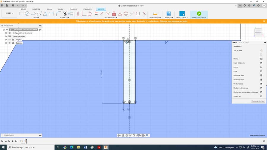
Some preliminary tests for the design of the pressure assembly
______________________________________________________________
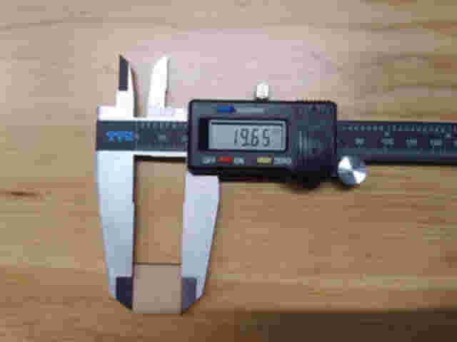
Length on CAD drawing: 20mm
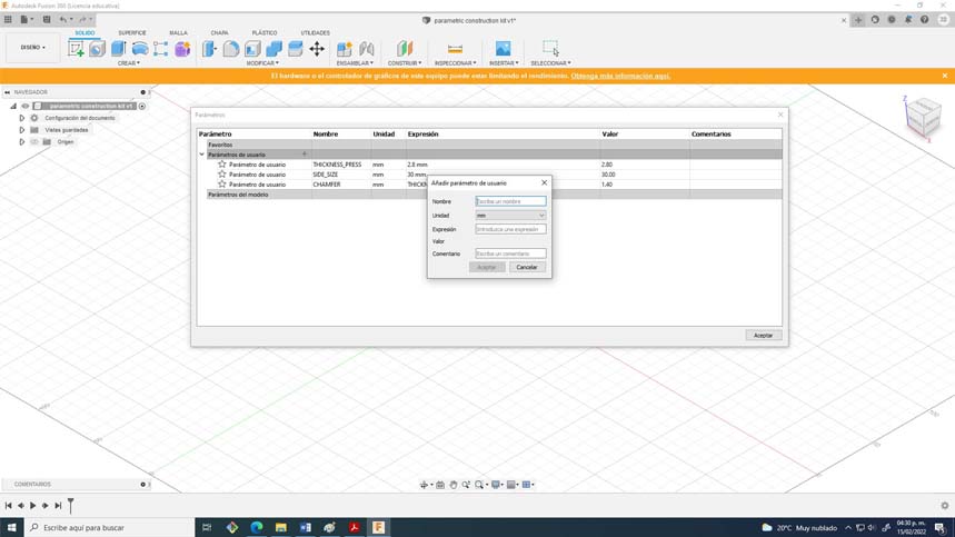
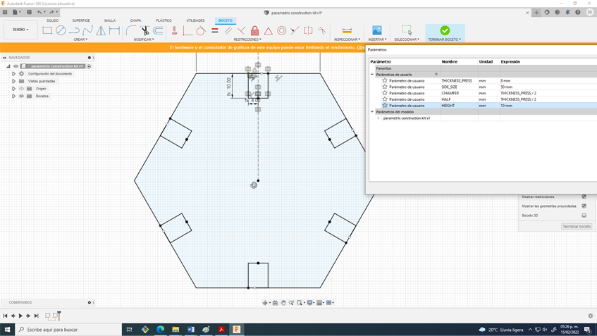
24. Later I started assigning some parameters such as the width of the side, the height of the assembly, the chamfer and the width of the material, discounting the kerf. For this you can use the “S” command and type change parameters, some were units and others were equations.
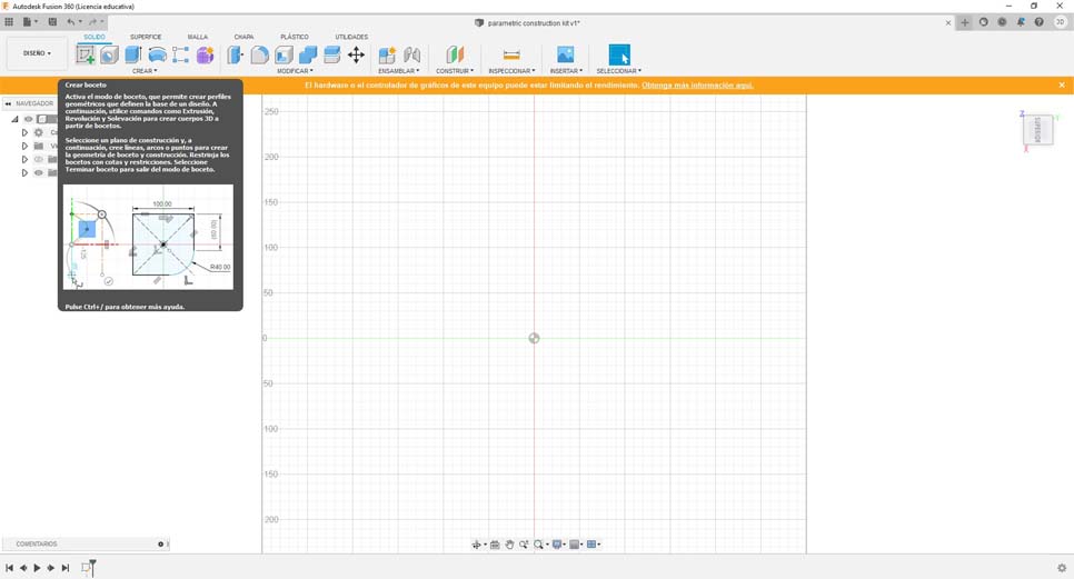
25. Then I created a new sketch and placed it on the bottom plane, blend always works like this, everything you model always starts with a sketch.
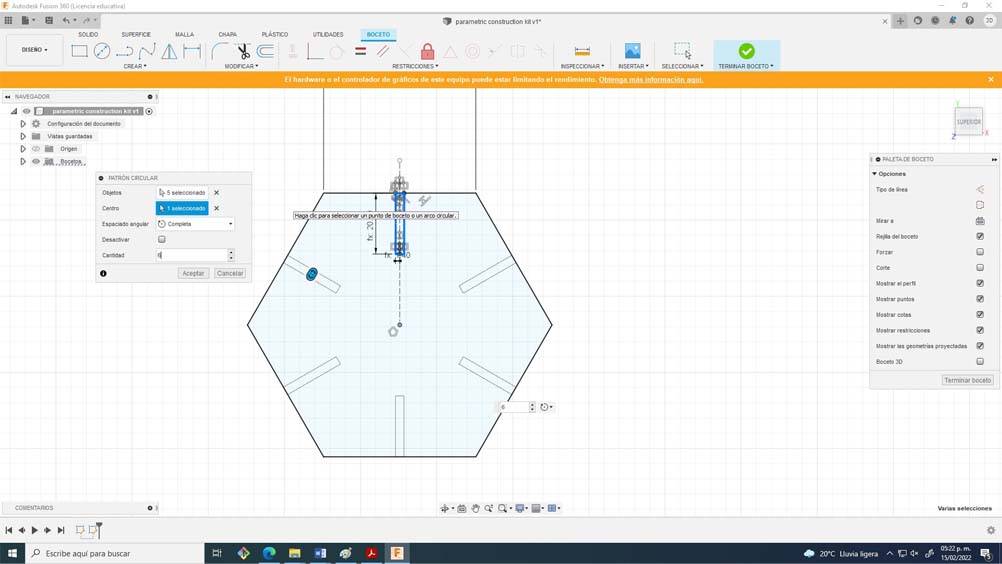
26. I found it interesting to work with a hexagon since it has many geometric possibilities, a very useful advice that I can give you is to only model one half of the assembly, then make a symmetry to that half, and finally create a circular pattern by selecting the number of sides of the polygon. It is important to include constraints such as symmetry, perpendicular, collinear, and tangency.
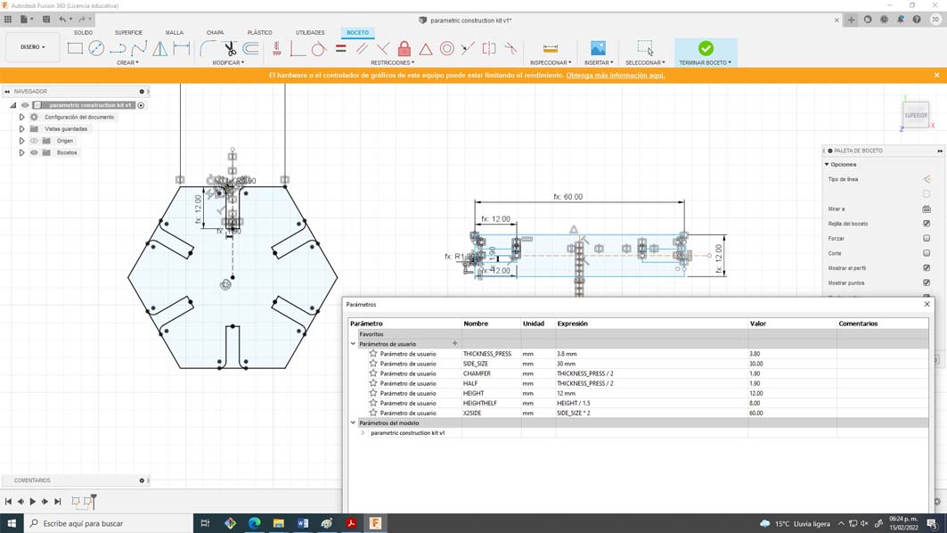
27. If you don't do it that way when changing the parameters you will have some composition problems. The most satisfying thing about this process is changing the parameters and everything works great.
28. To finish I designed connectors so that hexagons can be used as nodes, I used the same parameters with some variations.
29. To finish this process I exported the file in DXF format to process it in RD Works.
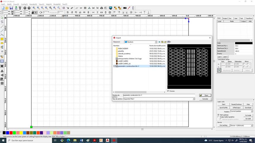
30. Import into RD Works and assign parameters
***********************************
Material. Corrugated cardboard
Thickness. 4.00 mm
Power: 80%
Speed 55m/s
Kerf. 0.175mm
Focus. 7.00mm
***********************************
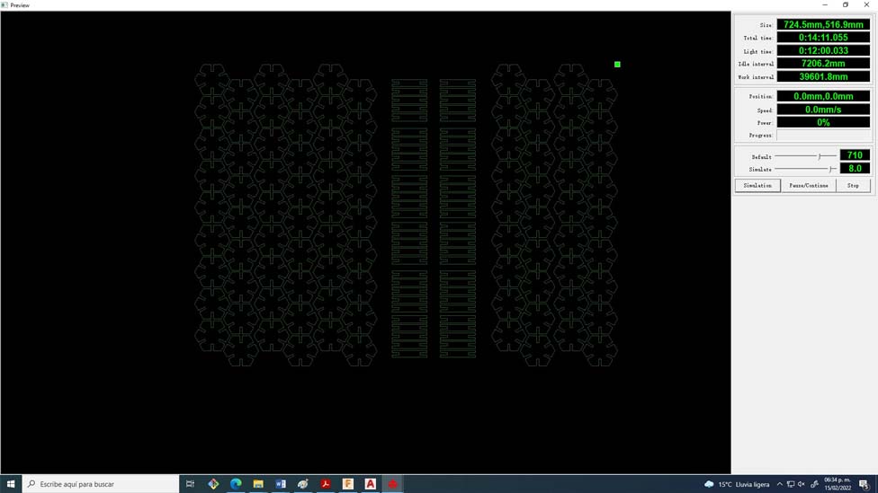
31. Simulated cut time and saved to USB for cut. finally lol
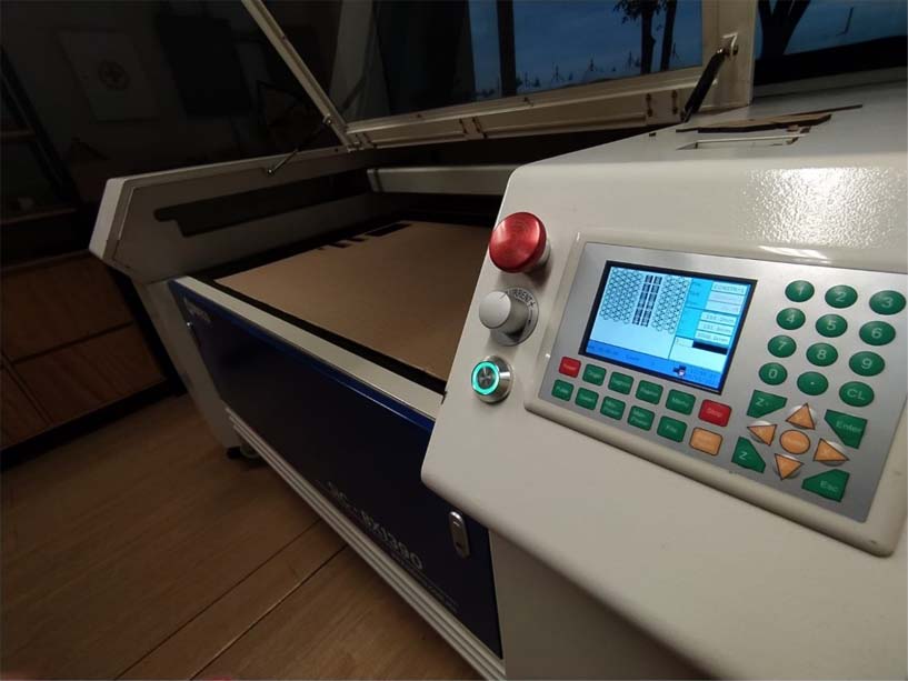
32. We export, we calibrate the height, we turn on air and extracts, finally we click on start.
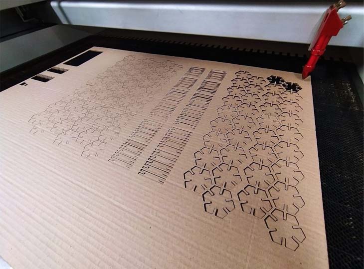
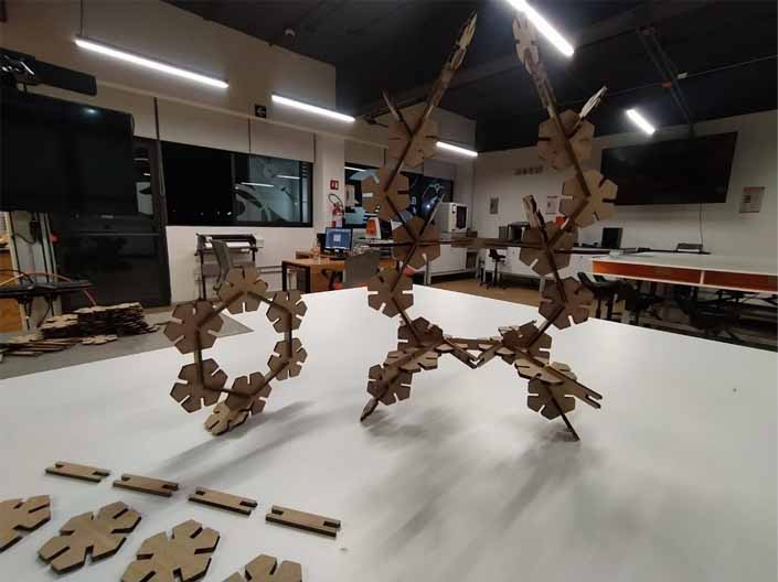
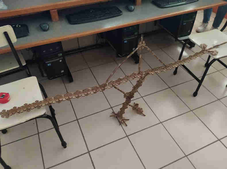
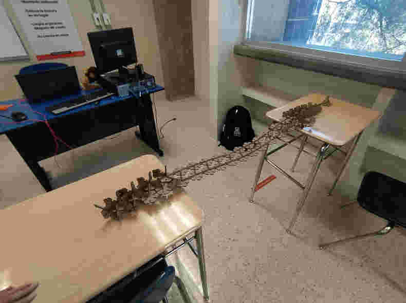
33. After 14 minutes of cutting we have our parametric build kit.
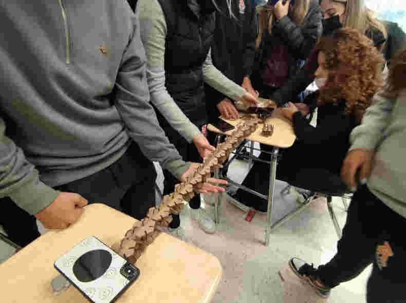
Now it's time to try it out and experiment with some sculptures
_____________________________________________________________________________________
Update 1-03-2022
These days I had the opportunity to lead some workshops for high school students, it was a very good time to talk about digital fabrication and experiment with the construction kit, the results obtained were incredible.
Copyright 2022 Jose Manuel Diaz Bello