
02/03/2022 This week at the conference we got an introduction on different 2D and 3D drawing options. I discovered many interesting programs that I did not know so I will try to experiment with some of them, and for the moment I will leave aside those programs that I have already worked with such as SketchUp , Illustrator and Photoshop. Join me to experiment.
Assignment:
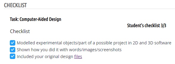
Model (raster, vector, 2D, 3D, render, animate, simulate, ...) a possible final project, compress your images and videos, and post a description with your design files on your class page.
2D drawing.
The 2D drawing can be classified into two large groups, first of all the raster-based, that is, it is a composition of pixels where we can play with color, types of brushes and transparencies, the disadvantage of this category is usually the resolution, since when scaling the drawings we can have some problems, some of the most famous are Photoshop and GIMP, the other group is vector drawing software, basically they are drawings that are created from graphic or programming environments, the strokes are composed by routes and mathematical formulas, this has many advantages, the most interesting is that with these lines we have no loss of resolution when scaling. But less blah blah and more action.
The first software that we will test will be GIMP, with which we will carry out the conceptualization process of the final project
I decided to make an infographic with important data that I have found about Montessori education, sensory levels of furniture and sketches of my final project.
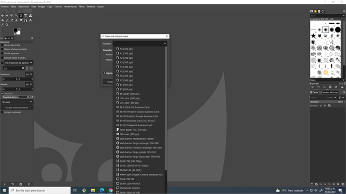
To start your project, the program will allow you to access preset size templates, such as international paper, web sizes and others. You can also create your work canvas by customizing the size in centimeters or pixels.
Before starting, it is always good to review tutorials that guide us on the generalities of the software, these are the ones that I consult:
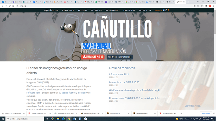
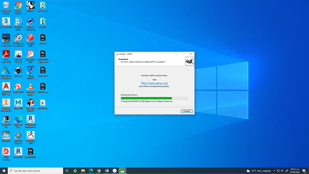
Download the program from the official page
I decided to make a presentation including initial project ideas as well as design concepts and interesting facts.
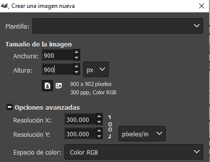
R1. In GIMP the first thing I did was create a workspace of 900 x 900 pixels with a resolution of 300 dpi
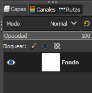
R2. Once created, we must identify the layer window since each element that we embed should be on a separate layer to work more comfortably.
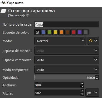
R3. When embedding some elements automatically generate a new layer, but in case this does not happen you can create a new layer by right clicking on the layers window >> New Layer
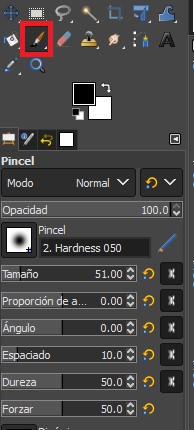
R4. The sketches are made with the help of a WACOM tablet, for this use the brush tool, this can be configured in size, color, opacity, hardness, Angle and spacing.
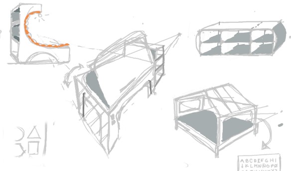
R5. The end result of the first brush sketches.
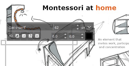
R6. The text tool was also very useful for me to finish conceptualizing my idea. It is convenient to create a new layer so that it is not combined with other elements.
R7. To place new images there are several options that worked for me:
1. CTRL+C from the internet browser and CTRL+V in GIMP
2. Download the image and drag it directly from the file location.
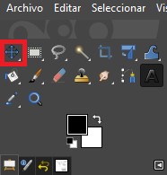
The move tool will help us to move the images within the workspace.
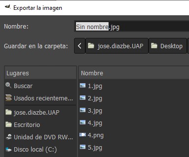
R8. To finish we must export the file in a format compatible with our Web page editing software, in my case JPG.
File >> Export As
R9. My main “problem” with this program was that at first I wasn't creating new layers, so all the elements I placed and created were grouped on the same layer, which makes editing very difficult since it is not possible to edit the elements independently , but once I understood the workflow creating new layers for each element everything worked like a charm.
This process helped me a lot, here I came to the conclusion of making a project that integrates different activities in a single piece of furniture, in this case, studying, recreational reading and storage.
![]()
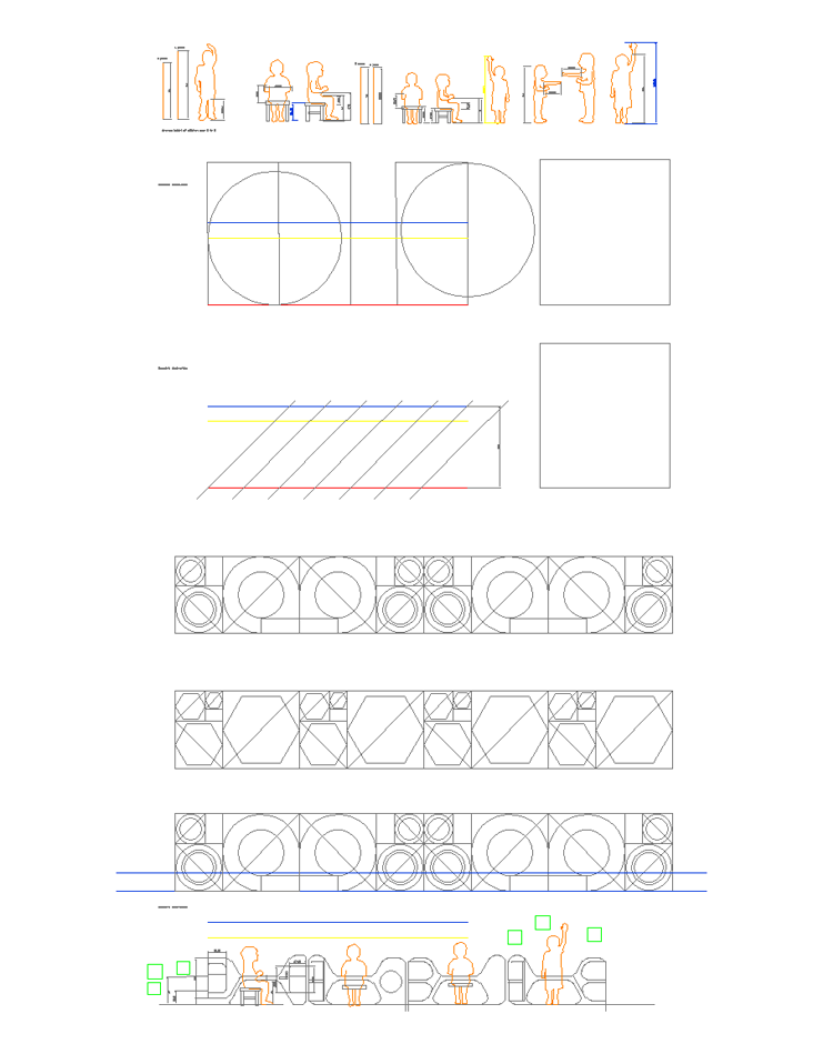
Subsequently, I used the drawing with vectors to carry out a study on the anthropometric measurements of my user, in this case children from 3 to 6 years old.
I also performed a geometric abstraction test, which will be useful to define the geometry of the project.
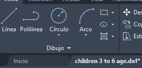
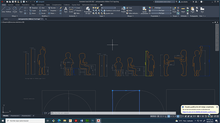
R10. Autocad allows us to work on projects from vector entities, which greatly facilitates the technical drawing of projects.
The first step was to create a new file File >> New >> Drawing
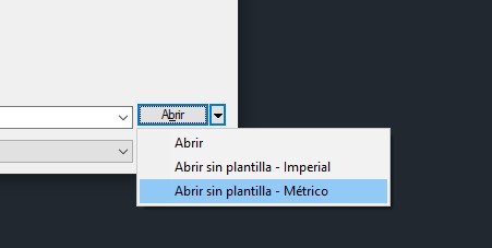
R11. In my case I use a workspace in metric system.
I then researched some anthropometric case studies, which will help me better understand the dimensions of the user I am designing for (3-6 year olds).
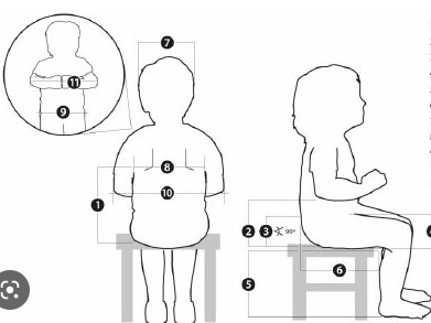
R12. I borrowed some of my nephews to check these measurements on local users. So take the images from the internet as a reference and adjust them with the measurements you develop.
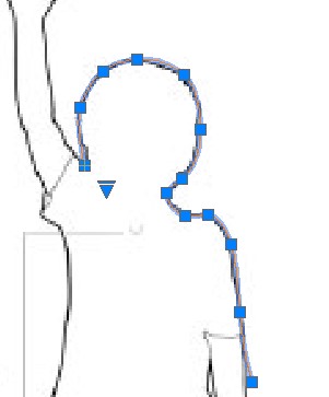
For this I used the SPLINE tool
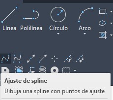
R13. Very easy to use, after a few minutes of practice :D, you just have to position the cursor in key points of the geometry and click, this tool is very useful mainly in curves.
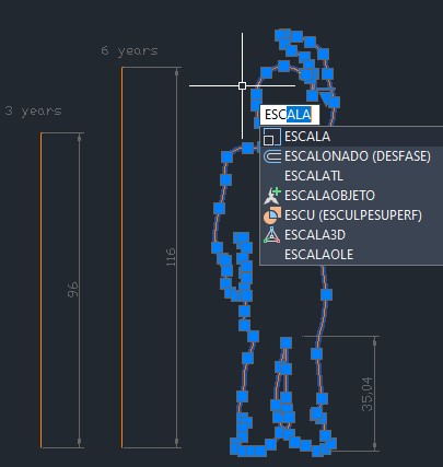
R14. Then I drew reference lines with the measurements I got and scaled my silhouettes.
the process is the following
SCALE >> CHOOSE A BASE POINT >> reference >> Start of reference >> End of reference
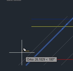
R15. The geometric abstraction process was carried out with polylines, polygons and circles.
R16. In this case I did not use measurements, since this process only helped me to understand what I wanted to achieve morphologically.
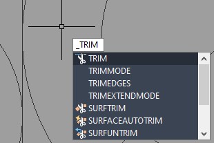
The TRIM tool was very helpful for me to trim from the intersection of elements.
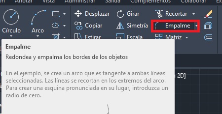
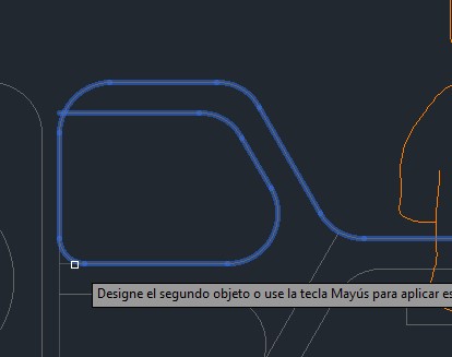
R17. The fillet tool is used to round edges that arise from the intersection of two lines, it is very easy to use: you just have to write the command and select the two lines you want to round, you can choose the radius of the assembly with the letter "R" and indicate with numbers.
R18. Another very useful tool is the offset, it allows you to create equidistant elements from lines already created, the operation process is as follows:
Geometry Selection >> Offset Command >> Enter >> Precise Offset Distance >> Enter Offset Direction.
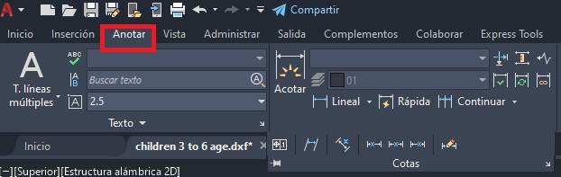
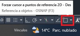
R19. In the "Annotate" menu you will find multiple options to delimit the elements of the drawing, useful to publicize the measures that we are using for the project.
R20. To use this tool it is highly recommended to activate the reference points cursor.
Since we can easily select the reference nodes of each element. (It is located at the bottom right of the interface.
![]()
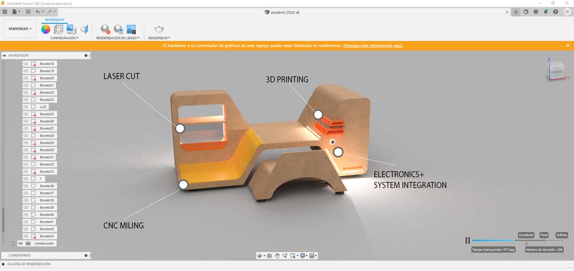
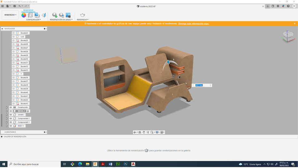
Now that I have defined the dimensions and shapes that we use in the project, it is time to model the first prototype of the final project, for this I used Fusion 360
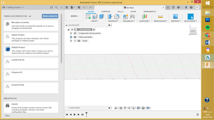
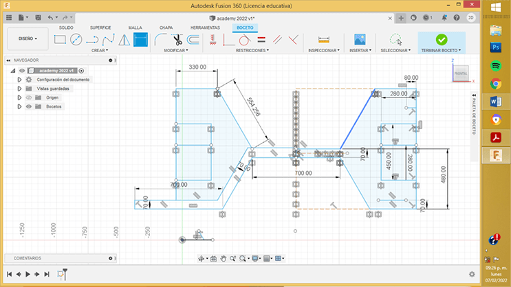
The first step was to create a sketch with the dimensions of the anthropometric study
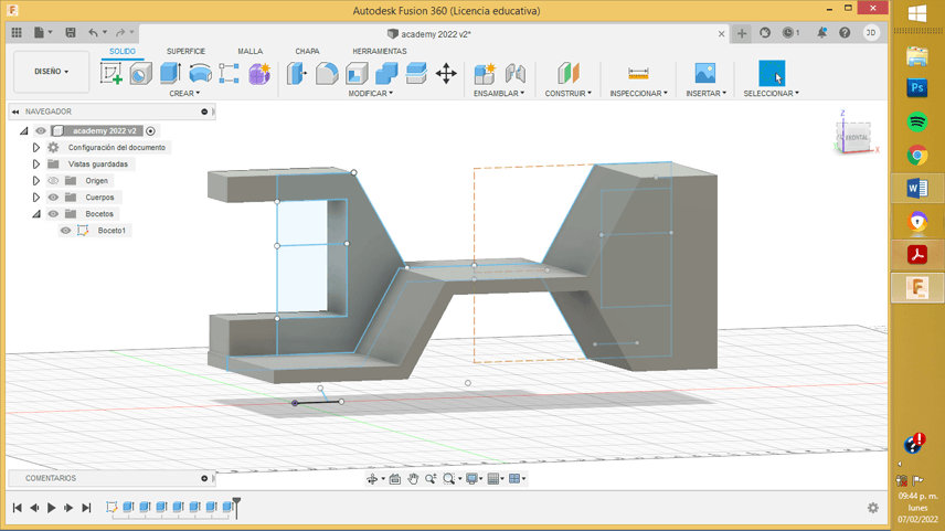
R21. For the creation of this sketch I used one of the most powerful tools of this software, the constraints. These geometric features are automatically created between lines, arcs, and other geometric elements as the sketch is created. Constraints can also be manually applied when the sketch geometry is already created to stabilize the shape or position of the sketch.
The tools I used to create the sketch were the following:
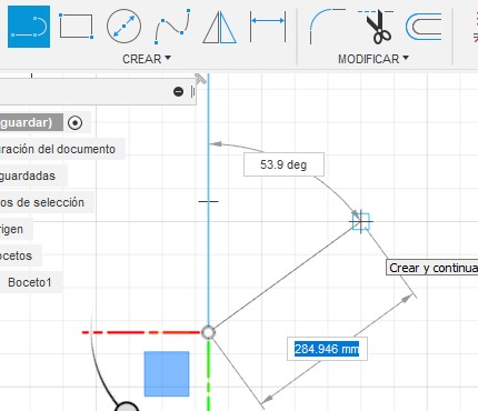
Line allows you to create continuous straight lines, where we can vary the distance and degrees of inclination, to change from one option to another you can use the TAB key
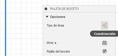
R22. For the project, only draw the left half of the sketch and apply a symmetry reference, for this it is important that we also draw the axis of symmetry, it is highly recommended that we assign the quality construction line.
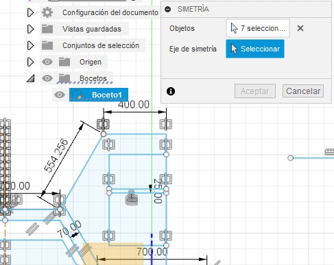
R23. The symmetry is done by selecting the elements that you want to mirror, and then indicating the axis from which the symmetry will unfold.
Once we create the sketch, fusion allows us to extrude the faces to put together the 3D model
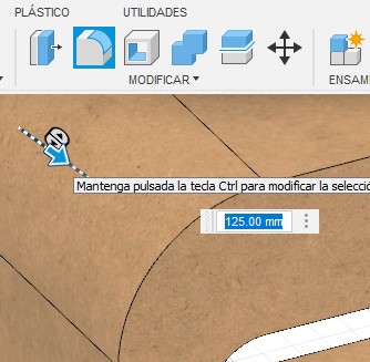
R24. For the rounding of extruded elements I used the splicing tool, its operation is very similar to that of AutoCAD, we only have to indicate the reference radius, it is important to take into account the units that we are using to have an optimal operation.
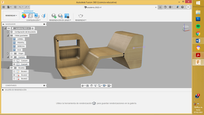
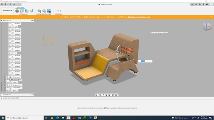
Later, add some geometric details, the retractable table, lighting and materials.
![]()

![]()