Week14- Interface and Application Programming
Introduction
Very very very vast topic, so youtube the tutorials as much as you can.
Assignment
individual assignment:
- write an application that interfaces a user with an input &/or output device that you made
group assignment:
- compare as many tool options as possible
1. Processing + Microcontroller via Serial
This week, Rico took a session for fablab mandela and it really helpful
Processing
- I downloaded processing software from here.
- Processing program (on a PC) is connected to a Microcontroller (MCU)...via Serial Communication
- The connection allows 2-way communication
- Processing sends control signals MCU >> Processing as Input interface (switch, button, etc)
- MCU sends data to Processing for visualization >> Processing as visualization Output (sensor data visualization, etc.)
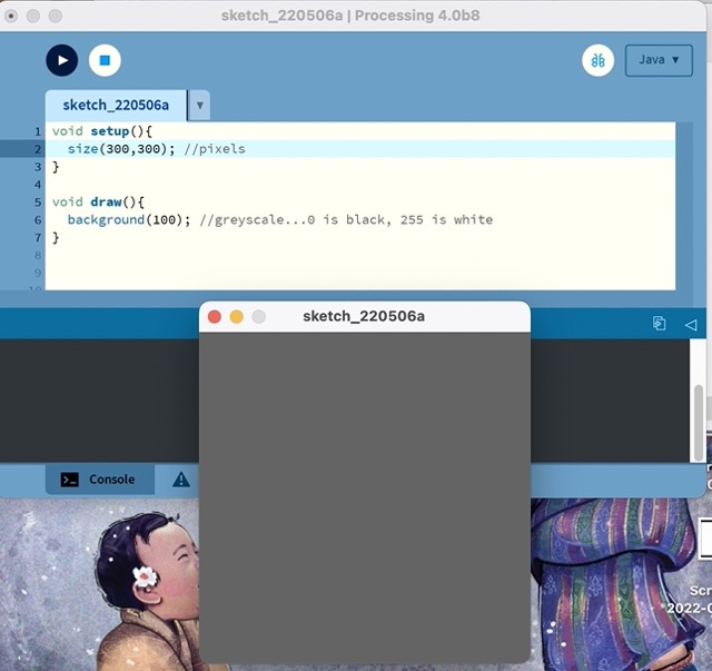
Step 1: Make a Colorful Canvas
- Learning: Working Area (Canvas) sizing, Background color, greyscale, RGB convention
- Let’s make a boring grey, 500px by 500px square canvas >> size(xSize, ySize), background(number)
The colour of the canvas but you can play around the numbers to get different colours.
- Black (0)
- White(255)
- Red (255, 0, 0)
- Green (0, 255, 0)
- Blue (0, 0, 255)
void setup(){
  size(300,300); //pixels
}

void draw(){
  background(100); //greyscale...0 is black, 255 is white
}
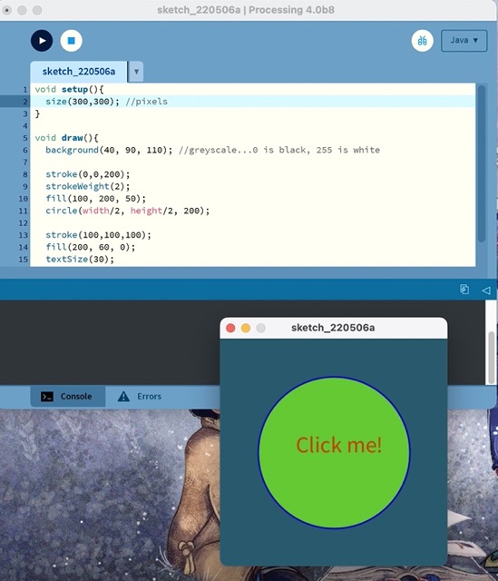
Step 2: Draw Shapes & Text!
Learning: Make ‘2D Primitive’ shapes...rectangle, circle, etc...and text
To make different shapes:
- rectangle- rect
- circle- circle
void setup(){
  size(300,300); //pixels
}

void draw(){
  background(40, 90, 110);
  stroke(0,0,200);
  strokeWeight(2);
  fill(100, 200, 50);
  circle(width/2, height/2, 200);

  stroke(100,100,100);
  fill(200, 60, 0);
  textSize(30);
  text("Click me!", width/2-50, height/2);
}
Step 3: Mouse Events
- Learning: mouse position, mouse click, if-statement
- Make a Pointer: noCursor, mouseX, mouseY
void setup(){
  size(300,300); //pixels
  noCursor();
}

void draw(){
  background(00, 30, 100);

  //Button
  //Conditional statement...button color depends mouse click
  if (mousePressed) {
    fill(90, 20, 10);
  } else {
    fill(255, 0, 255);
  }
  stroke(0,255,255);
  strokeWeight(5);
  circle(width/2, height/2, 200);

  //Pointer
  fill(255,255,0);
  noStroke();
  circle(mouseX, mouseY, 30);
}
Processing > Arduino...the INPUT scenario
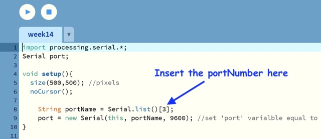
First, we need to import serial library and then specify a variable called port
Processing Button Program
- a button program that send a character through Serial...from Processing program to Arduino program
- import Serial library >> import processing.serial.*;
- create Serial variable >> Serial port;
- initialize Serial object >> port = new Serial(this, portName, 9600);
- generate a Serial write event >> port.write(”k”);
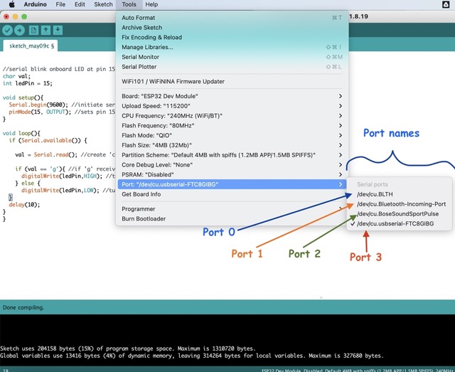
To get the port number, the windows laptop directly give the port number (such as COM4, COM8, COM3) but in Mac, they give the port name. The port I was using to upload programs in the ESP32 board was /dev/cu.usbserial-FTC8IBG. To get the port number which we use in the program to tell the board which port it is using, the numbering is counted as 0,1,2, etc.. Since I am using the port /dev/cu.usbserial-FTC8IBG, the port number is 3.
import processing.serial.*;
Serial port;

void setup(){
  size(500,500); //pixels
  noCursor();

    String portName = Serial.list()[3];
    port = new Serial(this, portName, 9600); //set 'port' varialble equal to new Serial object connected to same COM port as in Arduino at 9600 baud/s
}

void draw(){
  background(100); //greyscale...0 is black, 255 is white

  //Button
  //Conditional statement...button color depends on Pointer position
  if (mouseX > 150 && mouseX < 350 && mouseY > 150 && mouseY < 350 && mousePressed) {
    fill(0, 200, 50);
    port.write('g');
  } else {
    fill(200, 0, 0);
    port.write('0');
  }
  stroke(0,0,200);
  strokeWeight(5);
  circle(width/2, height/2, 200);

  //Pointer
  fill(200,100,0);
  noStroke();
  circle(mouseX, mouseY, 30);
}
Arduino Program
- Arduino program that receives characters from the Processing program via Serial communication connection and triggers actions through MCU pins
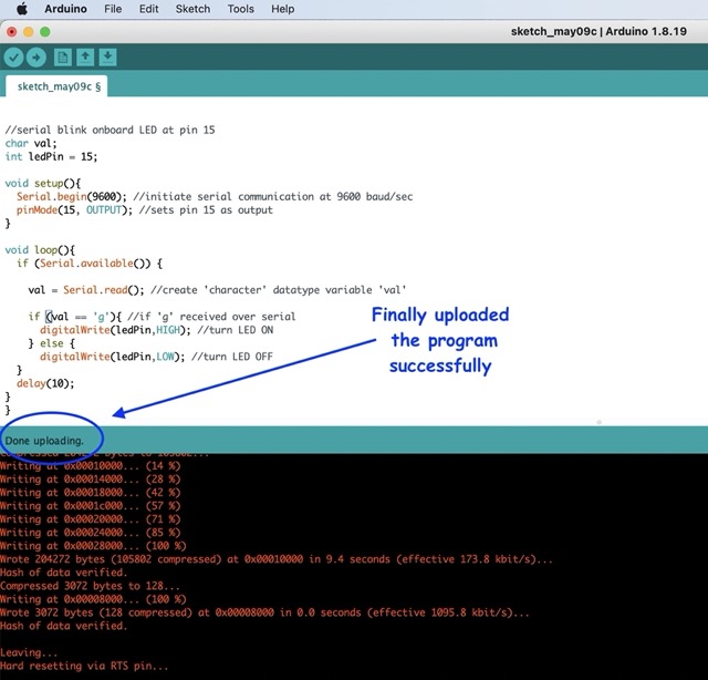
//serial blink onboard LED at pin 15
char val;
int ledPin = 15;

void setup(){
  Serial.begin(9600); //initiate serial communication at 9600 baud/sec
  pinMode(15, OUTPUT); //sets pin 15 as output
}

void loop(){
  if (Serial.available()) {

    val = Serial.read(); //create 'character' datatype variable 'val'

    if (val == 'g'){ //if 'g' received over serial
      digitalWrite(ledPin,HIGH); //turn LED ON
    } else {
      digitalWrite(ledPin,LOW); //turn LED OFF
  }
  delay(10);
}
}
I kept facing the same error for few weeks now but could not debug. Sometimes I could program my board while sometimes I could not. This week, I could finally program my board whenever I hit the upload button on Arduino IDE instead of relying on my luck to program the board successfully
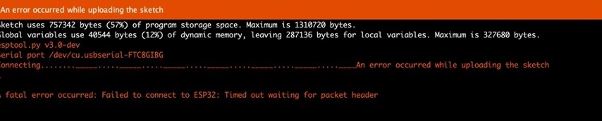
Very very very important points:
No matter how well ur program is, if you cannot upload in your board, then its of no use.
So, note the following points while uploading.

1. Make sure when you upload the program in your board using Arduino IDE the processing is not running.
2. To upload the program, keep the switch button in program and switch it to run while running the program.
3. If your microcontroller is ESP32, make sure to press the reset button before programming the board
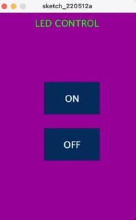
To turn on and off using 2 buttons
I referred this document and youtube tutorial which gives step by step procedure.
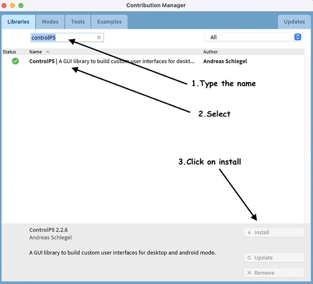
Adding GUI library (ControlP5) to processing
-
Click on sketch-> import library-> add library. controlP5 is a library written by Andreas Schlegel for the programming environment Processing.
-
The processing code
import controlP5.*; //import ControlP5 library
import processing.serial.*;

Serial port;

ControlP5 cp5; //create ControlP5 object
PFont font;

void setup(){ //same as arduino program

  size(300, 450);    //window size, (width, height)

  printArray(Serial.list());   //prints all available serial ports

  port = new Serial(this, "/dev/cu.usbserial-A50285BI", 9600);  // /dev/cu.usbserial-A50285BI is the name of the port in macOS

  //lets add buton to empty window

  cp5 = new ControlP5(this);
  font = createFont("calibri light bold", 20);    // custom fonts for buttons and title

  cp5.addButton("ON")     //"on" is the name of button
    .setPosition(100, 150)  //x and y coordinates of upper left corner of button
    .setSize(120, 70)      //(width, height)
    .setFont(font)
  ;

  cp5.addButton("OFF")     //"off" is the name of button
    .setPosition(100, 250)  //x and y coordinates of upper left corner of button
    .setSize(120, 70)      //(width, height)
    .setFont(font)
  ;

}

void draw(){  //same as loop in arduino

  background(150, 0 , 150); // background color of window (r, g, b) or (0 to 255)

  //lets give title to our window
  fill(0, 255, 0);               //text color (r, g, b)
  textFont(font);
  text("LED CONTROL", 80, 30);  // ("text", x coordinate, y coordinat)
}

//lets add some functions to our buttons
//so whe you press any button, it sends perticular char over serial port


void ON(){
  port.write('a');
}

void OFF(){
  port.write('z');
}
- The arduino code and upload the program.
void setup() {

  pinMode(15, OUTPUT);   //set pin as output , led

  Serial.begin(9600);    //start serial communication @9600 bps
  }

void loop(){

  if(Serial.available()){  //id data is available to read

    char val = Serial.read();

    if(val == 'a'){       //if a received
      digitalWrite(15, HIGH); //turn on led
      }
    if(val == 'z'){       //if z received
      digitalWrite(15, LOW); //turn off led
      }
    }
  }
- The result
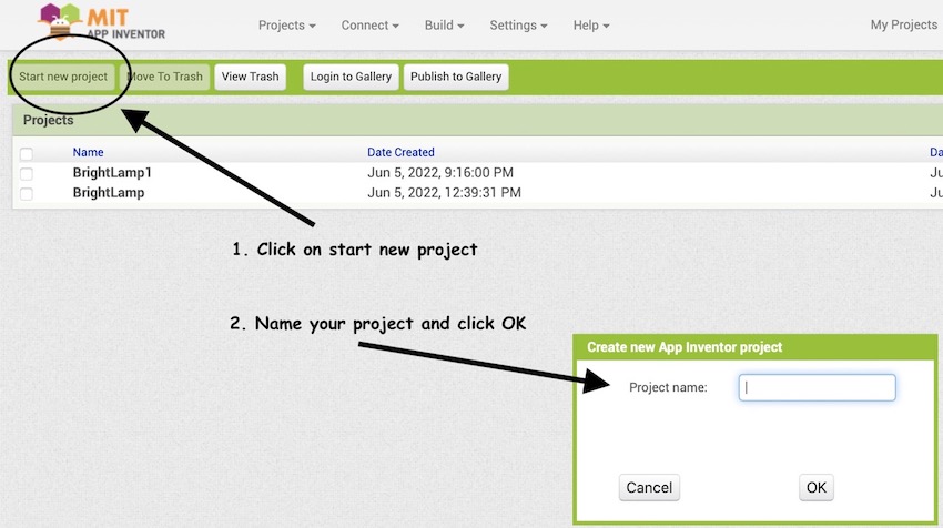
2. MIT app inventor
- I used the MIT app inventor to develop an app for the final project and its quite easy.
-
Click on start new project and name your project
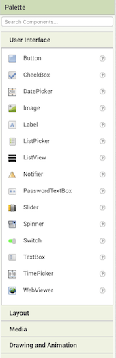
-
On the left hand side, you get the options to choose what you want in the app
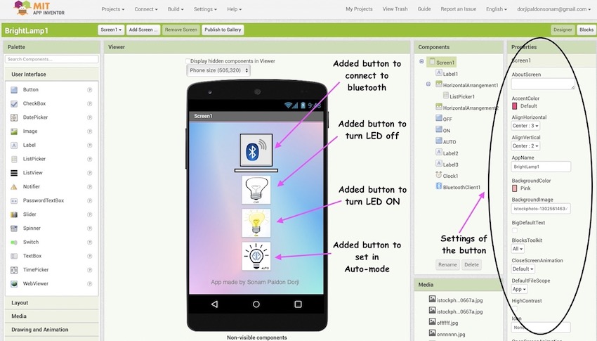
-
Added buttons and inserted image to the buttons
-
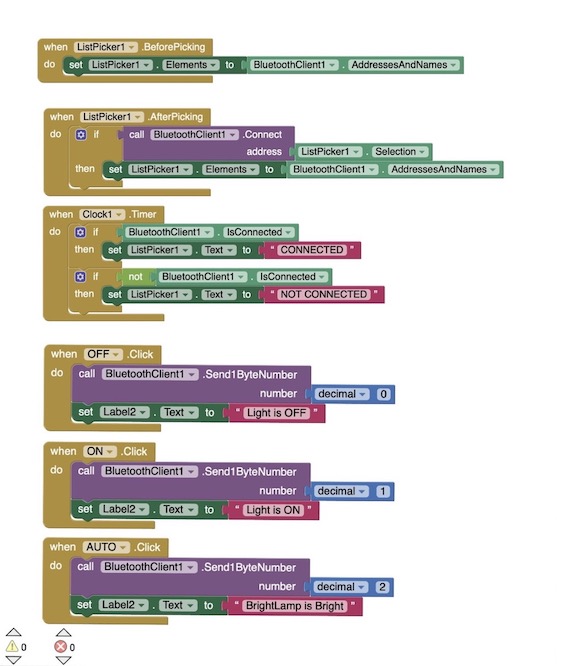
Click on buttons and give the conditions and results
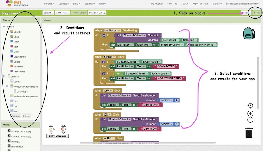
- The conditions and result for bright bright lamp
-
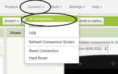
MIT app inventor can be connected to andriod phones only. To use the app in your phone, download the MIT app inventor app in your phone. From the Mac, click on connect-> AI companion and connect to the phone using the QR code that is generated from there.
The file for the app developed using MIT app inventor is here