Task to be carried out this week
Action Plan
| Date | Work Allocation |
| 23rd Feburary | Prof. Neil's Lecture and second review with Prof. Neil. |
| 24th February | Learning about additive and subtractive manufacturing. Lecture on 3D printing technology by local instructor |
| 25th February | Learning more about additive manufacturing |
| 26th February | Designing my 3D model in fusion 360 |
| 27th February | Designing my 3D model |
| 28st February | 3D printing |
| 1st March | Documentation |
Additive and Subtractive Manufacturing
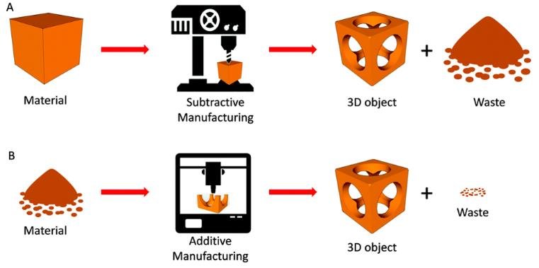
Difference between Additive and Substractive Manufacturing
| Additive Manufacturing | Subtractive Manufacturing |
| Layers of material are added one over another to build 3-D component. | layers of material are removed from a solid block to obtain desired 3-D component. |
| suitable for materials having low melting point. | Melting point usually does not pose any restriction on it. |
| Volumetric density of the working material can be altered during operation | Volumetric density of the working material cannot be altered during operation. |
| No or very less material wastage takes place. | Material wastage occurs in various forms like chips, vaporization, etc. |
| Suitable for a narrow range of materials. | pose no restriction on working material. |
| Suitable for small size components. It cannot accommodate large components. | It can process small to large objects. |
| Any complex shape can be directly produced by these processes. | Component complexity imposes restriction on its feasibility. |
| Fully enclosed internal hollow parts can be fabricated easily. | Fully enclosed cavity cannot be produced. |
| Additive processes are time consuming and require sophisticated equipment, experienced worker and tight environment control. | Subtractive processes are time efficient, economically cheaper and ergonomically relaxing. |
Source: http://www.differencebox.com/engineering/difference-between-additive-and-subtractive-manufacturing/
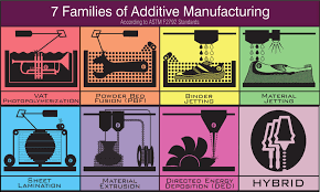
Types of 3D printing or additive maufacturing methods.3D printing is a method of creating a three dimensional object layer-by-layer using a computer created design. 3D printing is an additive process whereby layers of material are built up to create a 3D part thus it is also known as additive manufacturing.
3D model design
The assignment for the week was to design a 3D model that acannot be manufactured subtractively. For that, I had to first understand what was subtractive and what was additivie manufacturing.
When learning about the two 3D object manufacturing methods, I learned that subtractive methods are faster and are more used industrially. However, a lot of matherials are wasted in this method
and there are some shortcomings when it come to the designs that can be manufactured using the method. On the other hand, the additive methods take longer manufacturing time but produces less waste and
can be used to print complicated designs.
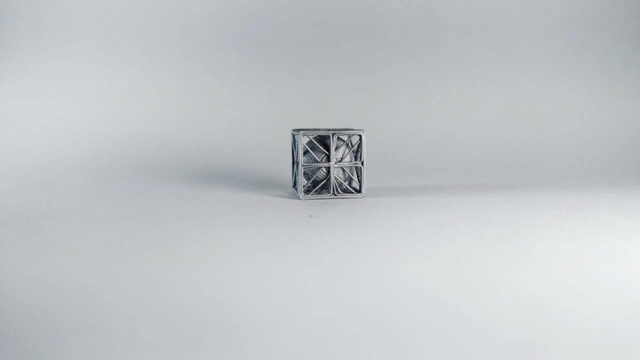
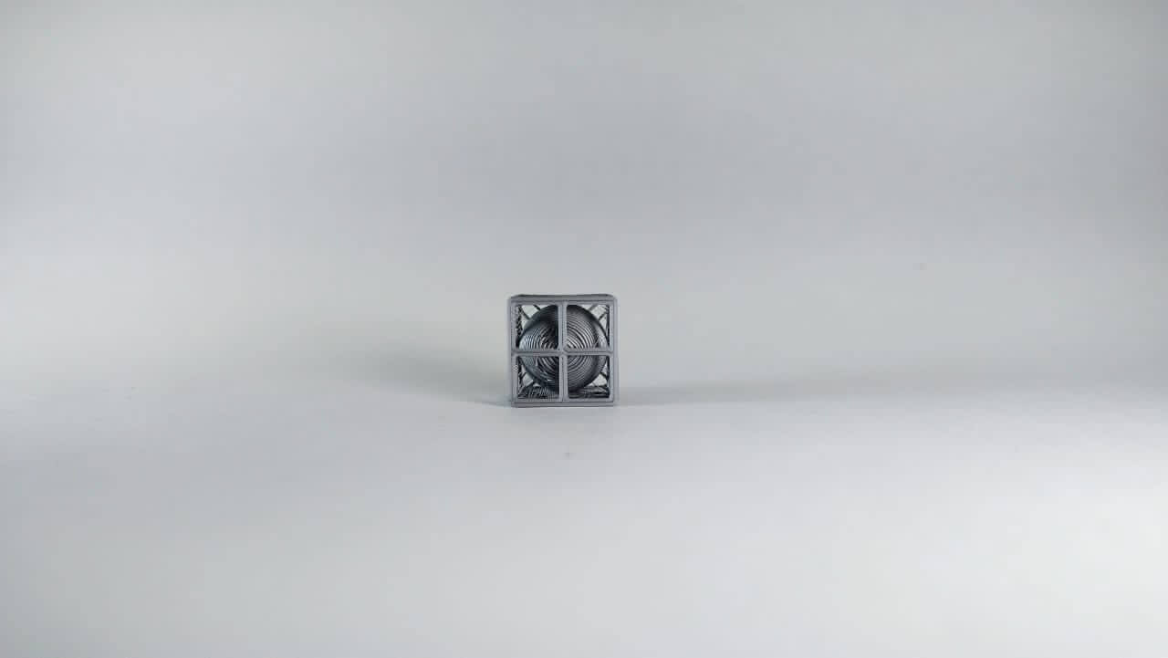
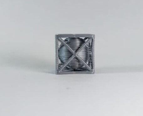
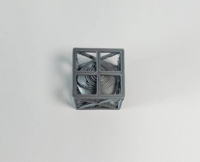
I designed my 3D model in fusion 360. Basically, my idea for the model was to create a sphere enclosed inside a cube-like outer structure. Since 3D printing takes a lot of time, I made my 3D model with small dimension.(15mm*15mm*15mm)
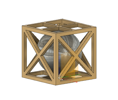
Once I was done with the design, I save the .stl file. The .stl file was then fed into the 3D printer using the Pursaslicer software.
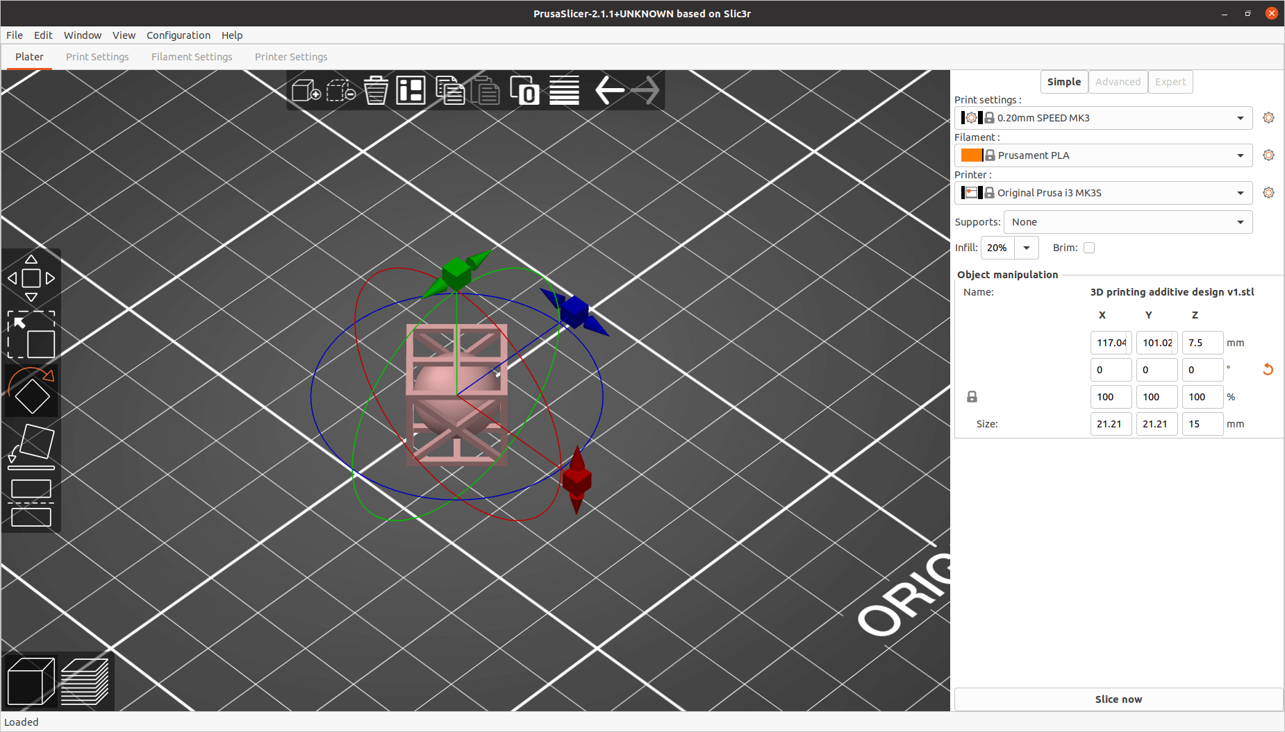
When printing, the following settings need to be made;
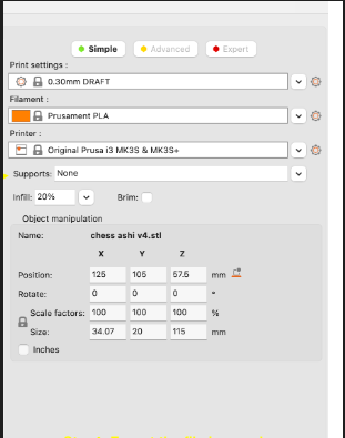
This was the final object printed for the design I made.
3D Scanning
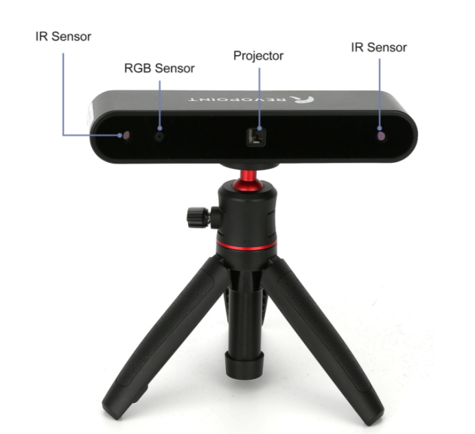
Rovopoint POP 3D Scanner
The Revopoint POP 3D Scanner uses a custom, built-in Binocular Structured Light processor, ensuring highly accurate acquasition of 3D point cloud data.
It has a set of depth cameras(two IR sensors) and one projector using which the POP scanner can obtain a single frame accuracy as high as 0.3mm. It has powerful capabilities that allow a variety of applications
such as scanning model, scluptures, human faces, industrial parts and more. The Revopoint POP 3D scanner is a full-color scanner with unlimited scanning capabilities.
It provides precise and high resolution imaging that accurately captures color and intricate textures for the 3D model. The scanner weighs only about 200grams and has a compact size which makes it
portable. It is compatable with a range of OS including windows, Mac, Android and iOS.
We use the Revo Scan software to view and edit the scan made using Revopoint POP 3D Scanner.
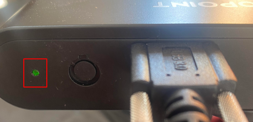
To begin with the scanning process, connect the Revopoint scanner to a USB 3.0+ data port. USB 2.0 doesn't provide sufficient current which will cause the scanner to enter constant disconnect and reboot cycle.
Once the scanner is connected, the LED on the rear of the scanner will start as green, then briefly turn red, then blue. When the indicator turns to green once again from blue, the scanner is ready to use.
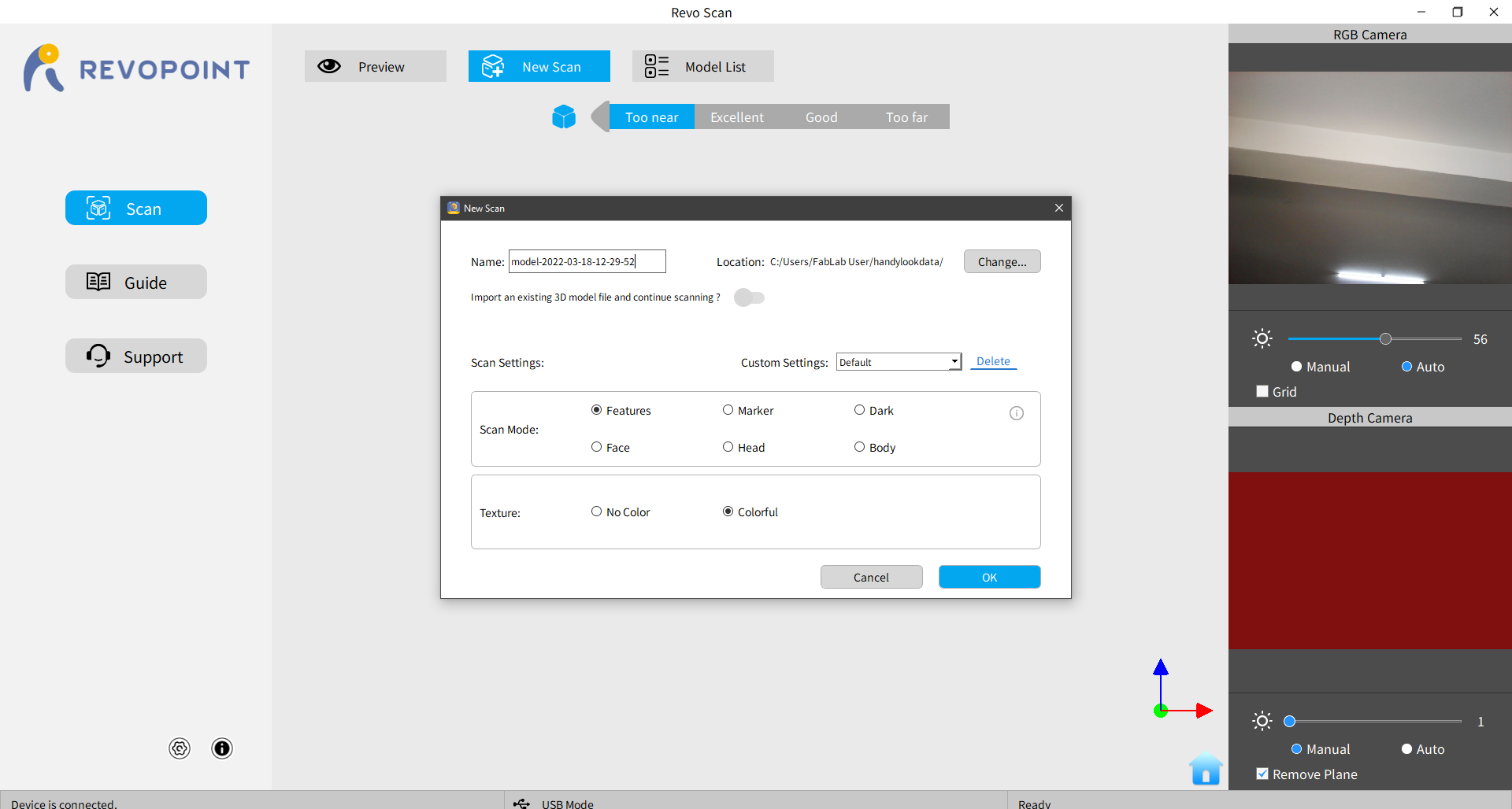
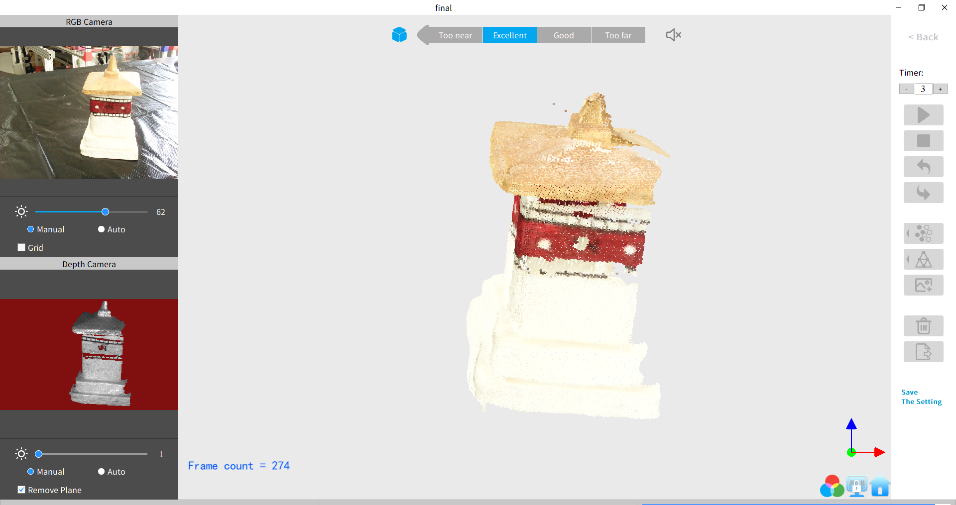
Open the RevoScan software on the PC. Place the object to be scanned and adjust to fit it in the scanning frame. Click on new scan option → change the settings as required(name, location for saved file, scan mode, texture. etc., )
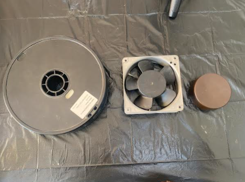
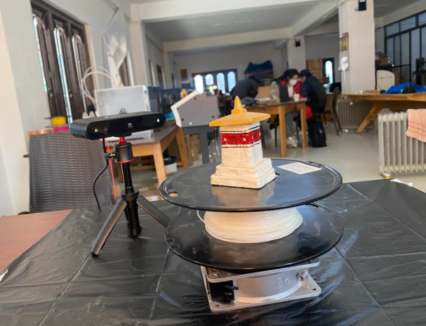
Next rotate the object to get around scan or move the scanner around the object. We made a make-shift rotating table using fan, jar cap and 3D filament roll.
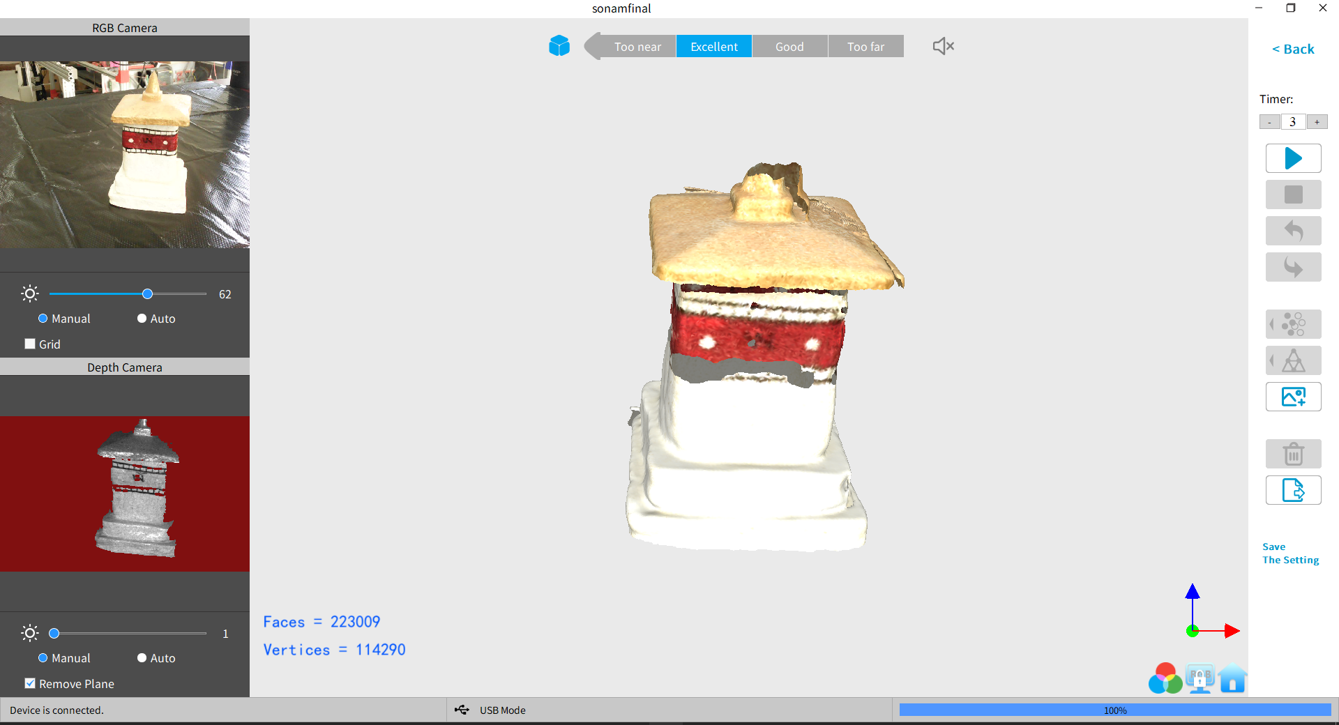
Once the scanning is complete, click on the stop button and apply mesh.
Group Assignment
The 3D printer in our lab is Makerbot Sketch. We have used the makerbot website to learn about the basic working of the makerbot 3D printer and softwares used to 3D Print anything. The details of our reference is available at: https://www.makerbot.com/learn/ and have used the abstract from the site to explain about the printer. The Makerbot Sketch has the following characteristics:
MakerBot's 3D Printers rely on a technology called Fused Deposition Modeling or FDM. It uses an extruder, which acts similar to a hot glue gun. Plastic filament is fed in through the top, is melted at 215 degree,
and finally is 'extruded' out of a small nozzle into the layers that build a 3D print.
Makerbot image Makerbot extruder -image Makerbot filament image
MakerBot 3D Printers know where to move using a three dimensional cartesian coordinate system which defines every point of a 3D model with a unique position along the X, Y, and Z axes. The coordinates are fed to the printer from MakerBot Print and MakerBot Mobile.
There are number of available Filaments in market for 3D Printing with most popular being the PLA and ABS filaments. However, for our purpose, MakerBot PLA Filament is the best and most consistent filament optimized for use in MakerBot 3D Printers. Safe for the classroom, office, or home, this filament is non-toxic and easy-to-print with minimal warping or curling. This is the Filament we used in our lab for the Makerbot Printer. The Filament has the following characteristics.
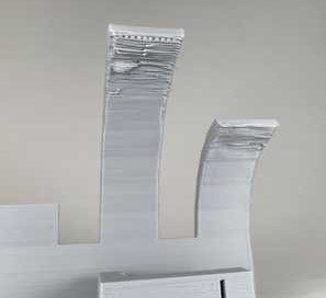
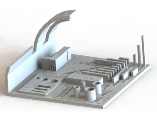
Different 3D printers can print differently based on a couple of factors. This differences in printing translates to the quality of print based on application. In most of the cases, we are looking at whether the printer can print the smallest details and if the printer can print at different angles.
Therefore, using unique designs that contains different situations can differentiate the 3D printers for all the different parameters. A number of differences could also result from the combination of the printer filament and the temperature of the nozzle.
For the current case we have PLA filament for a Makerbot 3D printer that has a range of nozzle temperature of 210 to 250 degree , and a heated bed around 80 to 110 Degree.
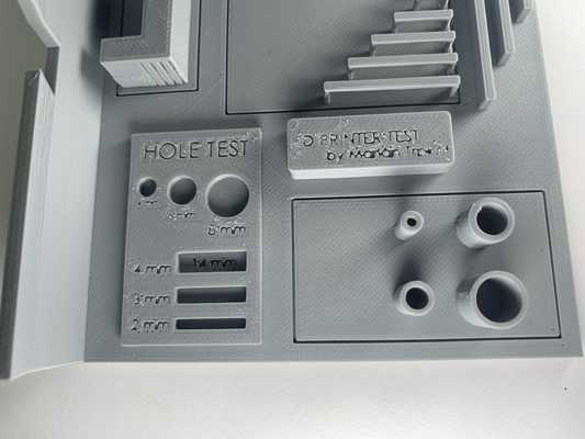
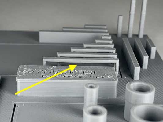
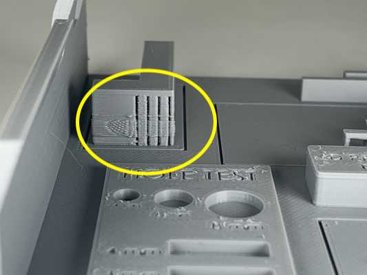
Therefore we made use of a more dynamic test model available at:
https://www.thingiverse.com/thing:2656594 to test print and check the print quality of the 3D Printer.
There are other extensive test prints available on all3dp.com
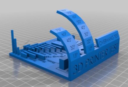
The test includes;
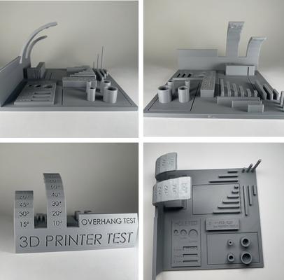
Comments: