Task to be carried out this week
During the Second week lecture hours by Prof. Neil, we were taught about the
The first week assignment included the following;Action Plan
| Date | Work Allocation |
| 2nd February | Prof. Neil's class on 2D and 3D design softwares |
| 3rd February | Installation of various 2D and 3D design software. Try 2D design softwares (Rastor-GIMP & Vector-Inkscape) |
| 4th February | Lecture on Solid works by local instructor. Trying to model using solid works |
| 5th February | 3D modeling using fusion 360 |
| 6th February | Rendering using fusion 360 |
| 7th February | Animation using fusion 360 |
| 8th February | Documentation and Local Review |
Introduction to 2D and 3D objects
The main task for this week was to try modelling our final project sketch using one 2D and one 3D design software. Before trying these softwares, U had to first ubnderstand the difference between 2D and 3D objects.
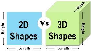
2-D design:2-D or 2 Dimensional designs are those with only X and Y coordinates, meaning 2D design
displays only the length and height information on a flat surface without depth. 2D designs are usually flat, designers must understand the appearance of the final product,
which may be difficult for people who do not have a technical background.
3-D design:3-D or 3 Dimensional design are those that has an additional coordinate 'z-axis' that gives a depth to the 2D designs. This gives the designs an appearance as perceived in real world.
This added depth allows the designs to be percived and understood by people without any technical backgroung.
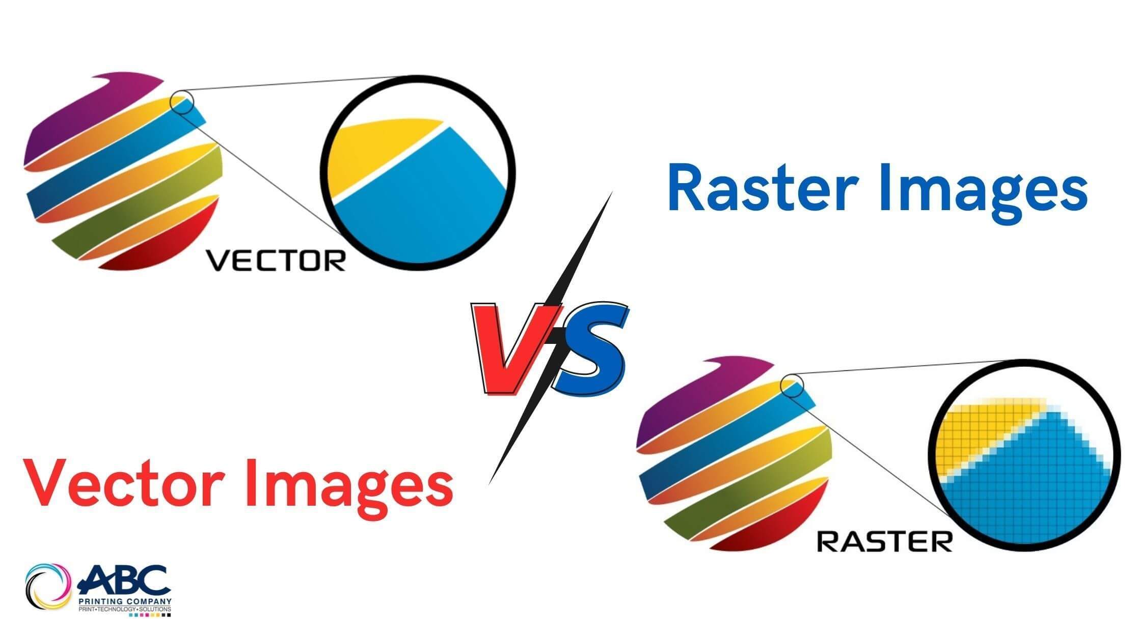
Rastor and Vector Images
Vector graphics also known as Scalable Vector Graphics(SVG) are digital art that is rendered by a computer using a mathematical formula that make up pioints and paths.
Because the vector images are made of paths and not pixals, they are resoultion independent making them infinitely scalable.
Raster images are made up of pixels which are tiny dots of different colors. Each pixal consist of a single color and these pixals arrange themseleves in certain way to make up a picture.
Because the images are dependent on the number of pixals it contains, rastor images are resolution dependent. Thus scaling affects the quality of the picture.
| Vector Images | Rastor Images |
| Vector graphics consist of anchored dots and connected by lines and curves. | Raster images are made of pixels, or tiny dots that use color and tone to produce the image. |
| They are resolution independent making them infinitely scalable | These graphics are resoultion dependent. thus the quality of graphics is affected when scaled up or down. |
| size of the files are relatively small | Larger file sizes which depends on the resolution |
| File types: ESP, SVG, AI | File types: BMP, GIF, JPG, PNG,TIFF |
| Vector design softwares: Inkscape, CoralDraw, Adobe Illustrator | Rastor Design Softwares: GIMP, Photoshop, MyPaint |
2D Rastor design using GIMP
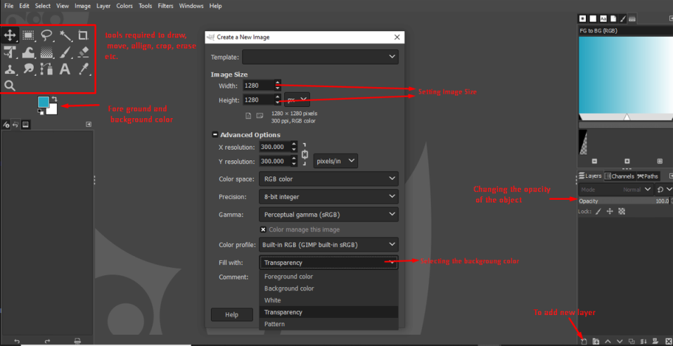
For creating my rastor 2D design object, I used the GIMP software. GIMP stands for GNU Image Manipulation Program and it is an open-source softwares that can be used for photo retouching, image composition and image authoring. I created a simple logo design using the tools available in the GIMP software.
When I open the software, the following page is displayed. There are multiple tools available to create images or to edit them. I cans select different background and also create objects using the eclipse and rectangle select options. We can also add layers and change the opacity of the various objects created. There is also the option to import images to edit them. There is also an erase tool to remove the errors or objects you donot want in your design.
I used the rectange and eclipse tools to create a basic outline for my logo design. Before creating the objects, I added guidelines to enable me to create the onjects at the center of my canvas.
To get the guidelines;
Go to Image → guide → New guide(by percent) → select the direction and position(50%) in the pop up box.
I drew two squares and a circle all on different layes to create a basic outline for my logo as shown in the picture below.
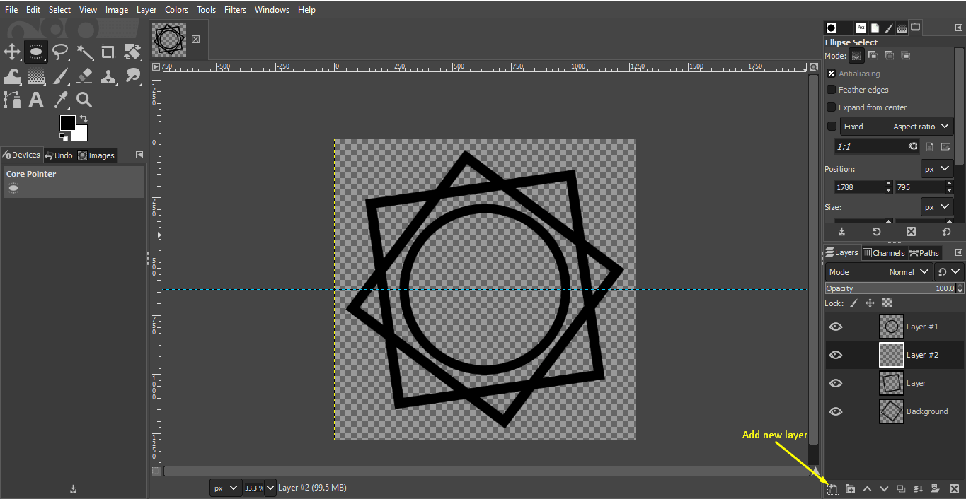
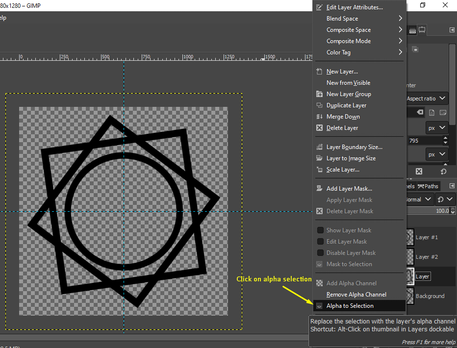
The next thing that I wanted to do was to make the overlapping sides of the square to appear like they are going over and under eachother.
To do that;
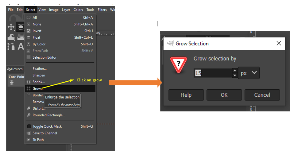
Add a new layer above the second square object layer → Right click on the second square object layer → Alpha to Selection → go to select option on the menubar → click on Grow → give 15% on the pop up box
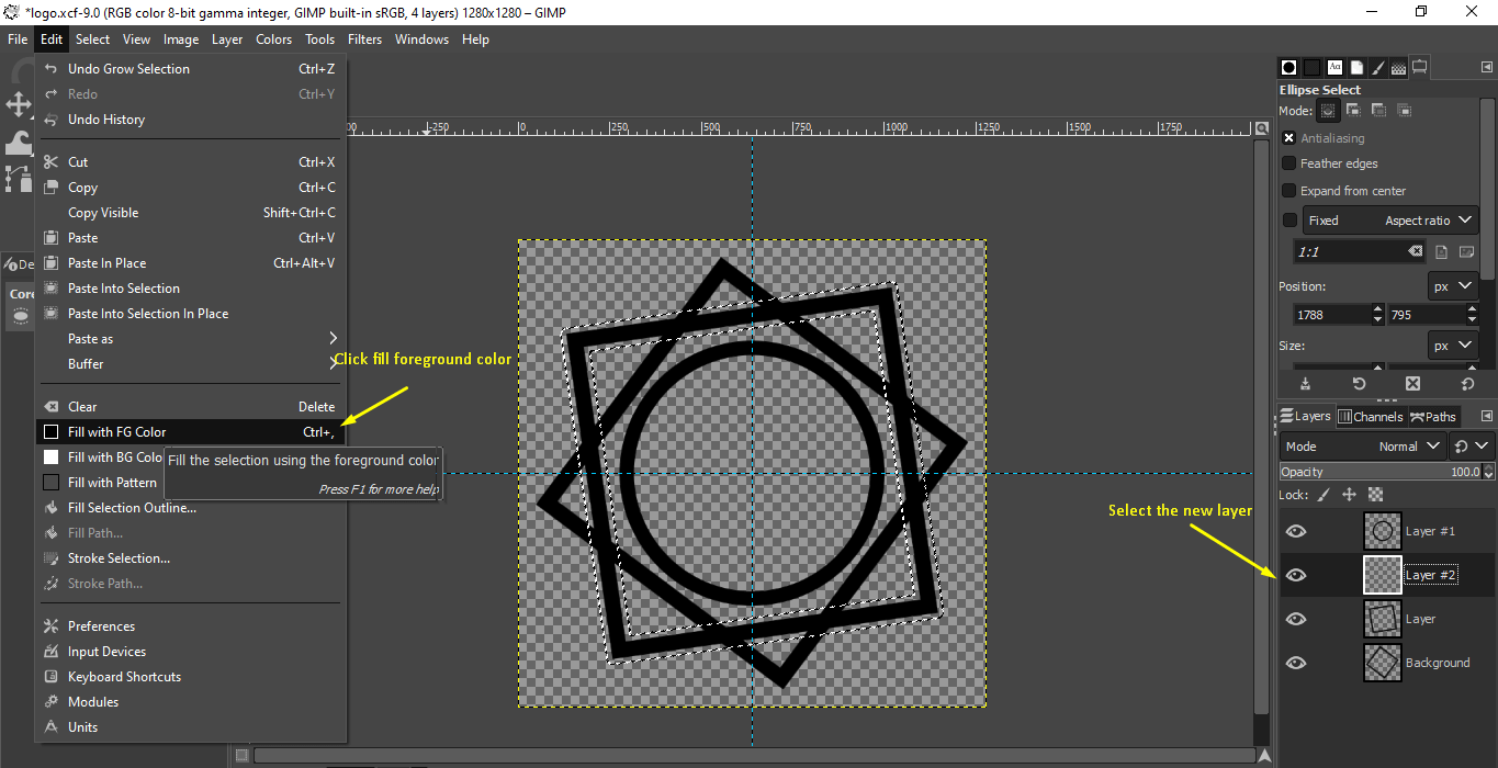
Select the new layer → click on edit on menu bar → select fill with foreground color.
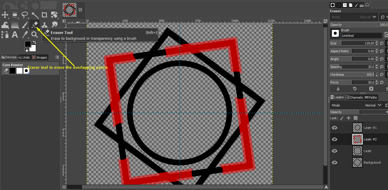
Next use the erasor tool on tool bar to erase the over lapping sides → Right click on new layer → select Alpha to selection → delete new layer.
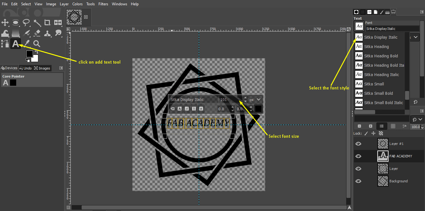
Lastly add text using the text tool on toolbar.
Final I changed the colors of the objects. Colors → curver → select the color
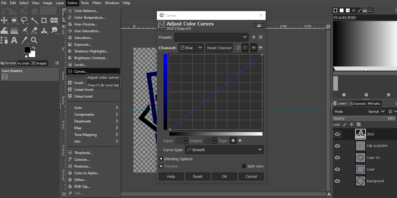
This is the final logo design that I created using the GIMP software
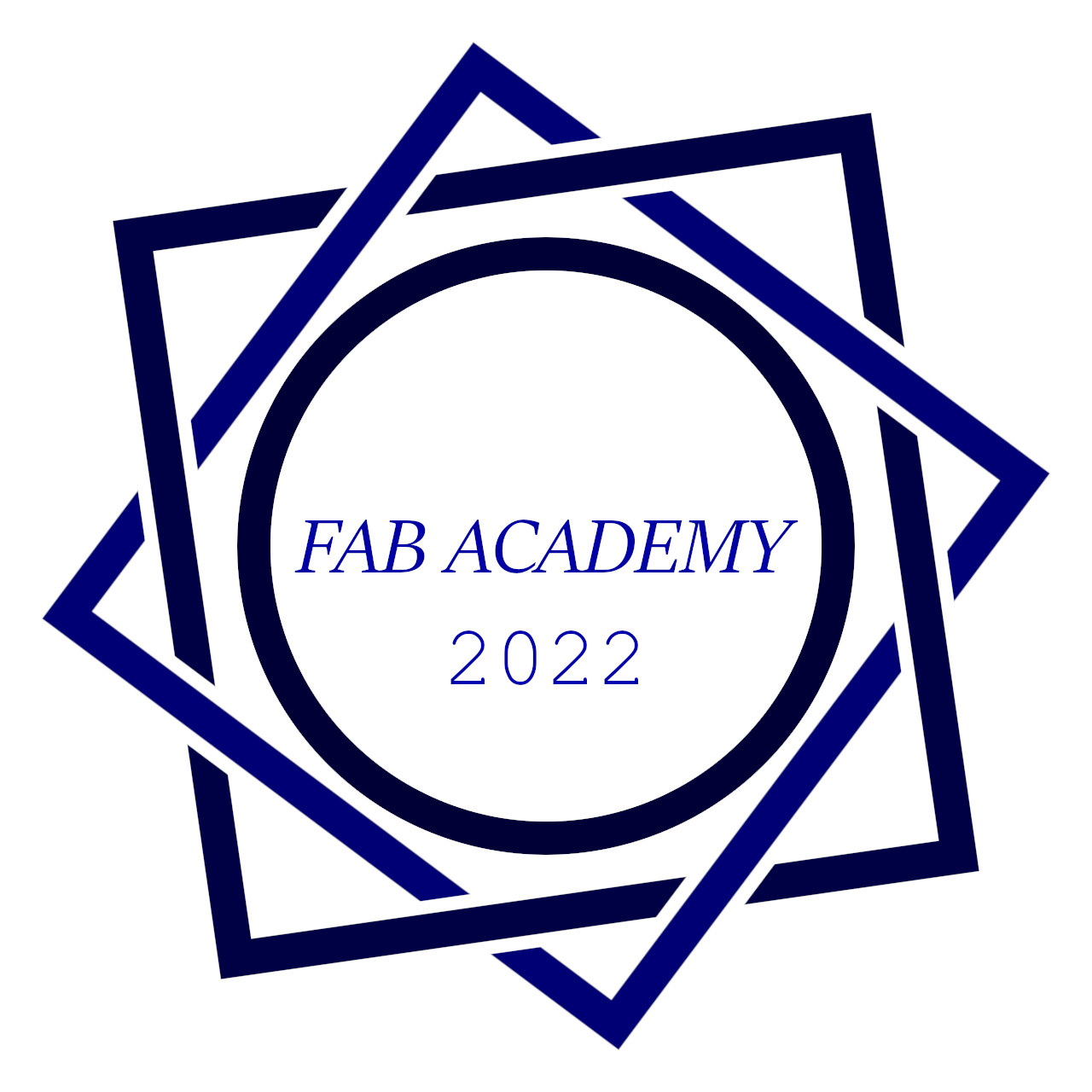
I made a GIF using the step by step pictures to show the overall step using in creating the logo
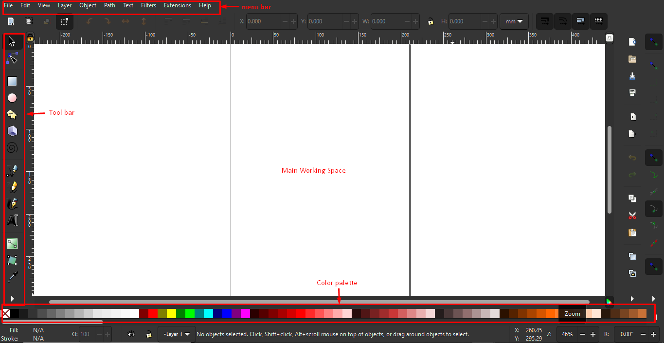
2D Vector design using Inkscape
I used the Inkscape software to create a 2D sketch of my final project. Inkscape is an open-source vector graphics editor used to create vector images. The files created using inkscape are usually in SVG(scalable vector graphic) format. However, it supports other formats and allows the import and export of other file formats such as jpg and png.
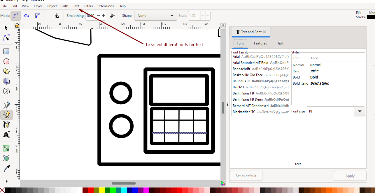
I used the inkscape software to create a basic 2D sketch of my final project. Inkscape porvides a number of tools for creating and editing objects.
Before I began sketching my project sketch, I tried using the various functions of Inkscape separately.
Here are some interesting functions I found when I played around with the tools
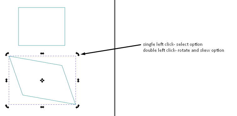
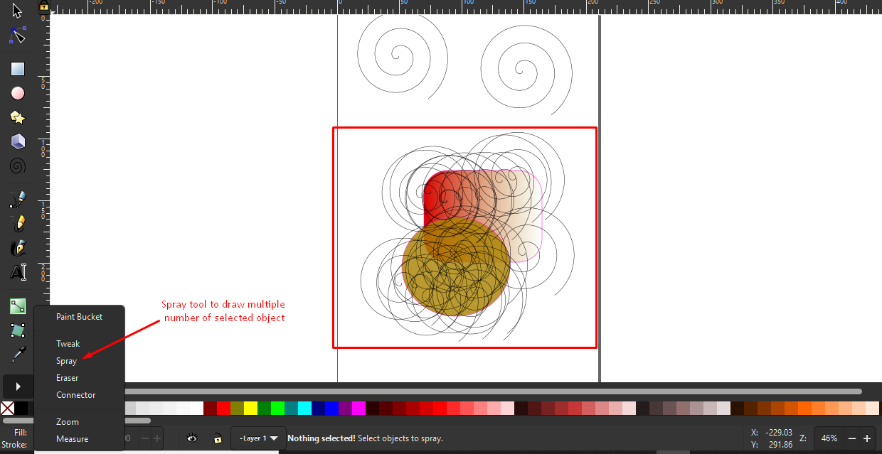
The spray tool on the tool bar can be used to draw multiple number of the same object. For this select the object → select spray tool → click and drag to draw multiple number of same object
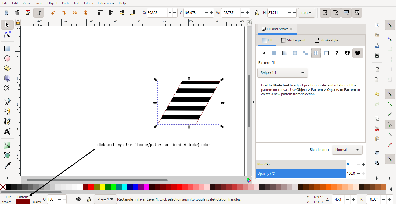
Aside from colors,we can also add textures, patterns and gradients to our objects
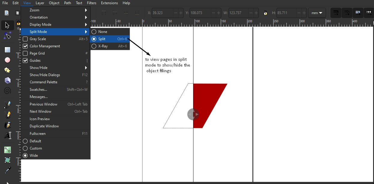
Under the view panel, there is an option to view the work space in split mode. This allows us to see the actual object created and the vector skeleton at the same time.
Under the path tab in the menu bar, there are a number of boolean functions. There is also the option to trace bit map. Using these tools I created a simple key chain
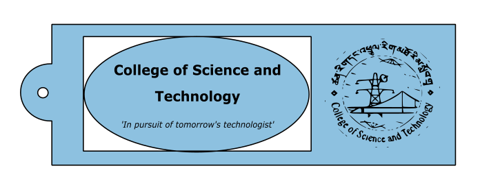
Click here to download the original SVG file
Creating a 2D sketch of my final project.
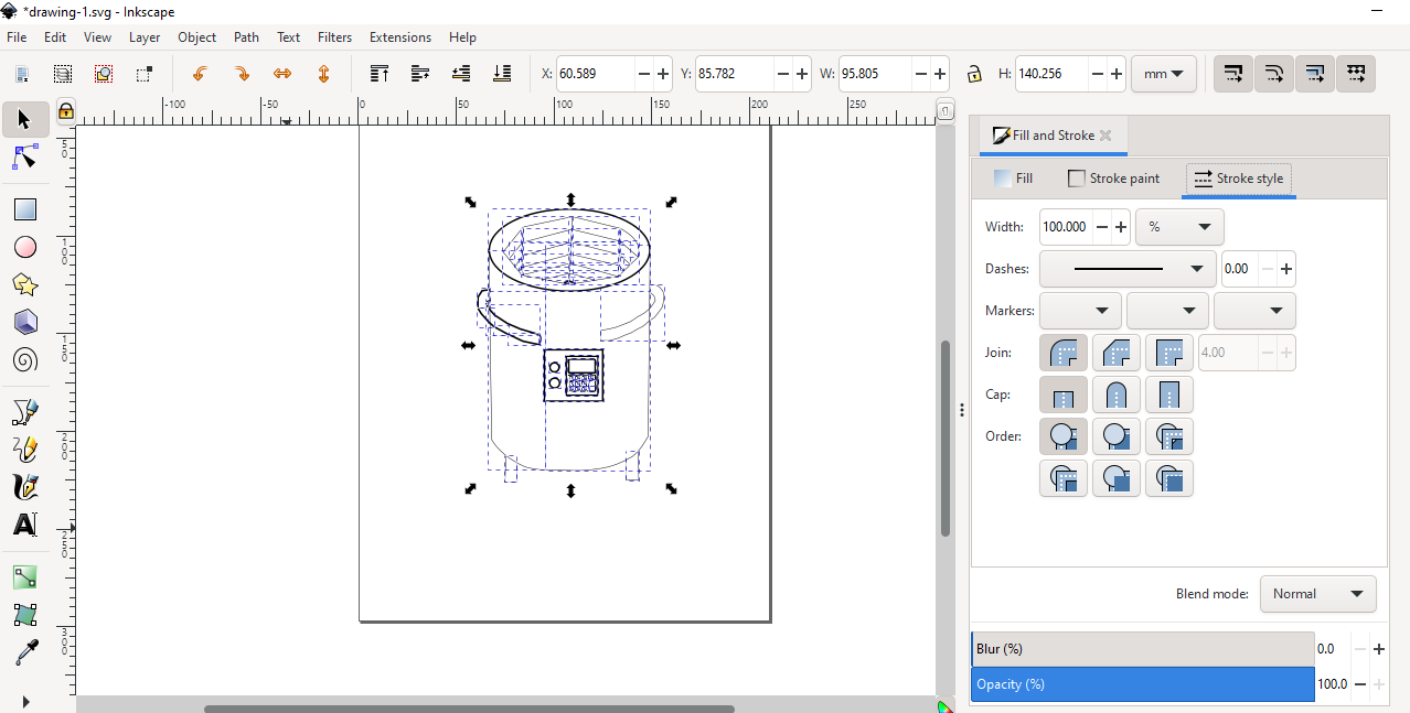
To make a basic sketch of my final project, I mostly used the free-hand drawing tools.
However for certain parts I used the eclipse and rectangle drawing tools. I used an online picture as a inspiration for making this sketch.
I also added some text using the text-tool.
This is the final 2D project sketch I created using the Inkscape software
Click here to download the original SVG file
3D Design Tools: Blender and Fusion 360
I selected Blender and Fusion 360 to create a 3D model of my final project. Since I am new to both the softwares, I faced a lot of challenges but it was a lot of fun to play around with the tools.
Blender
Blender is a free and open-source comper graphics software that can be used to create 3D models, animations, motion graphics, arts and scluptures, visual effects etc.,
Blender comes with a huge range of tool set such as 3D modeling, UV unwrapping, texturing, raster graphics editing,
sculpting, animating, match moving, rendering, motion graphics, video editing and many more.
Since I was new to the software and 3D model designing in general, I went through a lot of your tube videos. But the more I watched, the more confused I got.
So, I just went ahead and started to play around with the tools on my own to get a grasp of what each tool could do.
work space in blender
| Key | Function |
| middle mouse button | To orbit |
| Shift + middle mouse button | To Pan |
| g | Grab to move the object |
| r | To rotate the object |
| s | Scaling the object |
| Shift + A | Add new object |
| Alt + z | x-ray view |
| Shift + D | Duplicate |
| Tab | toggle between edit and object mode |
| F2 | Renaming Object |
| n | properties side bar |
| A and Alt +A | Select all and Deselect all |
| Alt + left click | Select whole edge |
| Ctrl + i | invert |
| h and Alt + h | hide and unhide |
| e | extrude |
| Ctrl + j | Join Object |
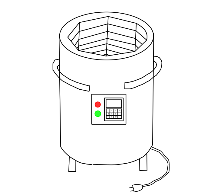
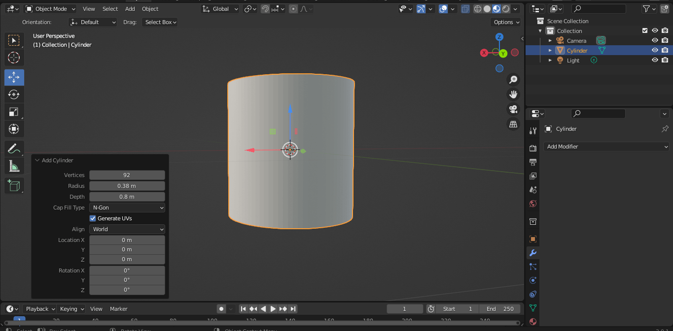
I tried using blender to create a basic 3D model of my final project. To do that I followed the following steps:
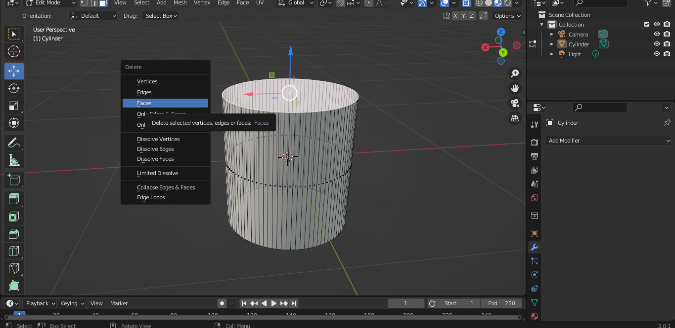
1. I started by drawing a cylinder object and deleting the upper face to create a hollow.
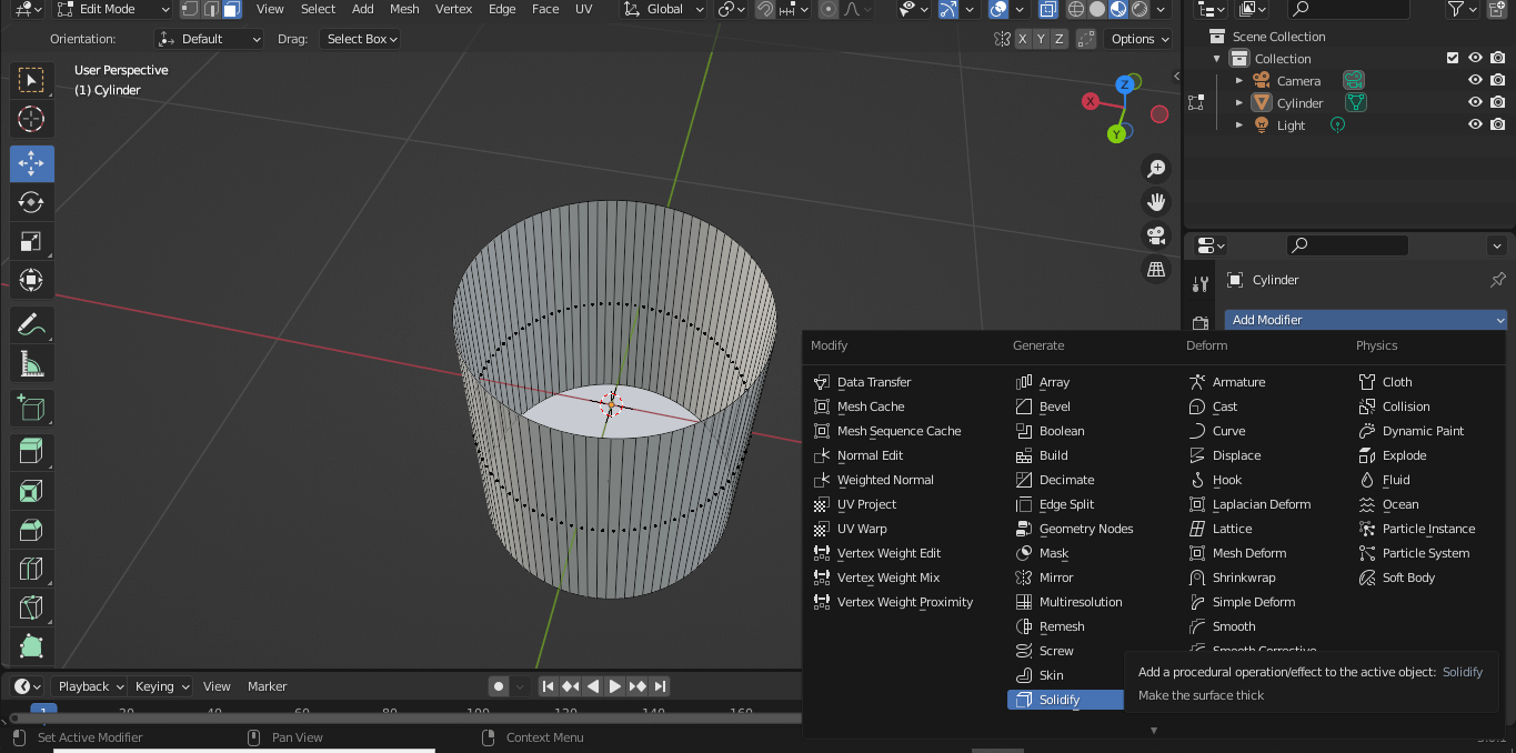
2. Next I wanted to to give some thickness to the edges of my cylinder. To do that, click on modifier → solidify → give thickness and offset value
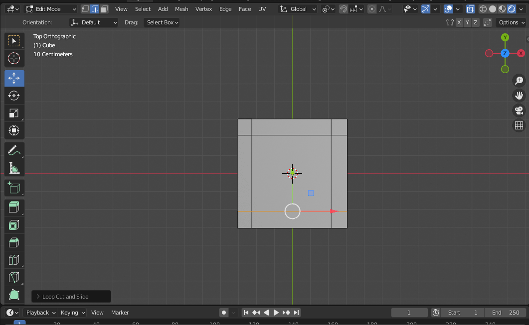
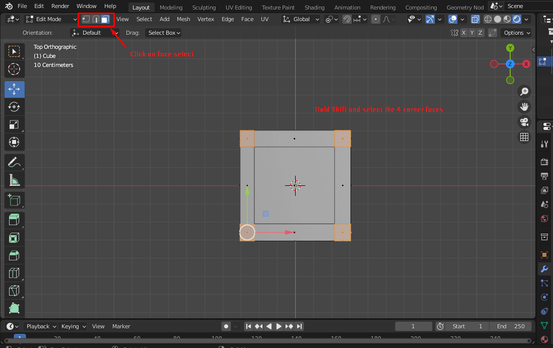
3. Next I tried creating a simple table on which I could mount my kiln model. For that I drew a cube and used 'Ctrl+r' to create edges at corner for extrusion.Then I selected the 4 faces at the four corners.
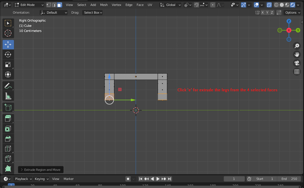
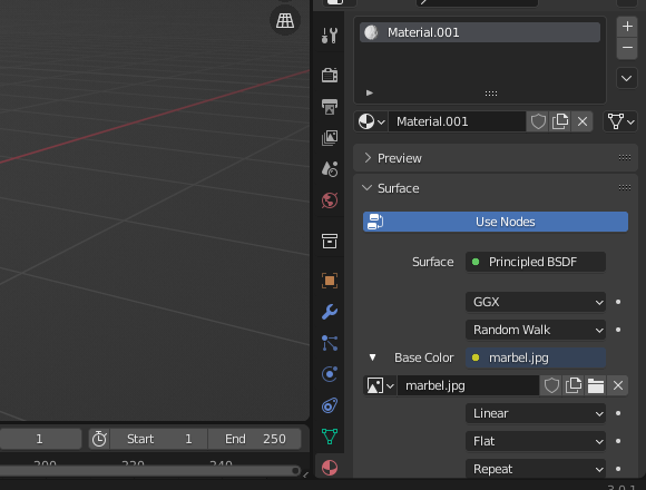
4. I used the 'e' shortcut key to extrude the for corner faces to make table legs. I also tried to change the material for my table. For this;
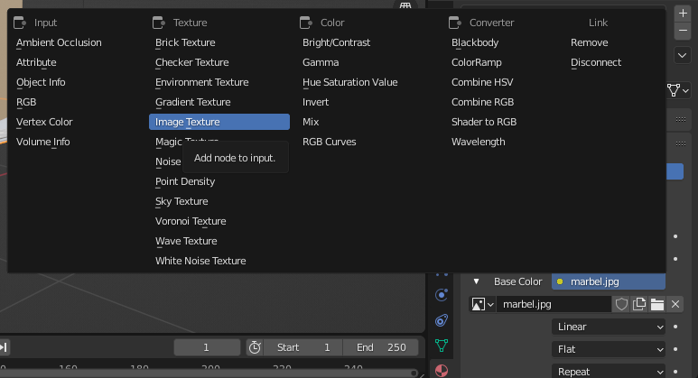
select the object → click materials tool → add new → base color → image texture → uploade the image f the texture you want
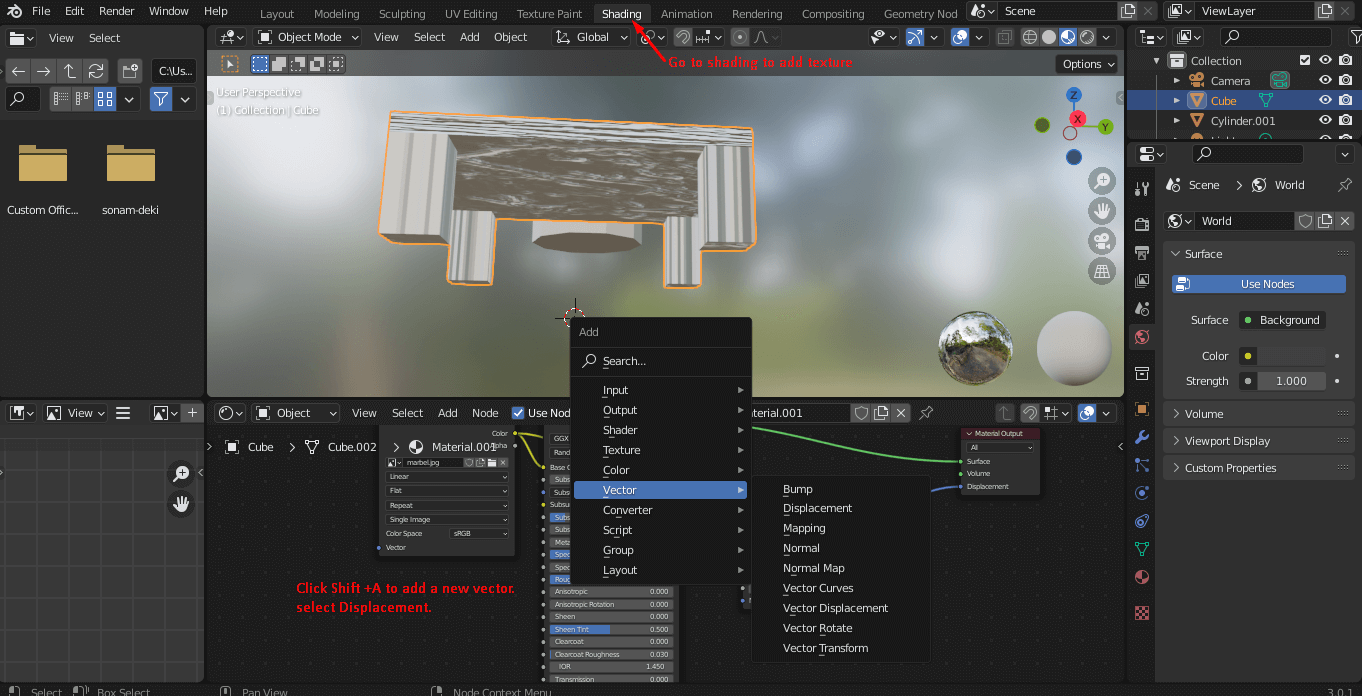
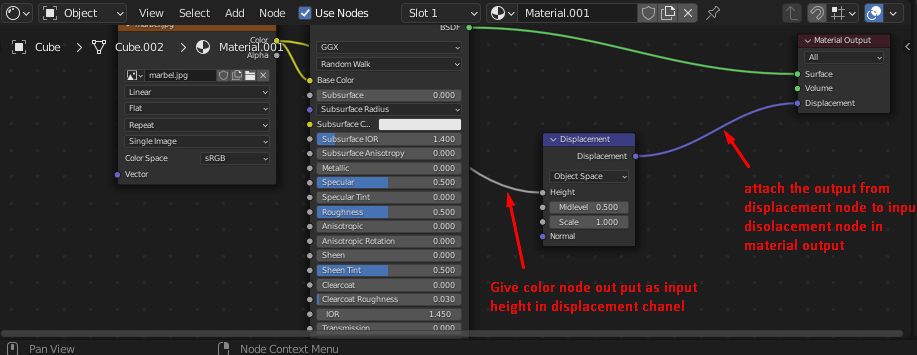
5. I tried to add shading to the table material
6 . In similar way, i added some material to my kiln model. I also tried to make an internal stand using extrude tool. I also added an power box to the cylinder i created.
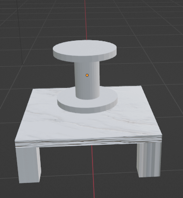
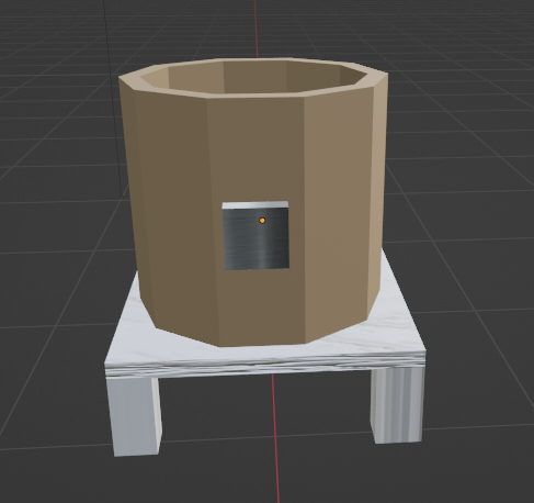
FInally this was how my model came about
.gif)
click to download to original file
Fusion 360
Fusion 360 is a cloud based 3D modelling and a CAD program software. It is one of the most well known and 3D modelling and manufacturing software.
Since Fusion 360 is cloud based, it is a great platform for collaborative 3-D modelling and CAD projects.
I tried to create a 3D model of my final project using Fusion 360 and following are the steps i followedto create the final model
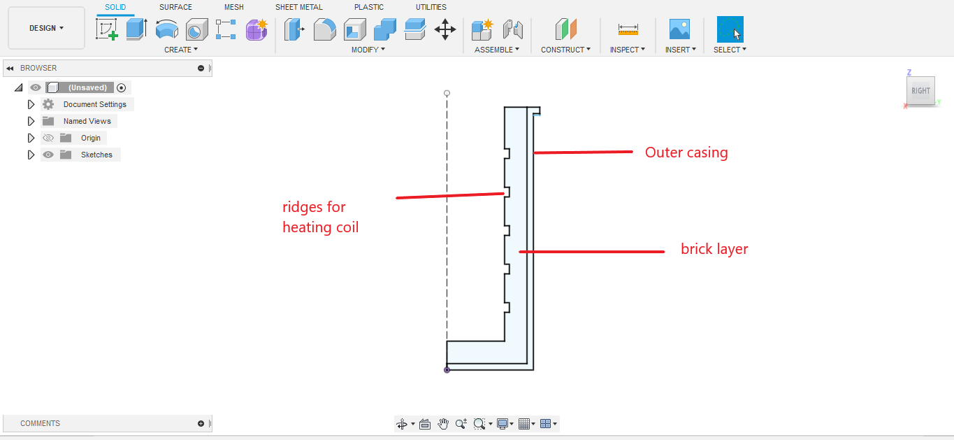
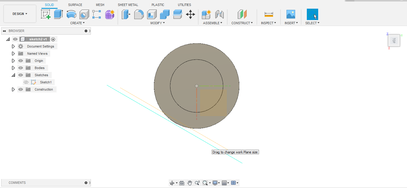
1. Before making the 3D model, I had to first sketch a 2D design. To do that I clicked on sketch option
→ select a plane on which I wanted to sketch my design → made a 2 D design for my model using line tool. I also gave dimensions to the lines.
2. Once I was done with my 2D sketch, I clicked on finish sketch. Then I used the revolve tool to create my cylinder. For this go to create → revolve → select my sketch for plane and the axis. → clcik ok.
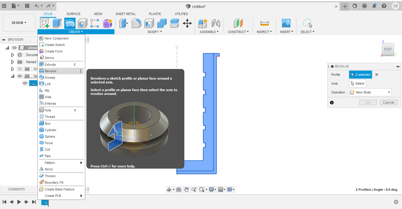
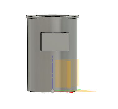
This is how the cyliner came about.
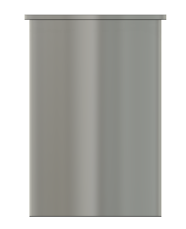
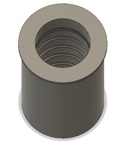
And this is how it looks inside
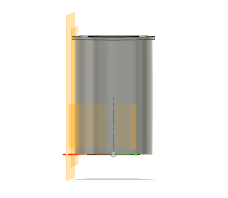
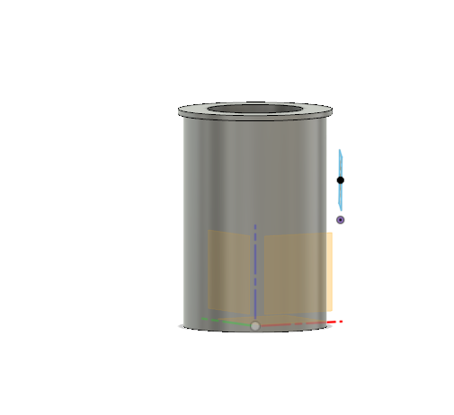
3. Next, I wanted to model the control box on the cylinder. To do that, tutorial I had to first create a plane on the cylinder surface.
For that go to construct → select tangent plane → select the face to which you want the tangent plane to be → set angle with reference to any of the origin plane → click ok
Then I also created an off-set plane with a refernce to the tangent plane I created. This was done to specify the dimension/ thickness of my control box.
I followed this youtube tutorial for making a plane on cylinder
4. Then I selected the new plane I created and skecthed a rectangle on it.
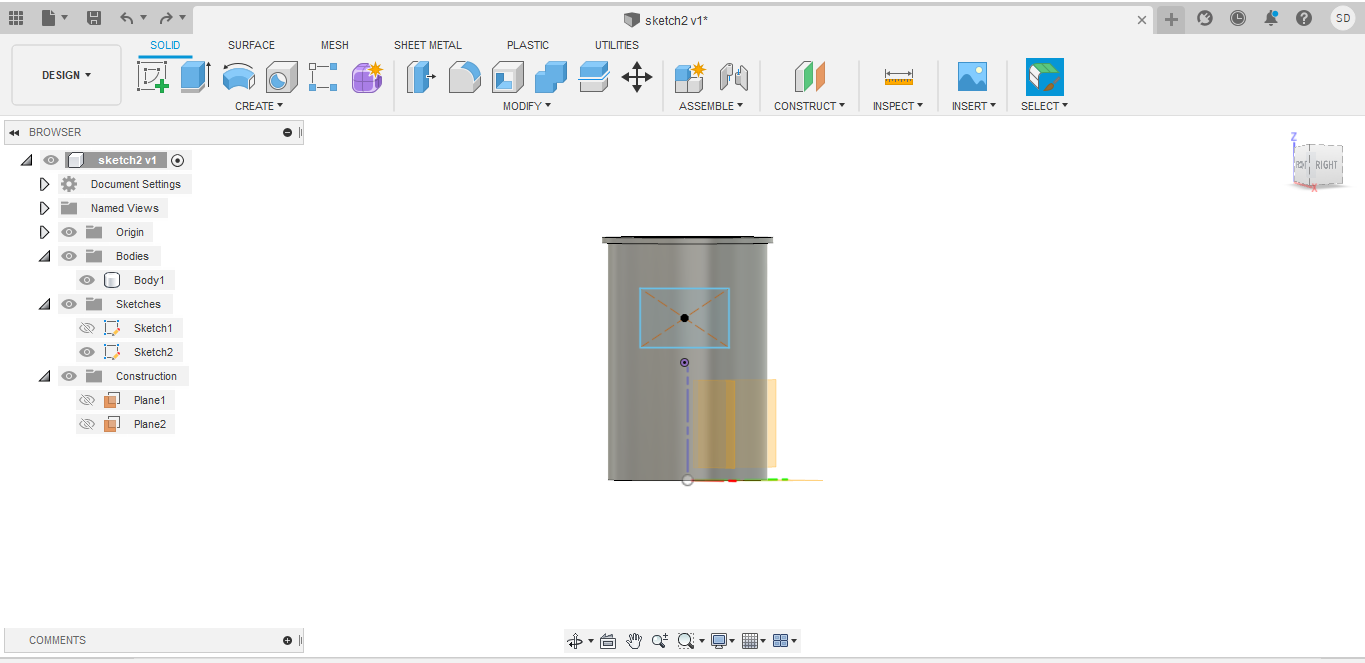
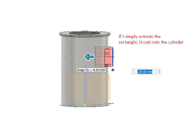
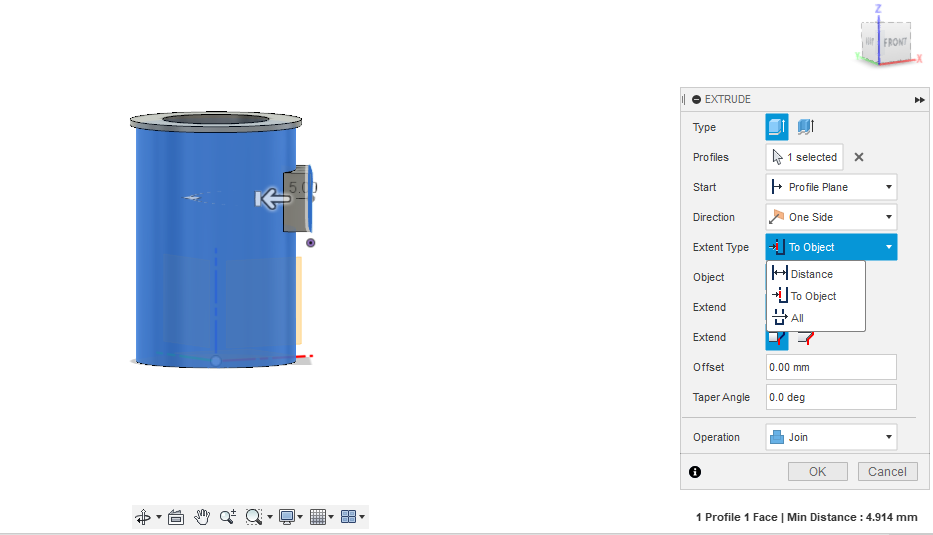
5. I used the extrude tool on the rectangle sketch to get a cuboid for my control box. I learned that, If I simply tried to extrude the rectangle by distance
it cuts into my cylinder. I didnt want that. So I selected the extrude type as 'to object' to get a clean extrusion till my cylinder surface.
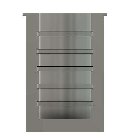
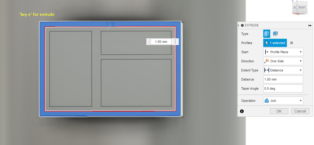
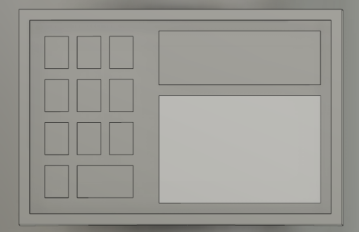
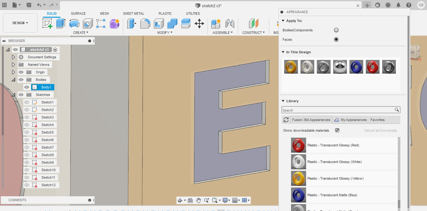
6. I wnated to add some detailing to my control box. To do that, I selected sketch and selected the front face of the control bax as a plane for the new sketch.
I made 3 rectangles, one for the LCD screen, one for number pad and one for switches.
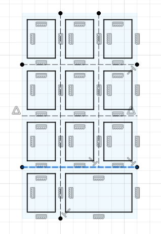
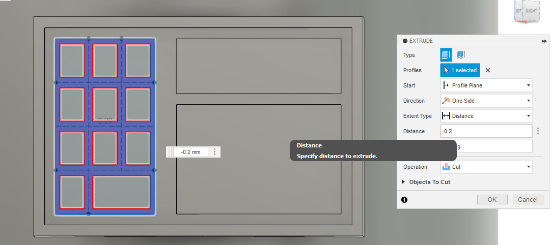
7. For the next step, I started working on the number pads. For that;
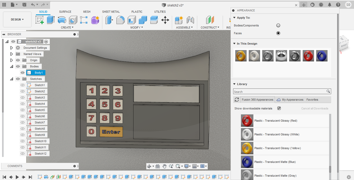
I selected the tallest rectangel as my plane for sketching → I than made some reference lines → I made rectangles for number buttons. → finish sketch. → I then gave a negative extrusion amount to create the number buttons look like they were embedded on the control box
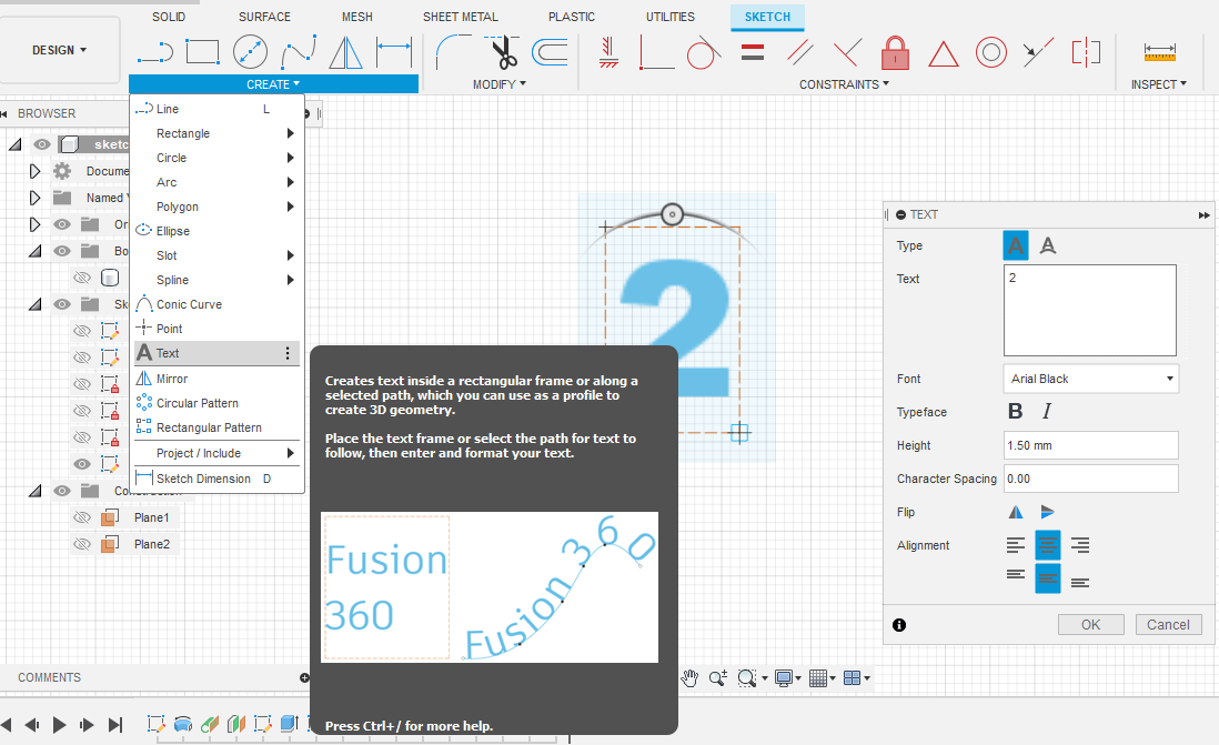
8. Then, I add numbers on each of the number buttions using the text tool. I gave a negative extrusion amount for the numbers to look like they were engraved on th enumber buttons
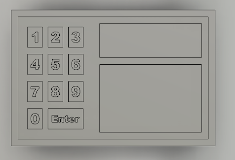
This was the final look
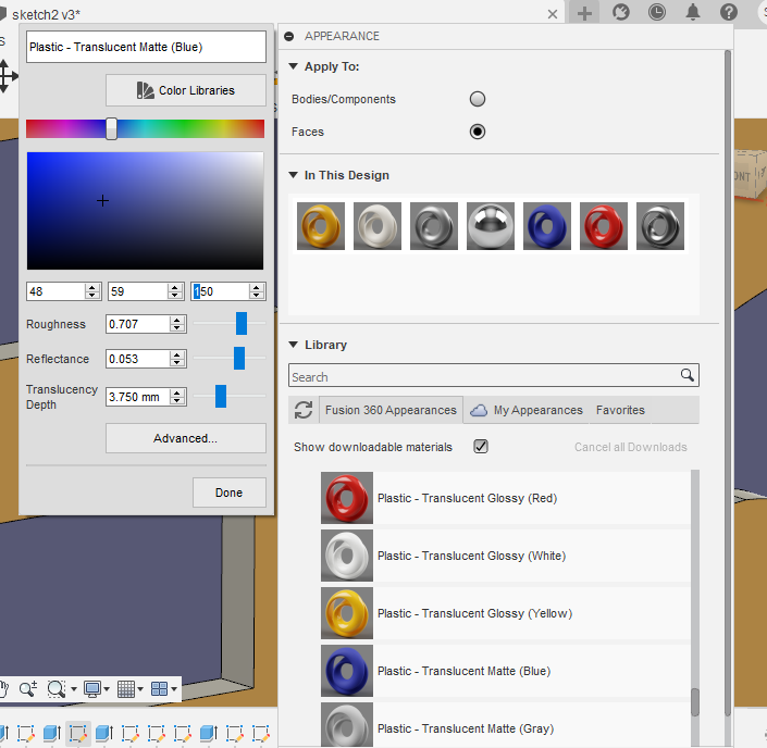
9. Next, I went on to add some material to my model. For this, go to modify → select appearances → select the materials you want → drad and drop in te face you want the material to be applied to
I learned that you can also change the colors of the material you choose. select the material and double click on it
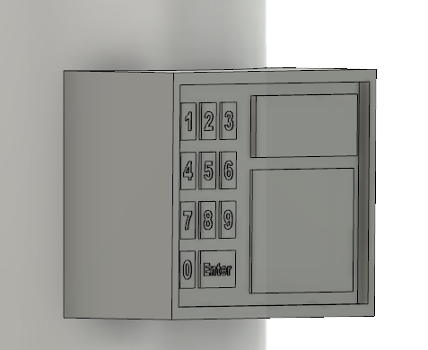
10. For the last step, I tried to apply some rendering effects on the model. For this select rendering mode. I tried to chnage the environment and light settings.
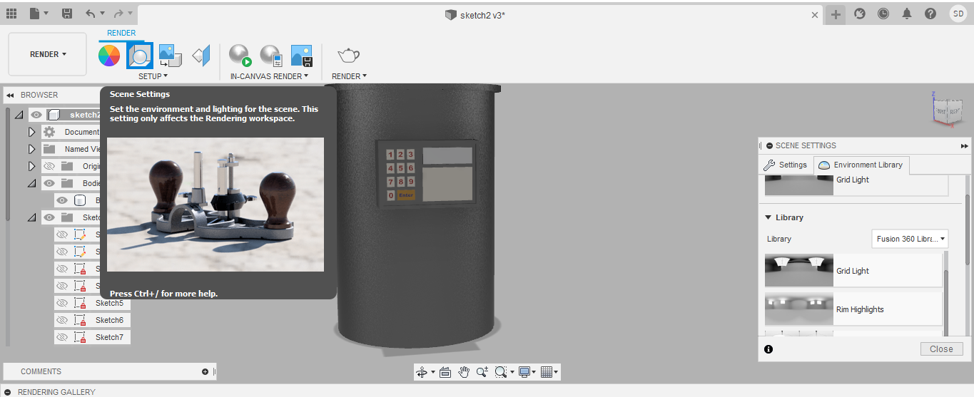
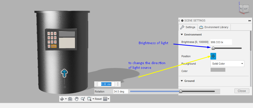
We can save an png image file in fusion 360
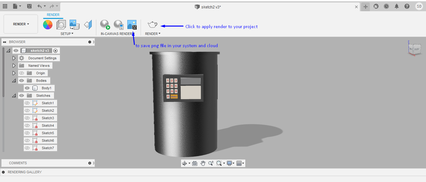
This was the final model I made.
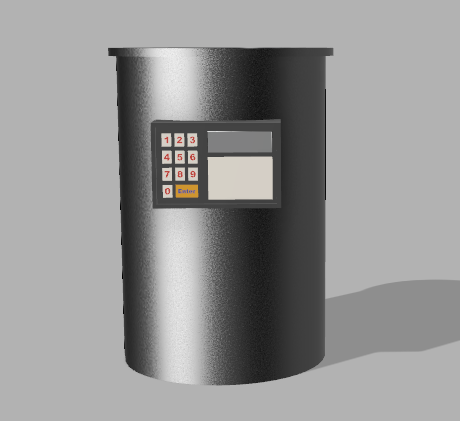
click to download to original file
There are still a lot of modifications that I need to make to my model. I still need to learn to include the coil on the ridges I created. I also need to add a base for the kiln. I hope to keep improving my model till the end of Fab Academy.
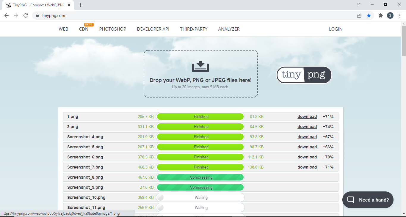
Image Compression
For compressing my images for tthe documentation, I have been using an online site called 'Tinypng.com'. I can upload upto 20 images at a go or files up to 5MB in size. I can download all the compressed images at once in the form of zip file or it can be downloaded individually.