Task to be carried out this weekGroup Assignment
Action Plan
| Date | Work Allocation |
| 4th May | Global classes by Prof. Neil |
| 5th May | Lecture on processing software by Rico-san |
| 6th May | Larning about Processing 3 software |
| 7th May | Designing the application interface |
| 8th May | Connecting the application to my board |
| 9th May | Connecting the application to my board |
| 10th May | Documentation |
Introduction to Processing 3
Processing 3 is programming for artists. The processing 3 software is a flexible software sketchbook and a language for learning how to code within the context of the visual arts.
Since its launch in 2001, the software has promoted software literacy within the visual arts and visual literacy within technology.
Some of the advantages of the processing 3 software are;
Interfacing with Processing software
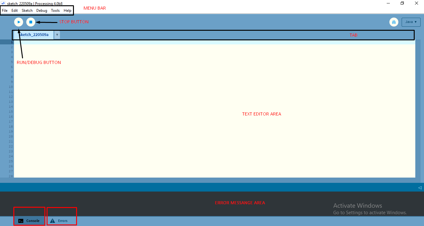
The processing 3 software has a similar interface to that of an Arduino IDE which made its usage easier for me. The Processing Environment includes a text editor, a compiler, and a display window.
Programs are written in the Text Editor and started by pressing the Run button. In Processing, a computer program is called a sketch. Sketches are stored in the Sketchbook, which is a folder on your computer
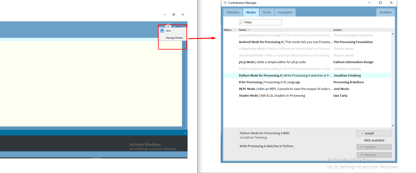
The Processing 3 supports a number of programming language including java, python, R-code etc.,. There are also features to add and select the languages.
Rico-san gave us a hands-on virtual lecture session on working with the processing 3 software.
I used the java language to write the code for creating the interface. I tried a couple of codes after the lesson to understand the flow of the program.
I referred to the notes shared by Rico-san and also the Processing Interactivity Tutorials published by MIT Press.
Trying out codes in Processing software
In processing 3, there are two main functions; setup() function and draw() function.
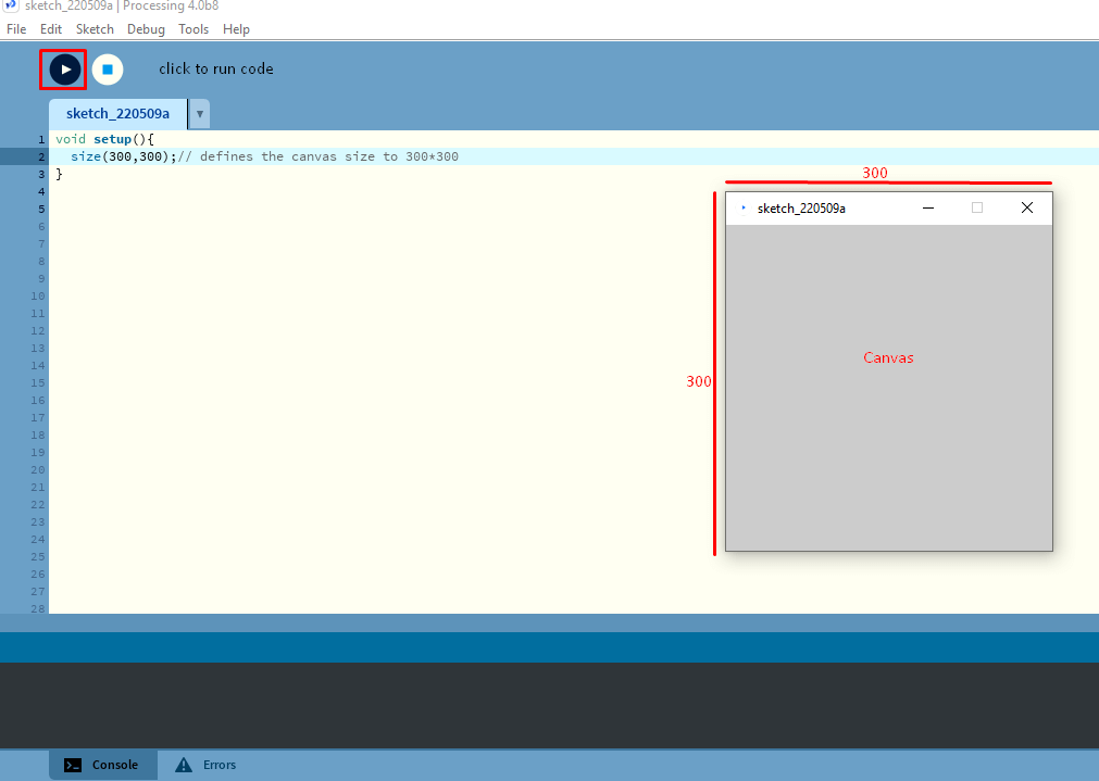
The setup() function is an initialization function that runs once at the begining of the program and it is in this function that we write codes for configuration and settings for the interface such as defining the size of the canvas.
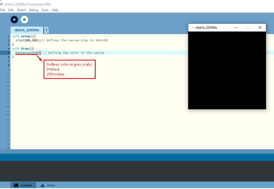
The The draw function works similar to that of the loop function in Arduino IDE and runs multiple times in a loop until we tell the program to stop and it contains the codes for interface design and interface working/functionality.
Customizing the Canvas
In processing, we can define the size of the output canvas. It is defined under the setup() function. The code block used for defining the size is as follows;
Adding shapes to the interface
In processing, we can add a number of different types of shapes. We use the following codes to add the shapes;
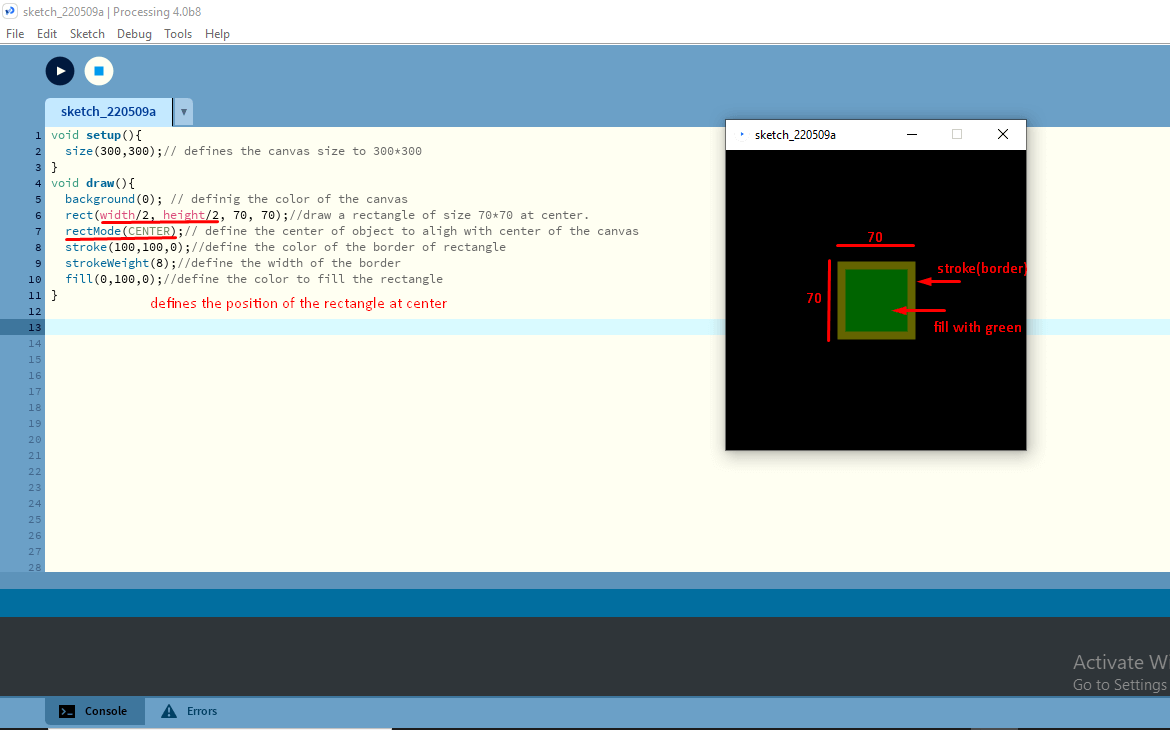
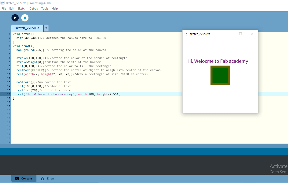
Adding TEXT
Similar to adding shapes, we can add text and numbers to our interface. I used the following code block to add the text;
Mouse Events: Turning shapes into functional buttons
For the next step, I tried to conver the shapes I added to my canvas into functional buttons. To do that, I used codes for mouse events. Some of the codes I used are;
Application Development
For this week's assignment, I used the Processing software to build a user interface that communicates with my board. I plan to use the board I made during my output week. The first step I did was sketch out the idea on how I wanted the interface to look and what it was to do.
I wanted the to make multiple buttons and when clicked, I wanted text to be displayed on the LCD connected to my board. I used if statements and functions to make the interface more interactive.
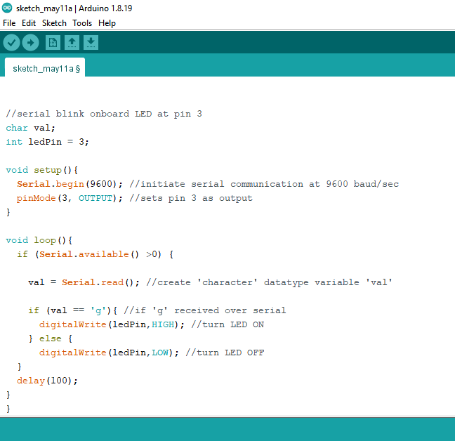
Before I began with programming for the LCD display, I tried a simple LED blinking code in which the LED blinks when it received serial signal from the button press.
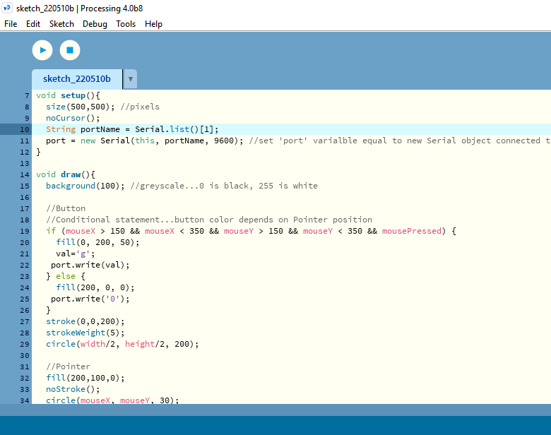
The Arduino code for LED blinking and the processing code for button interface was written by Rico-san and was the code used during the local class for demo. The code can be seen below;
I already has test LED on my output week board, so I made all the connections and tried programming with Arduino UNO board.
But I kept getting the processor not responding error. Since I kept facing the issue with Arduino, I tried programming with USBTiny and it actually worked.
However, I couldn't get the PORT number for USBTiny. When I looked online, I learned that USBTiny doesn't create a serial port and cannot do that. It actually programs the board directly, using the ISP connection, not Serial.
I didn't know how to go ahead so I tried getting help from the local instructors. I got help from Rico-san and we tried solving the issue together through Zoom.
The first thing we did was try to program the board again with the Arduino. We tried and it still kept giving the same issue of Programmer not responding.
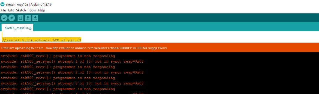
Hence, we tried to program the Arduino board for LED blink to check if the programming code was the issue. The output pin number was changes from 3 to 13 and we loaded the program.
Then I ran the processing code and pressed the button on the processing interface. On pressing, the LED blinked but with great delay. Later we found that, we should reduce the delay on program and it worked.
Next, we tried programming my board with the Arduino but the issue persisted. So, we moved to using USBTiny to program my board. The code loaded successfully.
To get the port number, I connected the FTDI connector to my board. Then I ran the processing porgram but a blank canvas kept poping up.
We tried changing the port numbers but and found out that the wrong port number was defined in the processing interface.
We had to define the port number of the FTDI connector which was the third port number but I had defined 1 for port number on my processing code.
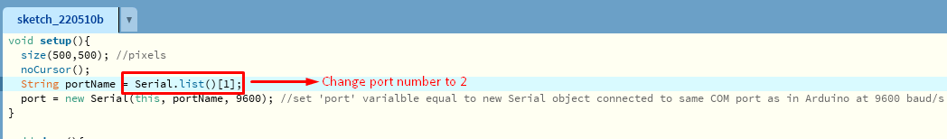
I also learned from Rico-san that when reading the port number, we start with '0' for the first port and '1' for second and so on. The port number was changed and the I ran the processing code again.
This time it worked and the button interface was displayed.
Sadly, this was not the end of the issues we faced. This time both the processing and the arduino worked but somehow there were issues in communication between the interface and the board.
The LED didn't blink when button was pressed. I looked on the internet about the issue and found that there may be some issues with the connections on the board.
I used a multimeter to check the connection and as mentioned on the net, my MISO connection had some issues. Suhas sir helped me in rectifying this connection issue and this time the code for both arduino and processing worked. Thank god!!!
For the next step, I modified Rico's code to change the interface to my liking and on the arduino, I combined my output week's code with Rico's code to make a text display on LCD when the button gets pressed. Similar to the steps followed before,
I loaded my board with the arduino program and then ran the processing code. when I pressed the button, the text started to get displayed.
Output for Week14