
Week 12
- CategoryInput Device
- Sessions Date:27/04/2022
- Assignment:
- Group Assignment
- probe an input device's analog levels and digital signals
- Individual Assignment
- measure something: add a sensor to a microcontroller board that you have designed and read it
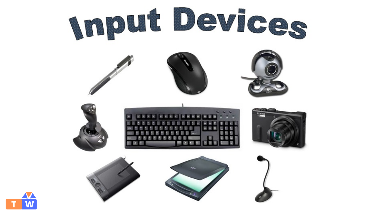
What is Input devices?
An input device is a peripheral device that accepts data and feeds it into the computer. For an example, mouse, mic,speaker, etc...
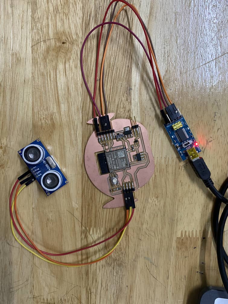
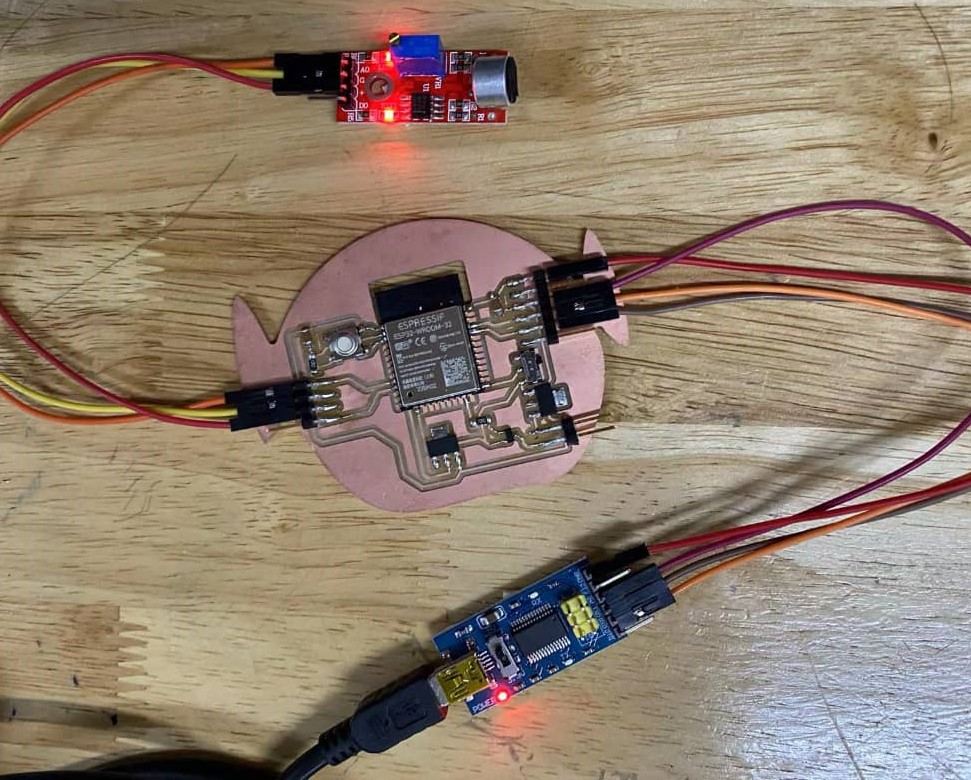
For this week, I used the mic sensor and ultrasonic sensor as the input devices. I will be using the same board as of the outut week for this week.
Ultrasonic sensor
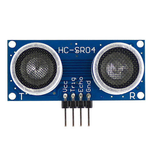
An ultrasonic sensor is an electronic device that measures the distance of a target object by emitting ultrasonic sound waves, and converts the reflected sound into an electrical signal.
Ultrasonic waves travel faster than the speed of audible sound (i.e. the sound that humans can hear).
Ultrasonic sensors have two main components: the transmitter (which emits the sound using piezoelectric crystals) and the receiver (which encounters the sound after it has travelled to and from the target).
Ultrasonic Sensor Pinout Configuration
1.VCC- The Vcc pin powers the sensor, typically with +5V
2.Trigger- Trigger pin is an Input pin. This pin has to be kept high for 10us to initialize measurement by sending US wave.
3.Echo- Echo pin is an Output pin. This pin goes high for a period of time which will be equal to the time taken for the US wave to return back to the sensor.
4.Ground- This pin is connected to the Ground of the system.
HC-SR04 Sensor Features
Operating voltage: +5V
Theoretical Measuring Distance: 2cm to 450cm
Practical Measuring Distance: 2cm to 80cm
Accuracy: 3mm
Measuring angle covered: 15°
Operating Current: 15mA
Operating Frequency: 40Hz
Connecting Ultrasonic sensor to the controller board
Refering the pinout diagram for Ultrasonic sensor I connect the Ultrasonic sensor to my board. And using a FTDI connector I connected it to my PC.
1.VCC - VCC
2.GND -GND
3.Echo - Pin 25
Coding
After the connections, I ran the coding as below
      /*
        Ping))) Sensor

        This sketch reads a PING))) ultrasonic rangefinder and returns the distance
        to the closest object in range. To do this, it sends a pulse to the sensor to
        initiate a reading, then listens for a pulse to return. The length of the
        returning pulse is proportional to the distance of the object from the sensor.

        The circuit:
      	- +V connection of the PING))) attached to +5V
      	- GND connection of the PING))) attached to ground
      	- SIG connection of the PING))) attached to digital pin 7

        created 3 Nov 2008
        by David A. Mellis
        modified 30 Aug 2011
        by Tom Igoe

        This example code is in the public domain.

        https://www.arduino.cc/en/Tutorial/BuiltInExamples/Ping
      */

      // this constant won't change. It's the pin number of the sensor's output:
      const int pingPin = 25;

      void setup() {
        // initialize serial communication:
        Serial.begin(9600);
      }

      void loop() {
        // establish variables for duration of the ping, and the distance result
        // in inches and centimeters:
        long duration, inches, cm;

        // The PING))) is triggered by a HIGH pulse of 2 or more microseconds.
        // Give a short LOW pulse beforehand to ensure a clean HIGH pulse:
        pinMode(pingPin, OUTPUT);
        digitalWrite(pingPin, LOW);
        delayMicroseconds(2);
        digitalWrite(pingPin, HIGH);
        delayMicroseconds(5);
        digitalWrite(pingPin, LOW);

        // The same pin is used to read the signal from the PING))): a HIGH pulse
        // whose duration is the time (in microseconds) from the sending of the ping
        // to the reception of its echo off of an object.
        pinMode(pingPin, INPUT);
        duration = pulseIn(pingPin, HIGH);

        // convert the time into a distance
        inches = microsecondsToInches(duration);
        cm = microsecondsToCentimeters(duration);

        Serial.print(inches);
        Serial.print("in, ");
        Serial.print(cm);
        Serial.print("cm");
        Serial.println();

        delay(100);
      }

      long microsecondsToInches(long microseconds) {
        // According to Parallax's datasheet for the PING))), there are 73.746
        // microseconds per inch (i.e. sound travels at 1130 feet per second).
        // This gives the distance travelled by the ping, outbound and return,
        // so we divide by 2 to get the distance of the obstacle.
        // See: https://www.parallax.com/package/ping-ultrasonic-distance-sensor-downloads/
        return microseconds / 74 / 2;
      }

      long microsecondsToCentimeters(long microseconds) {
        // The speed of sound is 340 m/s or 29 microseconds per centimeter.
        // The ping travels out and back, so to find the distance of the object we
        // take half of the distance travelled.
        return microseconds / 29 / 2;
      }
Hero Shot video
Mic Sensor
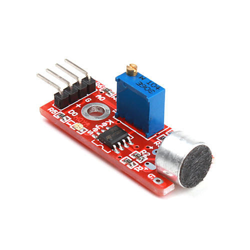
A microphone is a sensor or transducer which converts sound to electric signals. There are many types of microphones, but nowadays microphones are mainly divided into two categories: dynamic microphones and condenser microphones. Both types generate signals from changes in the air pressure.
Below is a pinout diagram for mic sensor
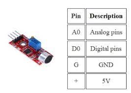
Refering the diagram above I connected the Mic sensor to the controller board.
1.VCC - VCC
2.GND -GND
3.AO - Pin 25
Coding
After connecting the pins, I uploaded the following code
      /*
        AnalogReadSerial

        Reads an analog input on pin 0, prints the result to the Serial Monitor.
        Graphical representation is available using Serial Plotter (Tools > Serial Plotter menu).
        Attach the center pin of a potentiometer to pin A0, and the outside pins to +5V and ground.

        This example code is in the public domain.

        https://www.arduino.cc/en/Tutorial/BuiltInExamples/AnalogReadSerial
      */

      // the setup routine runs once when you press reset:
      void setup() {
        // initialize serial communication at 9600 bits per second:
        Serial.begin(9600);
      }

      // the loop routine runs over and over again forever:
      void loop() {
        // read the input on analog pin 0:
        int sensorValue = analogRead(25);
        // print out the value you read:
        Serial.println(sensorValue);
        delay(1);        // delay in between reads for stability
      }
Hero Shot Video
Group Assignment
Here is the link to group assignment.
Files
Source code for ultrasonic sensorSource code for Mic sensor