
Week 6
- Category: Electronic Design
- Sessions Date: Feb, 2022
- Assignment:
- Group Assignment
- test the design rules for your 3D printer(s)
- Individual Assignment
- redraw an echo hello-world board
- add (at least) a button and LED (with current-limiting resistor) check the design rules, make it, and test that it can communicate
- extra credit: simulate its operation
During our Pre-Fabacademy, we did cover on the electronic design and even made our ow Hello board. Though we don't have access to lab for the practicals, we were able to understand the fundamentals in designing our board.
Getting to know the Components
😷
I think getting to know the components and understanding to why we use them is very important. Learning all the basics from scratch was quite a challenge but was fun. Our Fabguru Suhas did an amazing job explaining it in the simpliest way.
- Ribbon Cable-a cable for transmitting electronic signals consisting of several insulated wires connected together to form a flat ribbon.
So for those who are new to electronics, its pretty easy to differentiate the ribbon cable, it comes in Rainbow color.
For our hello board we need to connec the IDC connector to the ISP pin header. - An electrical switch is any device used to interrupt the flow of electrons in a circuit. Switches are essentially binary devices: they are either completely on (“closed”) or completely off (“open”).
- There is two types of switches
- Toggle switch :Toggle switches are actuated by a lever angled in one of two or more positions. The common light switch used in household wiring is an example of a toggle switch.
- Rocker Switch :A rocker switch is an electrical on/off switch that rocks from one side to the other when pressed, leaving one side raised and the other depressed. This rocking mechanism will either connect or disconnect an electrical circuit.
- Resistor: Its resists the flow of current.
electric current, any movement of electric charge carriers, such as subatomic charged particles (e.g., electrons having negative charge, protons having positive charge), ions (atoms that have lost or gained one or more electrons), or holes (electron deficiencies that may be thought of as positive particles).
Proton are +ve charge
Neuton are neutral charges
Electrons a stable subatomic particle with a charge of negative electricity, found in all atoms and acting as the primary carrier of electricity in solids. - Voltage: the pressure we put to have the current flowing.
More pressure = more electric current.
We can use Ohm's Law to explain what has occurred, as well as what will occur, when certain conditions are imposed upon an electrical circuit.
Ohms law I=V/R
Eagle
We are using Eagle software to design our PCB board.EAGLE is electronic design automation (EDA) software that lets printed circuit board (PCB) designers seamlessly connect schematic diagrams, component placement, PCB routing, and comprehensive library content. This webpage has the most detailed and easy to undestand tutorial on Eagle. Eagle for beginners
Getting started with eagle
There are four basic views in a Eagle,
1.Control Panel is the main window, it launches everything else and when you close it, all subordinate windows get closed.
A description of the various categories in the Control Panel:
2.Library - Allows you to manage and edit part.
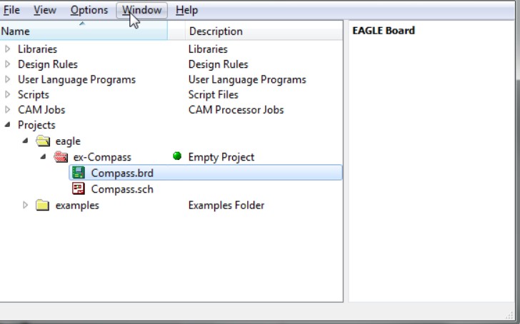
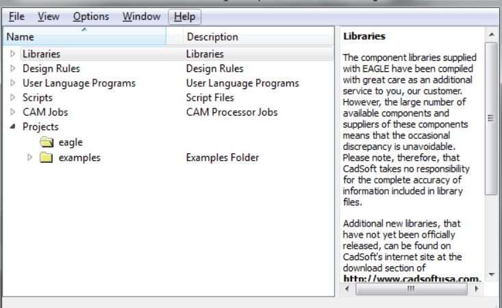
3.Schematic - This is where you draw the schematic for your project. It defines the parts you have in your project, and which pins on the parts should be connected.
4.Board - This is where you lay out the pieces of your project and physically connect the correct pins as defined in the Schematic.
Note: Image borrowed from google.
Step taken to redraw hello board.
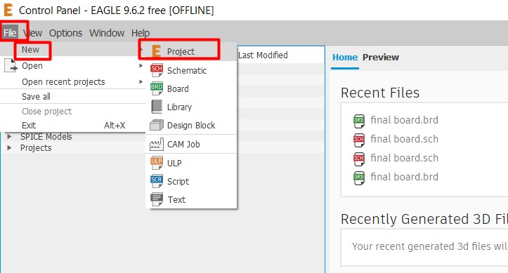
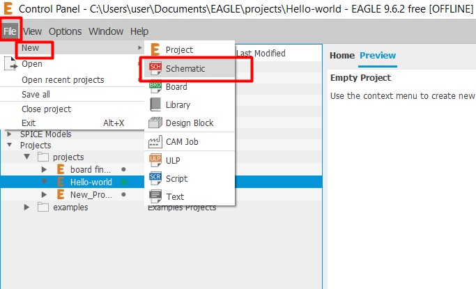
After setting up Eagle, I went to Files ->>> New - >>>Project and then named my project.
After that I need to create a new schemetic diagram, for that go to Files ->>> New ->>>Schemetic.
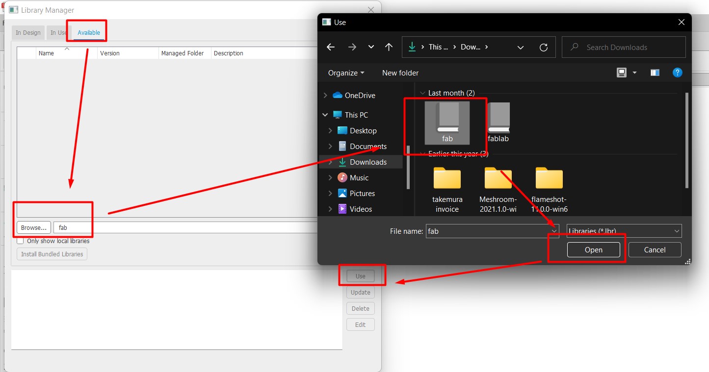
Now, I have to add the Fab library since we are required to use the components from Fab lib.
- To add fab lib.
- Go to library
- open library manager
- click on browse
- select the fab library and click on use.
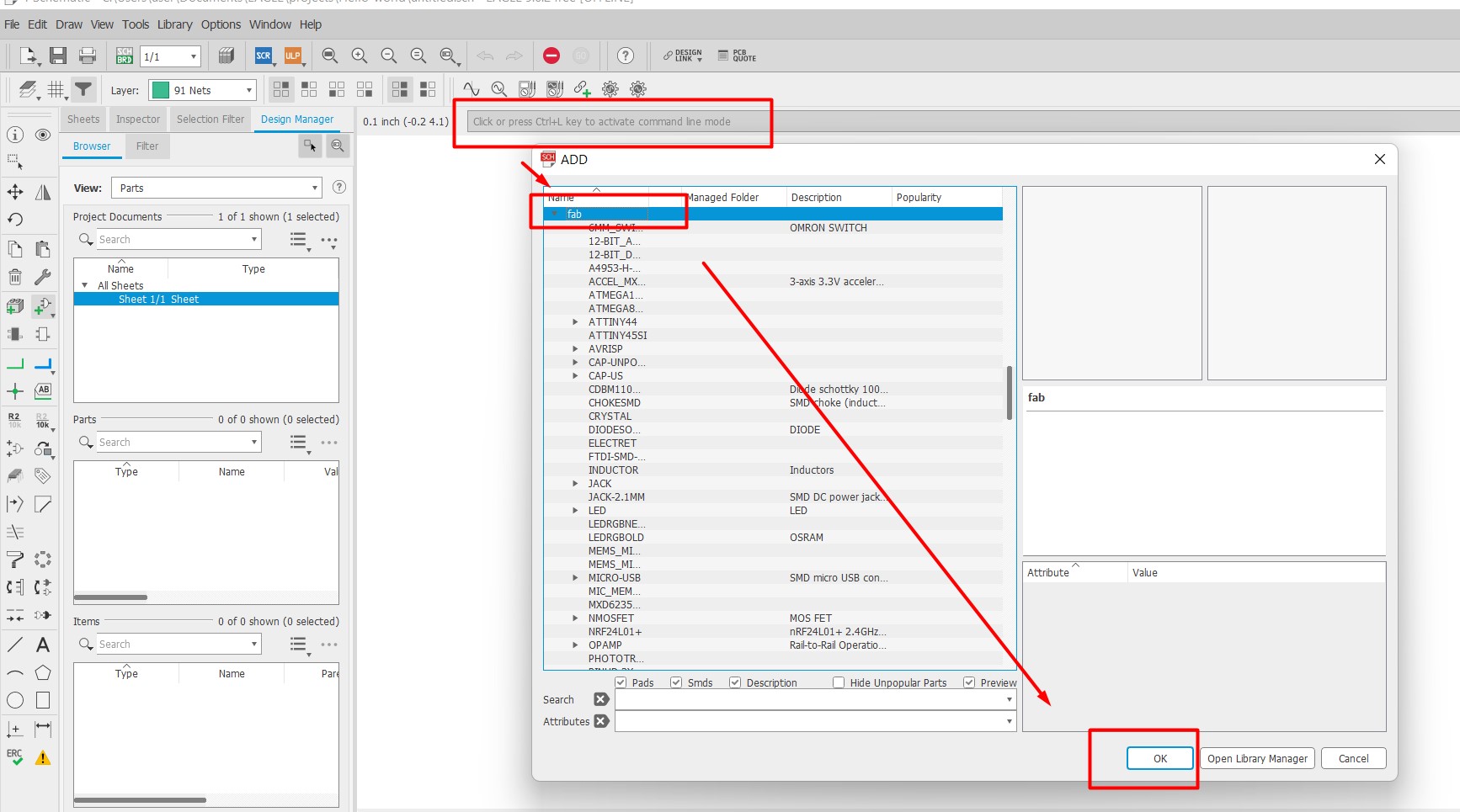
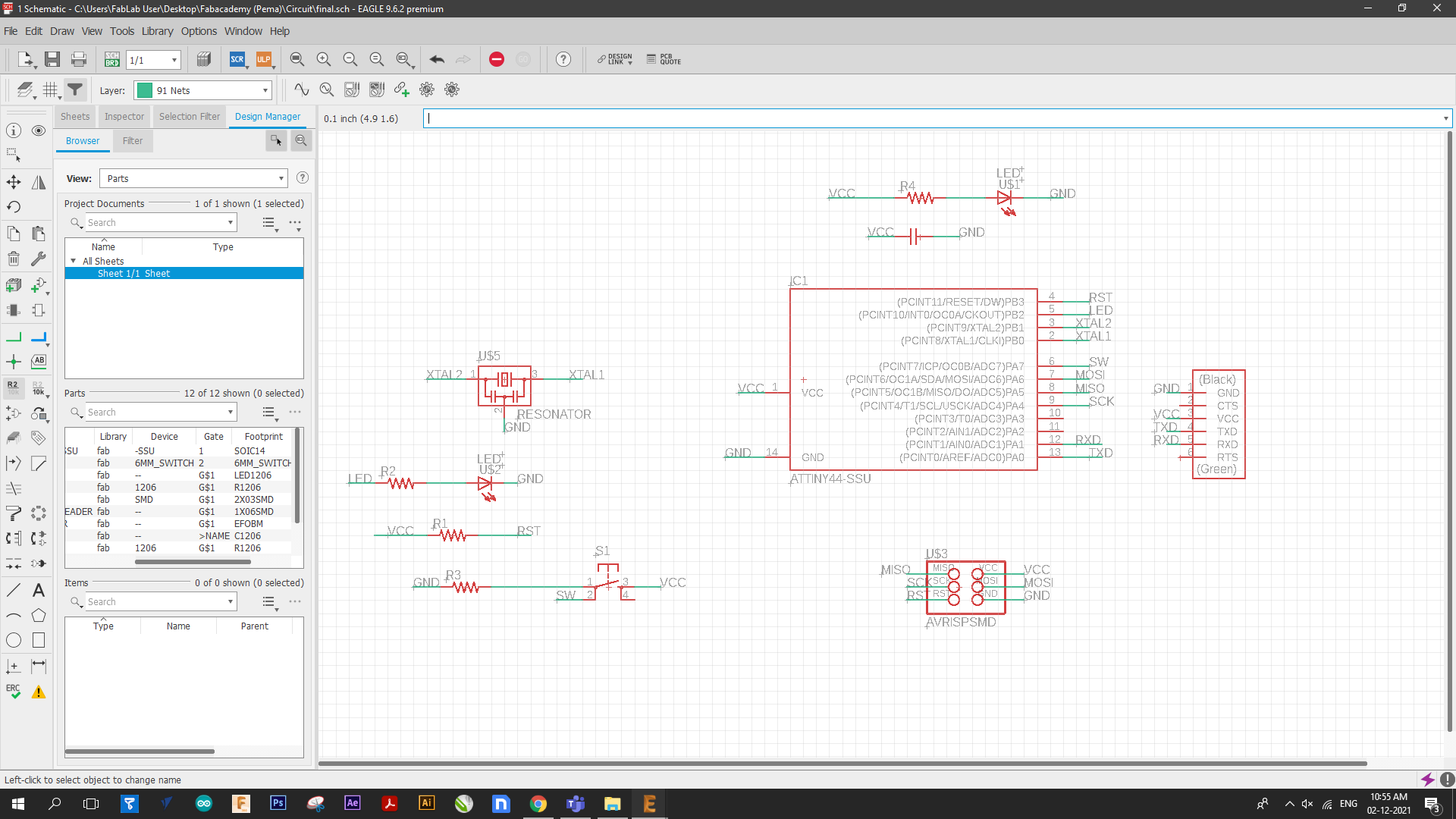
Once I was done with adding the fab library, I start drawing the schemetic diagram using the fab components. In order to use the fab components, on the search bar, type add and then a dialoge box will pop up displaying all the libraries availabe and from there select the fab lib. Once you click on it, the components availabe will show. After this select the components that you require.
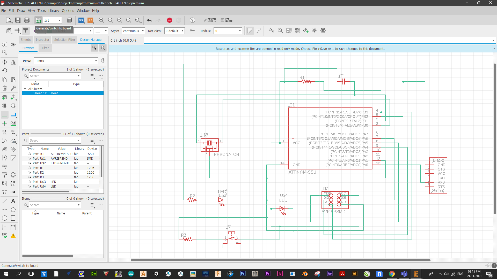
- Components used for the Echo Hello World board
- ATtiny 44
- AVRISPSMD
- FTDI SMD Header
- Resonator
- Switch
- Capacitor
- Resistors (x4)
- LED (x2)
Ater I added all the required components, I had to connect the components using net. So I have learned two ways to connect the components. One is by connecting the components with net like a wire connection and the other is by writing the components name and the same name gets connected.
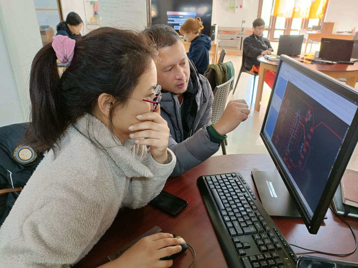
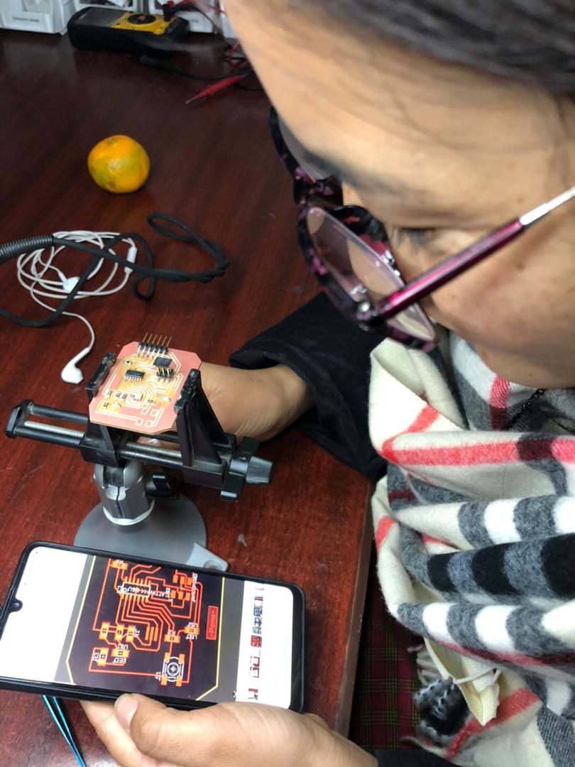
Once the connections were done, I ran the ERC (Electrical Rule Checker) to do the necessary checking. After that, the most craziest part of the whole designing has come. It literally took me three days to finish routing. To route the board, you need to click on the generate/switch to board option.I was advised by my collegues to place the components smartly to avoid criss cross of connections. Below is a picture of me getting help from my friend.
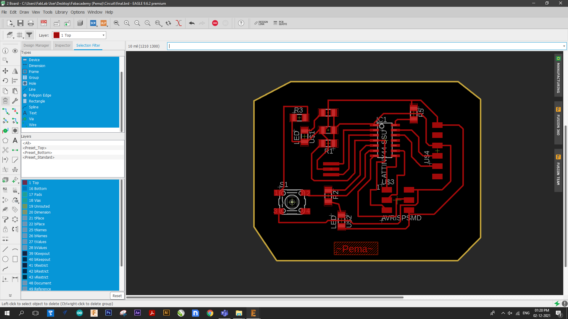
Below is a picture of how the board looks once its done. Phewww!!!!
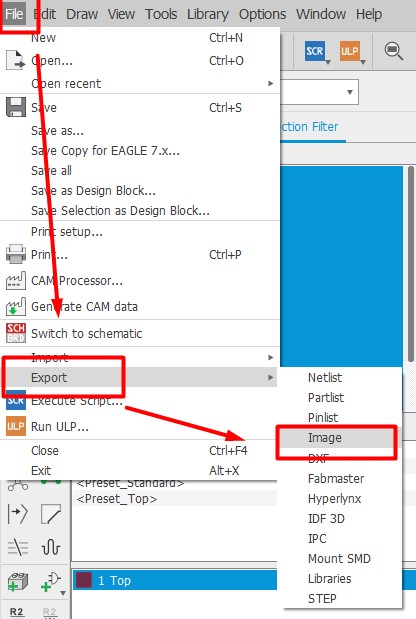
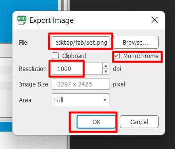
The next step is to generate the .RML file for the SRM-20 so I export the board in the form of .PMG file.
- To generate the .PNG File
- go to layers
- Click on layer setting
- Hide everything except for the top layer and press ok
- After this I exported the board. To do that
- Go to files
- Export
- Image and press ok
- When the export dialouge box pops up
- Browse the file you want your file to be saved
- Select monochrome
- set the resolution to 1000 and then press ok.
- To export the border File
- Click on the layer setting
- Hide all except for dimensions and click ok.
- After that do as for the above.
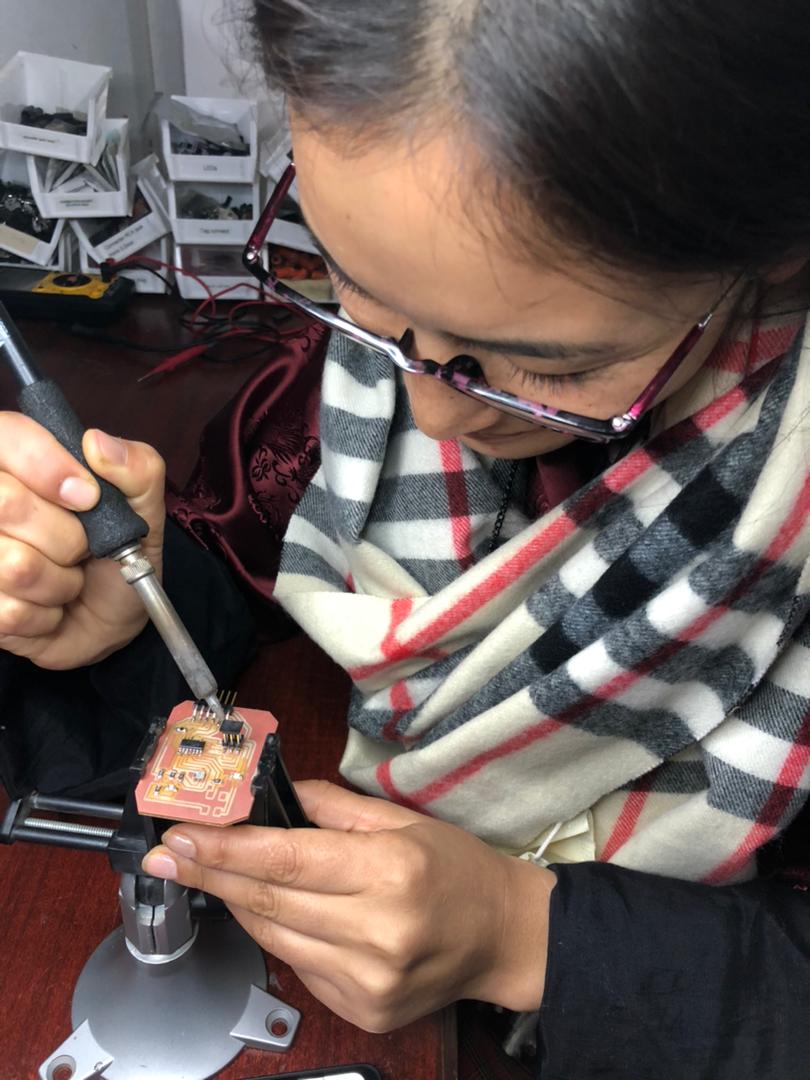
Milling the board
After creating .RML file in the MIT MODS, I milled my PCB board using SRM-20. After that I souldered the components.
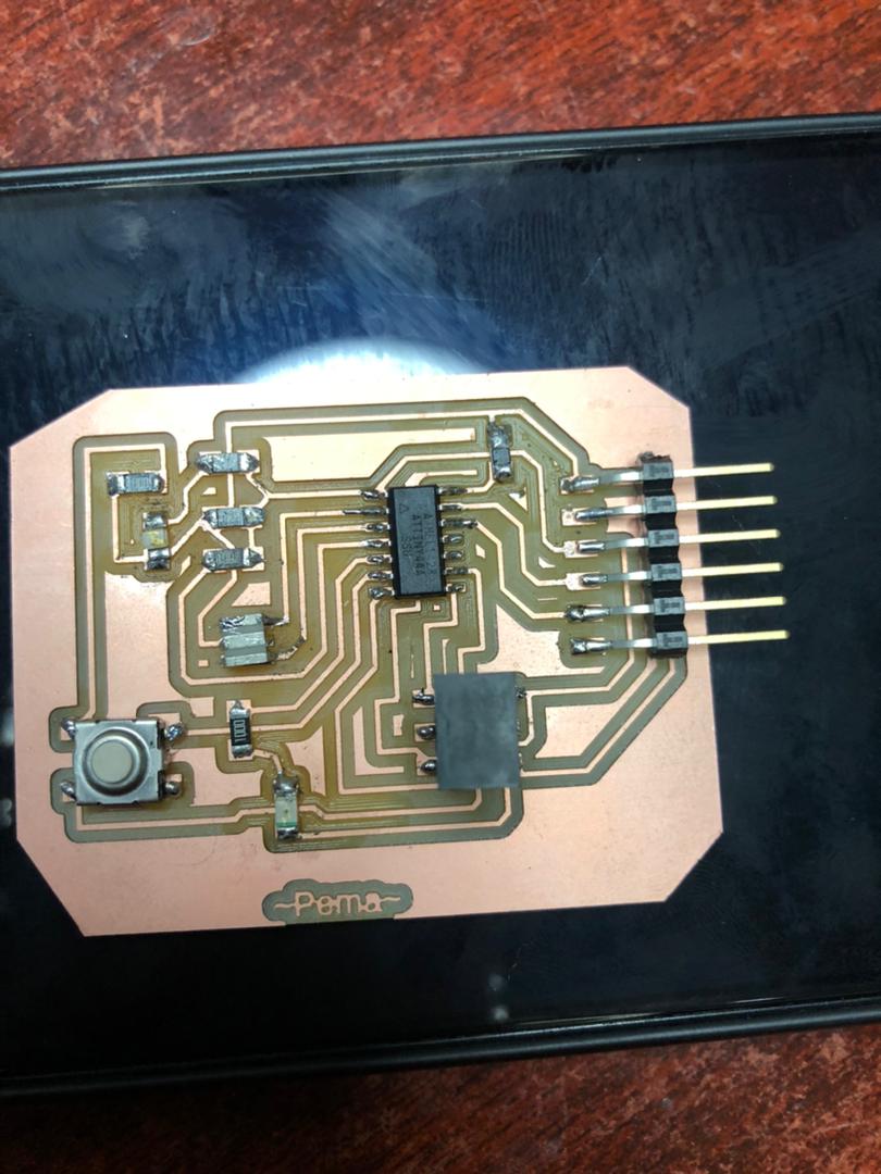
This is how the board looks like after I finished.
Programming my Echo Hello World board.
- In order to program my board,I followed the steps Below
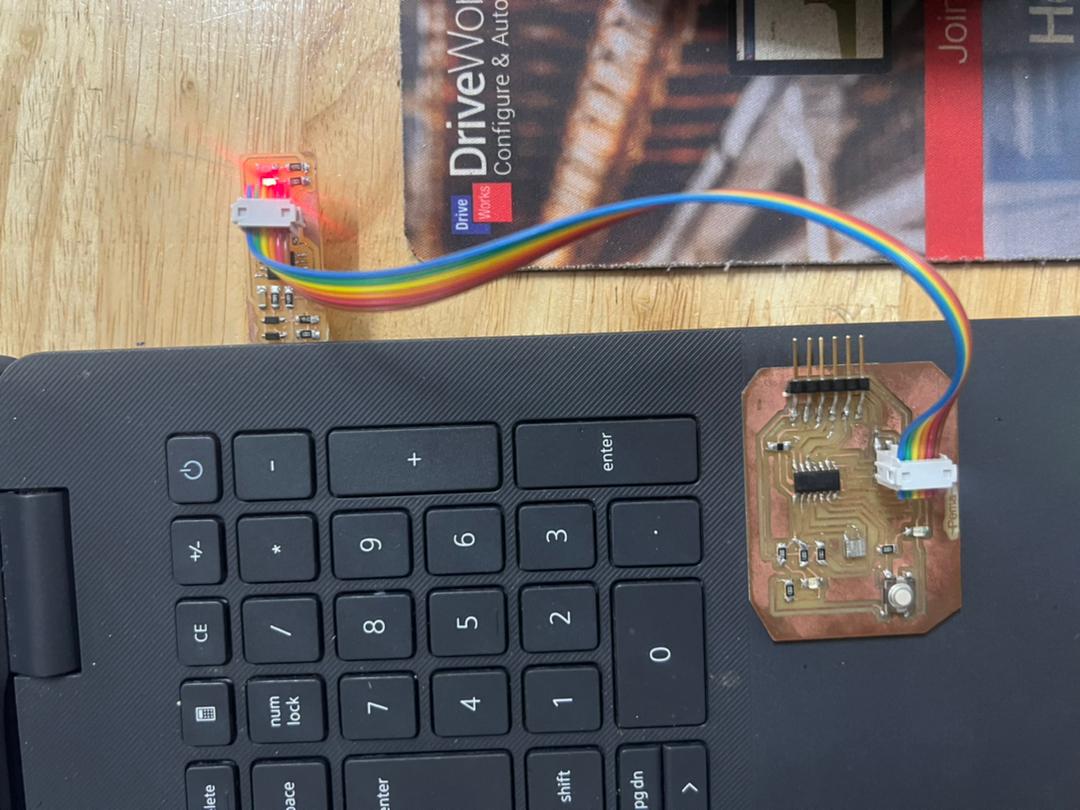
- I used Fab USBtiny to program my board. In order to program the ATtiny board, I need to download the ATtiny library. Since mine was already downloaded, I didnt have to add.
- For Pin connections I refered the ATtiny Pin out chart and did the connections.
- Connecting the pins for programming.
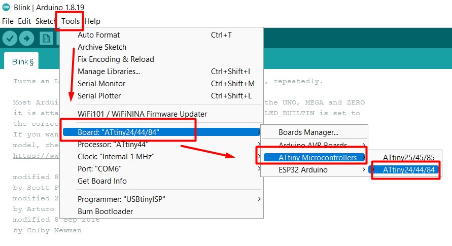
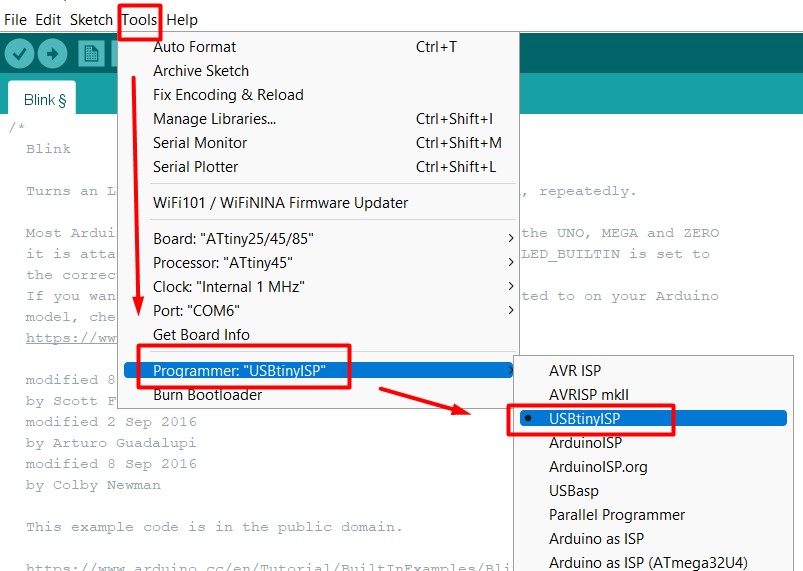
- After that go to Tools ->> Board ->> ATtiny Microcontrollers ->> ATtiny 24/44/84
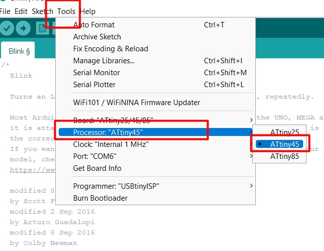
- Go to Tools ->> Processor ->> ATtiny 44
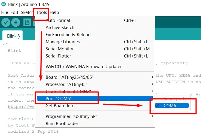
- Tools ->> Port ->> COM 6
- Tools ->> Programmer ->> USBtinyISP
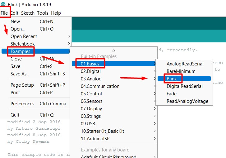
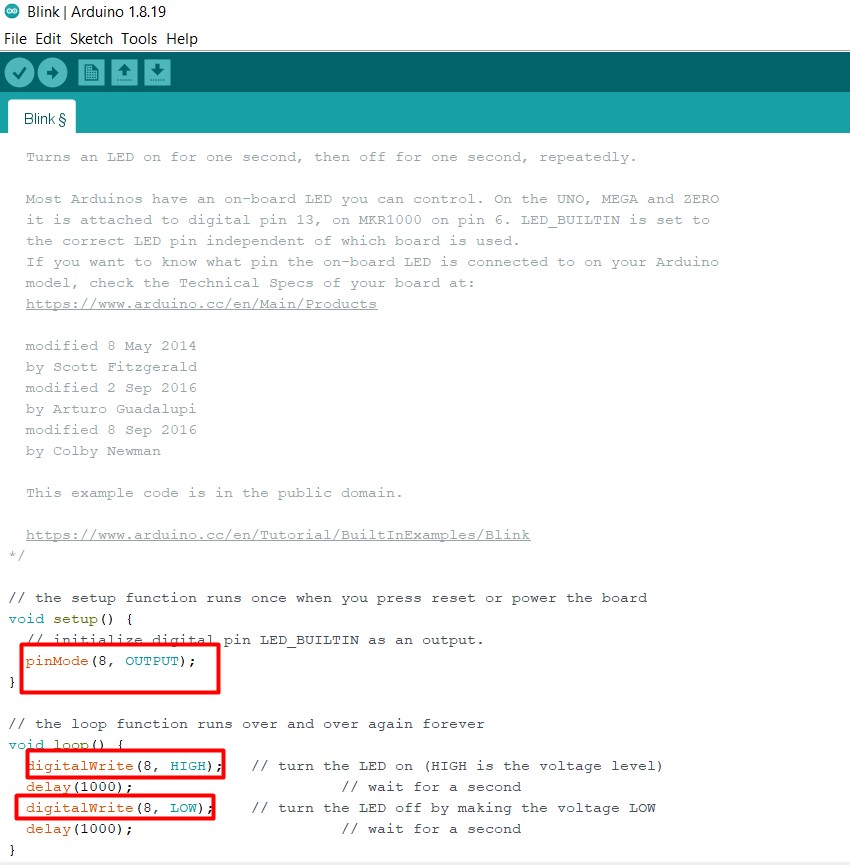
- After this I went to File ->> Examples ->> Basics ->> Blink. to load the basic blinking code.
- And then changed the bulletin pin to 8 as the output pin.I reffered the ATtiny 44 pin out chart.
- And then upload. The program successfuly loaded.

Below is a video of the board after programming.
Group Assignment
Here is the link to our group assignment.All the files are Here
Here is the video link
======= >>>>>>> d5312eec27bae457dd50bcc3d9cdcee965365c51