Group Assignment
A link for our group assignment
Individual Assignment
Designing software
Eagle( Easily Applicable Graphical Layout Editor)
EAGLE is a scriptable electronic design automation application with schematic capture, printed circuit board layout, auto-router and computer-aided manufacturing features. EAGLE stands for Easily Applicable Graphical Layout Editor and is developed by CadSoft Computer GmbH. Wikipedia
Developer(s): Autodesk (previously CadSoft Computer)
Initial release: 1988;
Available in: English, German, Hungarian, Chinese, Russian
Operating system: Windows, Linux, Mac OS X, previously also OS/2 and DOS
Stable release: 9.6.2 / 27 May 2020
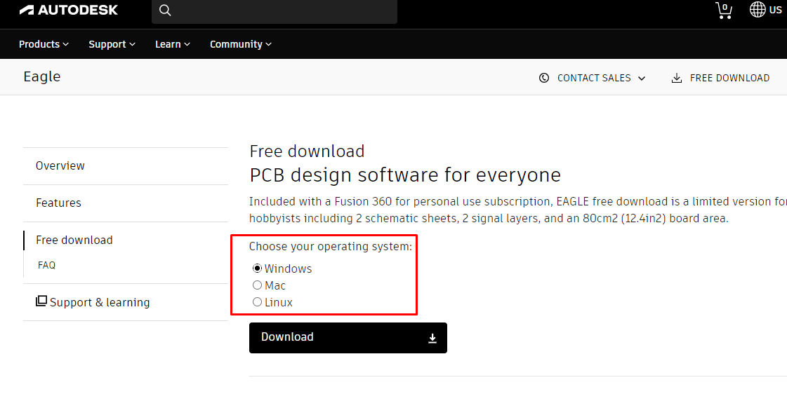
I downloaded the software from here
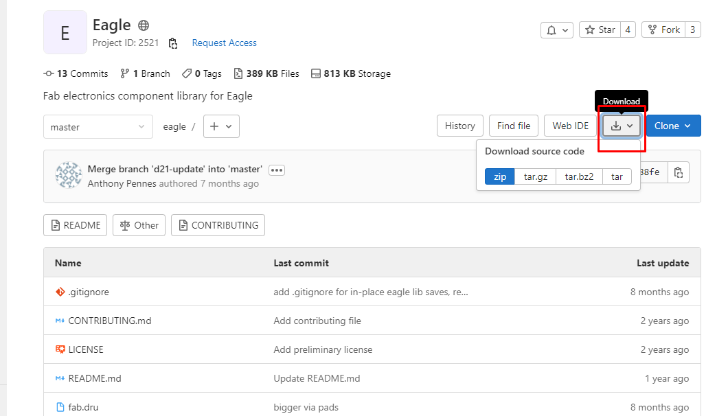
From fab academy website i downloaded Electronic components libraries and added in eagle
When we click on libraries, we will be directed to github page. From there we can clone the httpp or download zip folder to add lab.lbr in eagle library
Designing on eagle
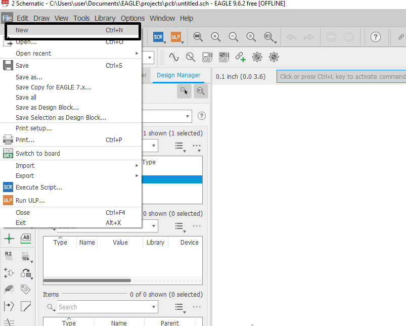
Open the eagle software. click on file and go to new page(ctrl+n)
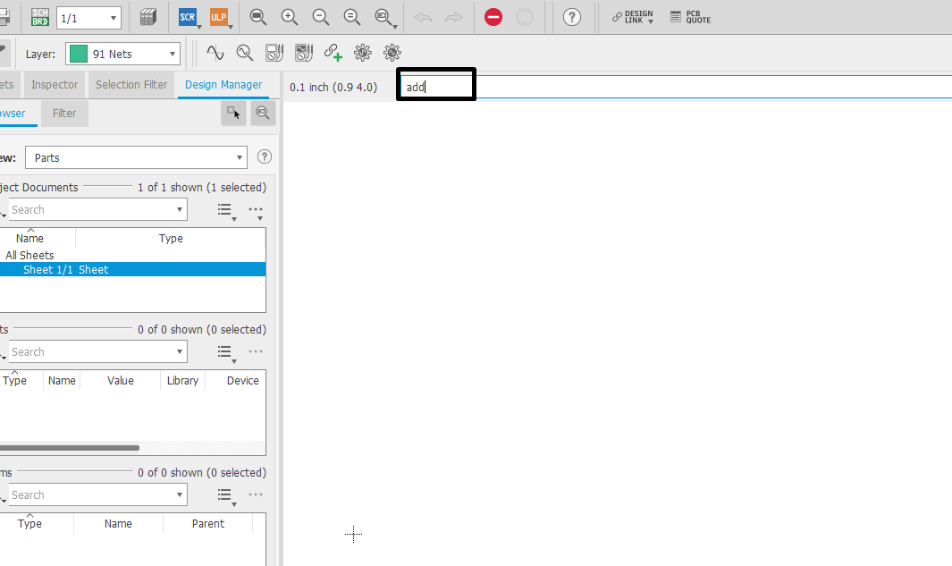
Add fab library to add components to design. so to add libraru type add and enter. than click on open library manager.
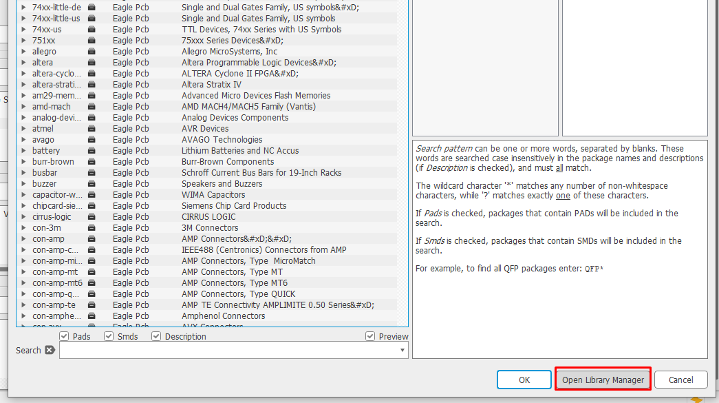
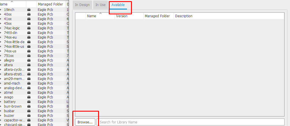
Click on available and browse for the library that is downloaded. after adding the library click on use
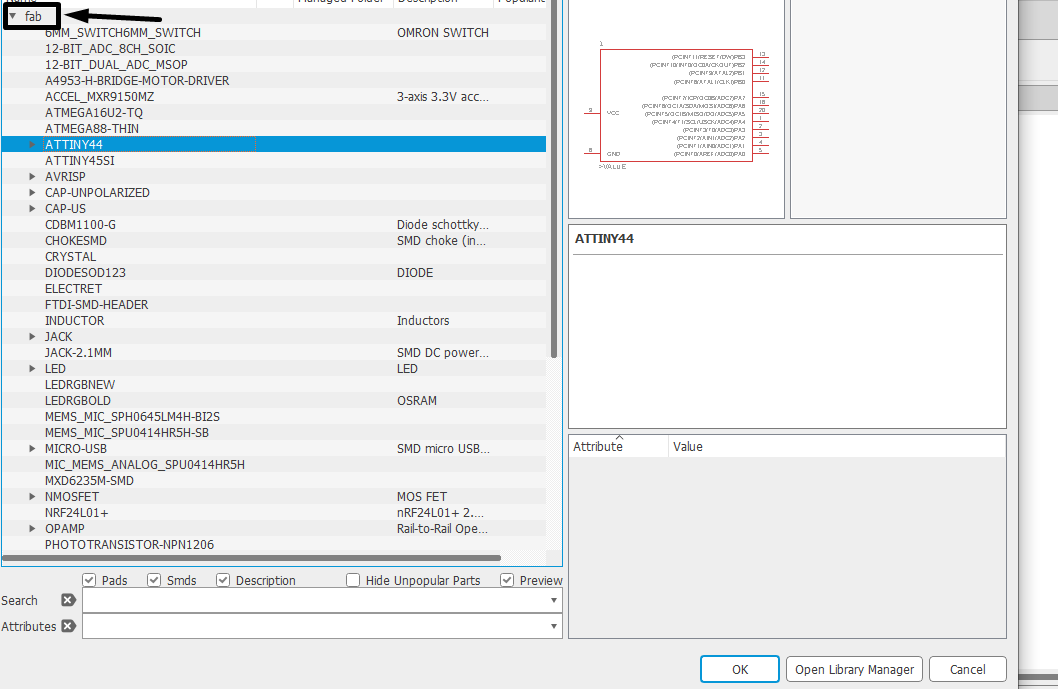
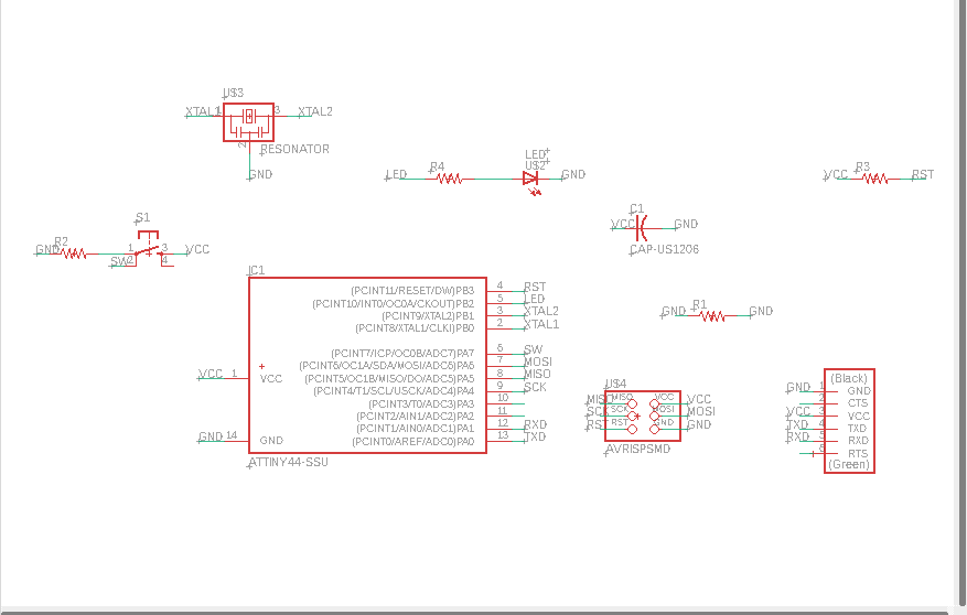
Add the components required for designing from fab library
Tools for netting and labelling(defining connection) on components
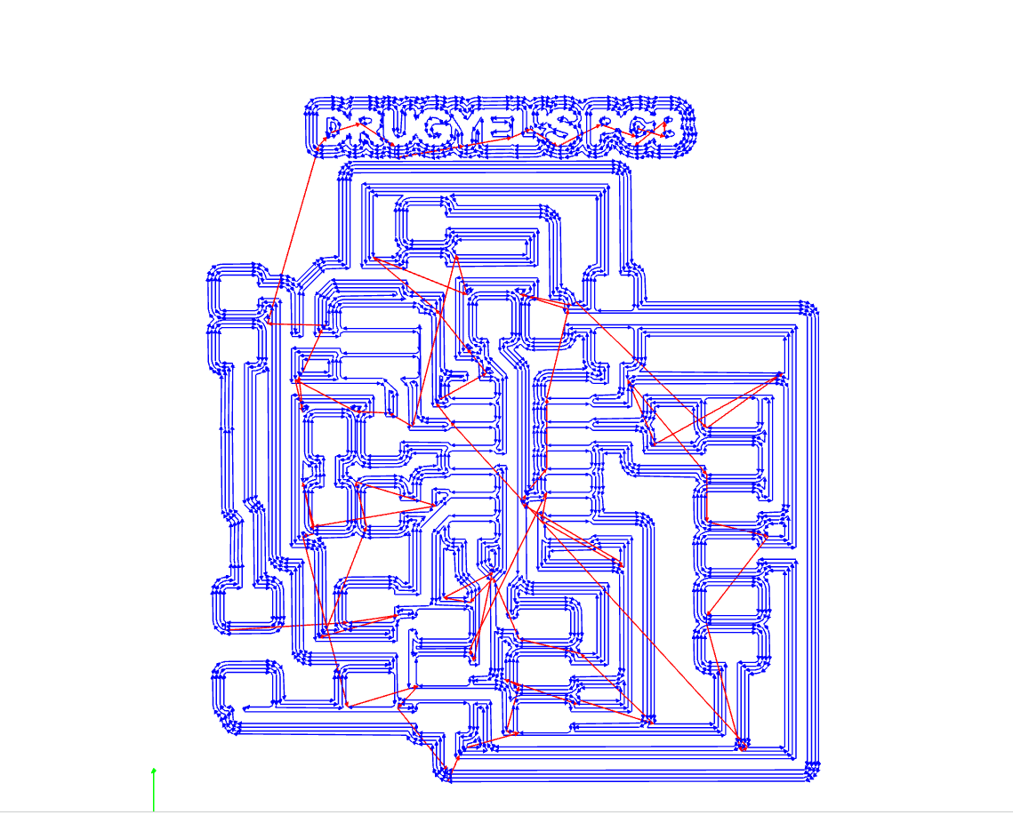
once all components required is added click on BRD for using board to arrange and routing the trace for the components
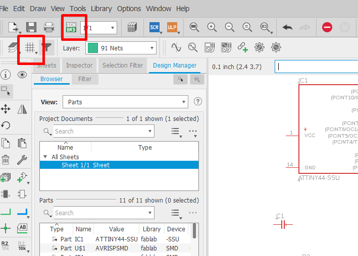
Routing on the board

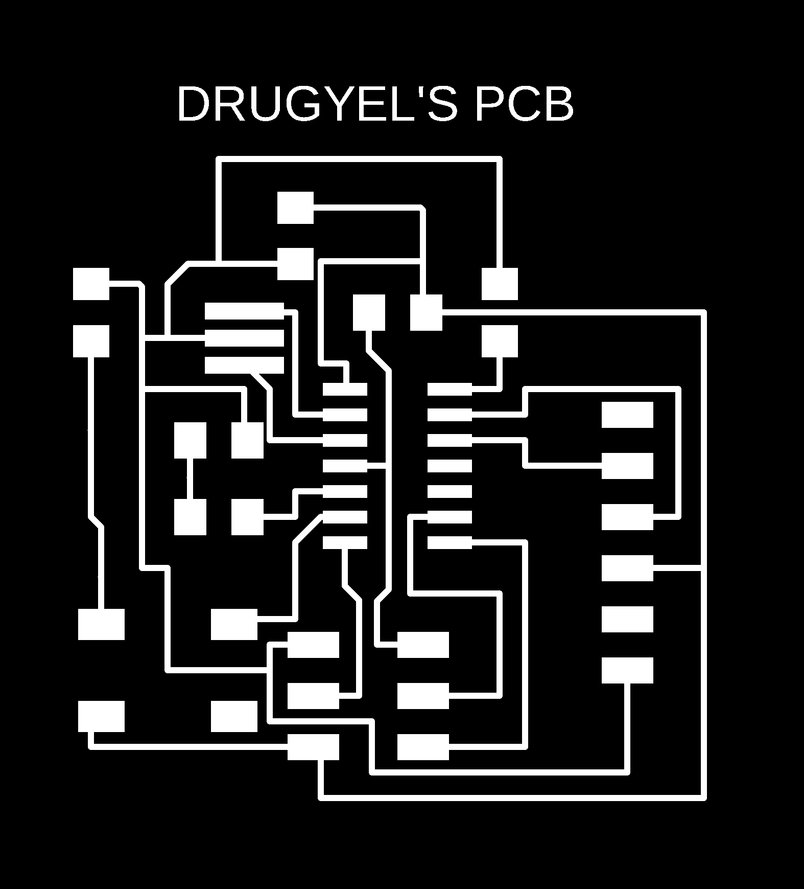
Once we are done with routing we have to export the trace and border to create RML file. I have shown the steps with images below
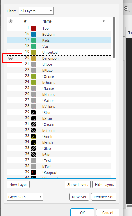
To export the design we need to click on layer
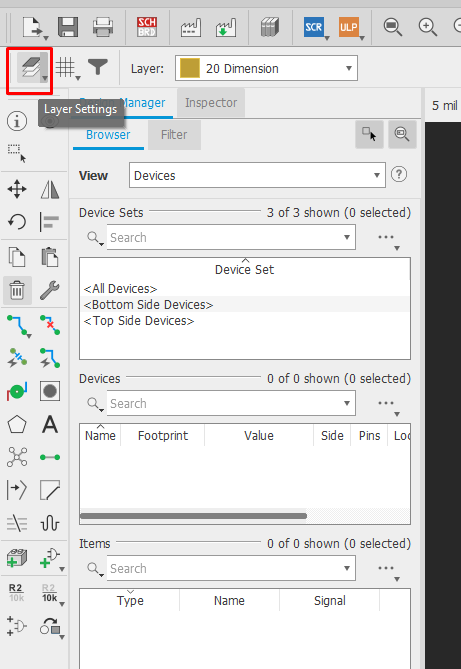
Than click on hide layer and click on top and ok. This is for exporting trace file
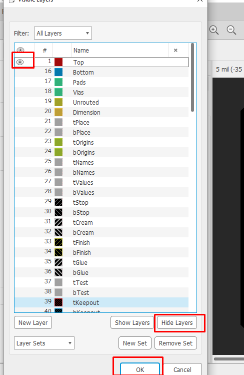
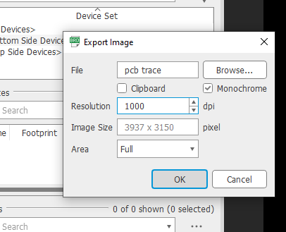
Than click on file and select export and select image
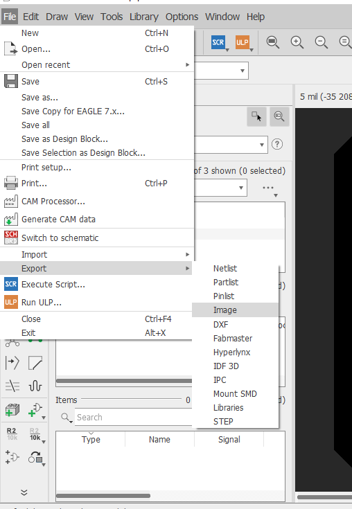
Than click on monochrome and make resolution to 1000.
to export border/ outline file we have to select dimension on layer. Than next steps is same as exporting trace file
Echo-hello board trace and border file in PNG
Milling the board
After exporting the png file i have created RML file using MIT MODS.
Here is a link for mit mods
Steps to create RML file
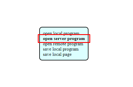
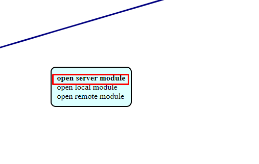
>After MIT MODS is opened right click and select program and click on sever program
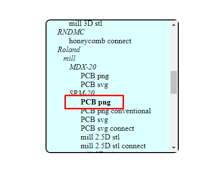
Than select the milling machine. I have used SRM20 to mill so i select SRM20
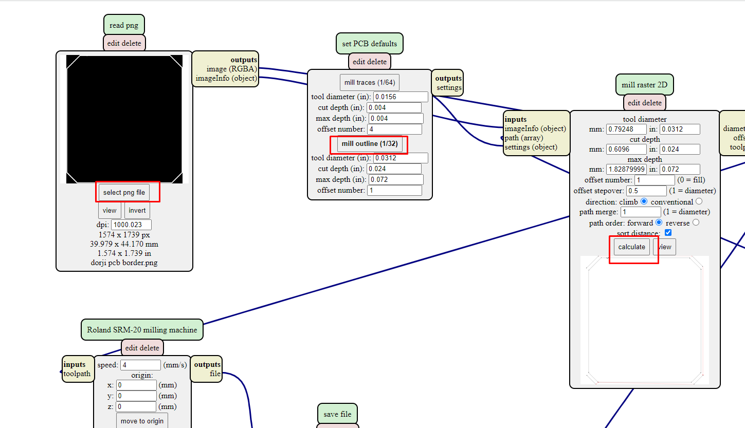
Than select the png file for trace, select mill trace(1/64) and make zero for all 3 axix as shown in picture below. Than click on calculate.
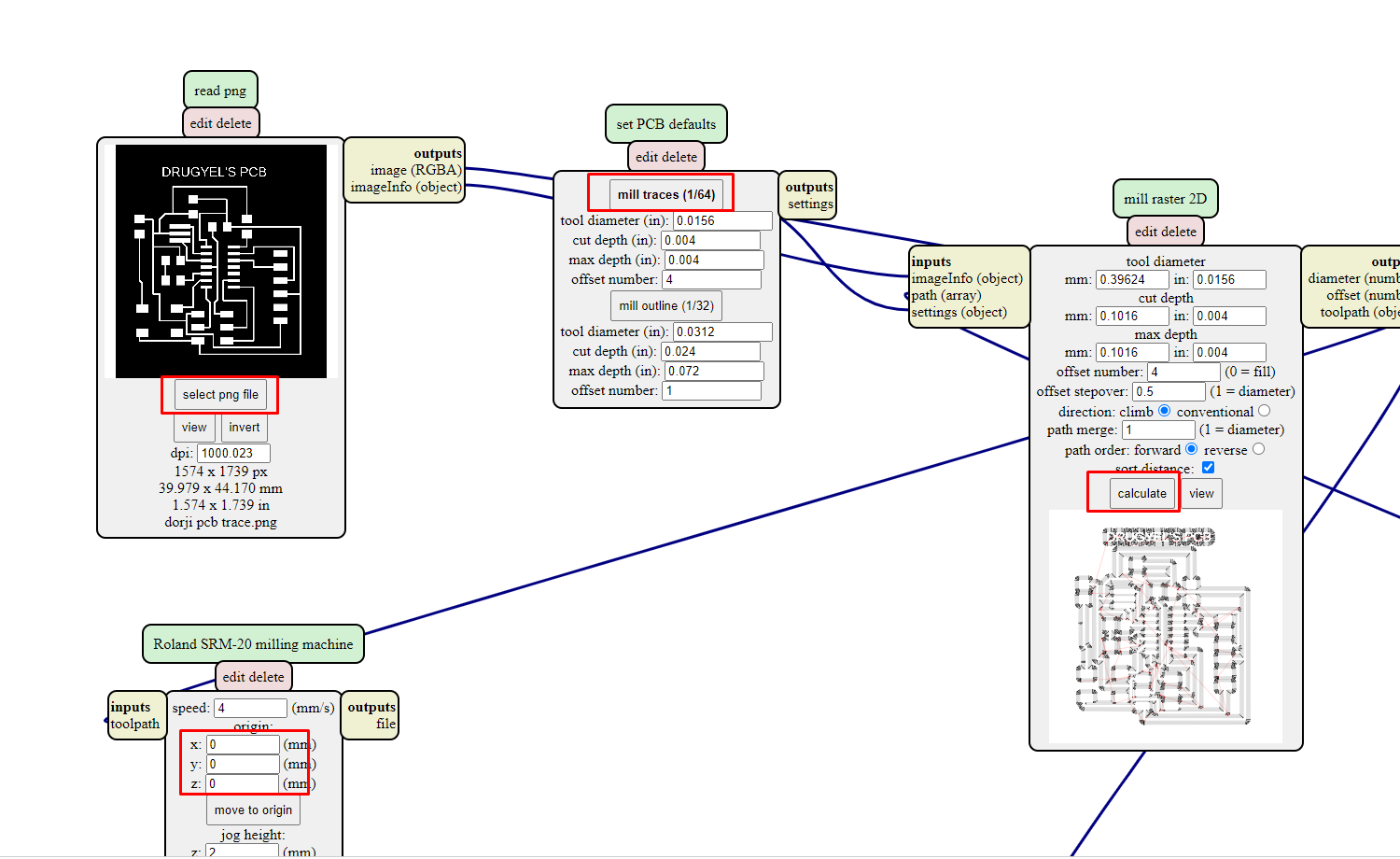
Than a toolpath will be generated as shown in image below
Again right click and select on module and select server module
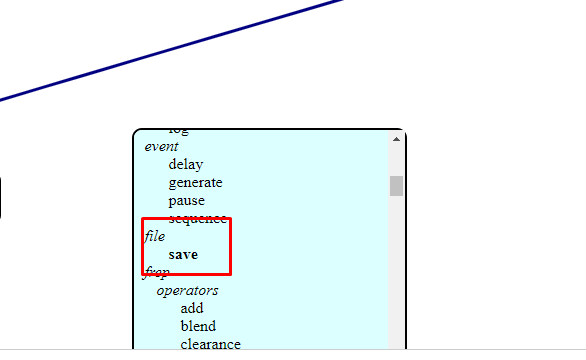
Than go to file and select save
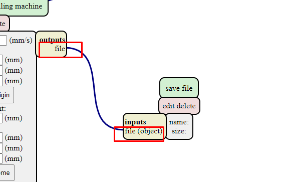
Than connect input file with output file
select the png file of border and select on mill outline(1/32) and click on calculate. The RML file for border will be created.
V-Panel for SRM20
V-panel is a software for controlling SRM20 machine.
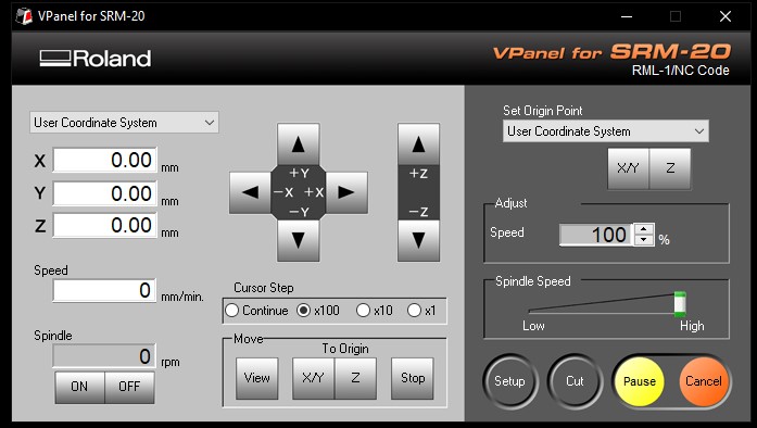
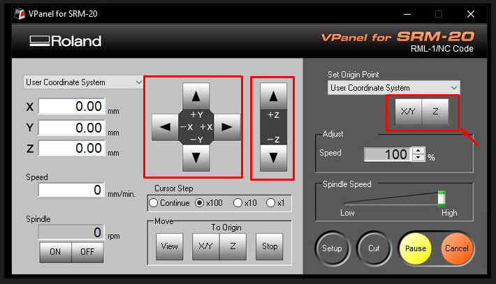
On V-panel software we have to do set x, y and z axis to create an origin. once all 3 axis is set we have to save it by clinking on XY and Z as shown in picture below. after setting origin point click on cut to import the RML file and to mill.
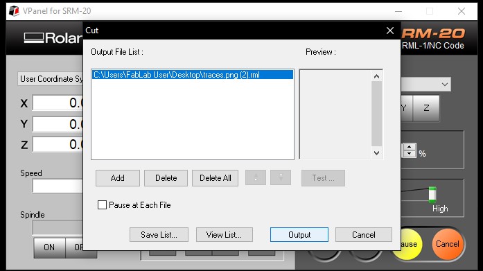
Than delete the existing file and click on add to add the RML file. Than click on output to start the milling.
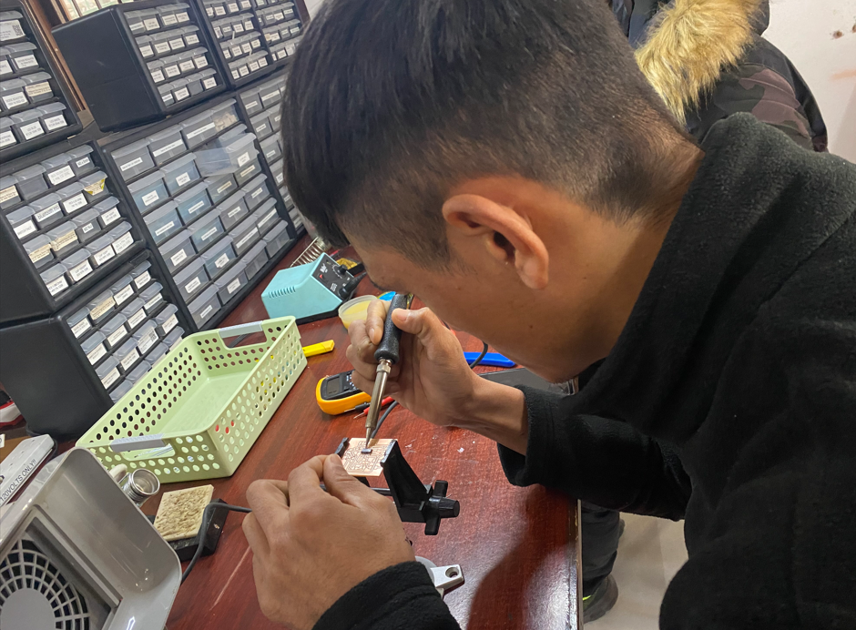
Soldering Hello board
After milling the hello board i did soldering on my board.
List of components i have used for my hello board
PCB is also known as Printed Wiring Board. PCB is an electronic circuit used in a device to provide a path to its electronic components. PCB contains copper plate on one side where we have to trace route for current to flow. To design the path on the board first we need to do routing in Eagle software and we have to do milling
Components for Echo-hello board
1. Resistor
It is an electronic component who has two teminal that implements circuit resistance. Resistor are used to reduce current flow or divide voltage. The unit of resistor is measured in ohms.
For instance. Led requires 1.2V to 3.6V. If the current supply is 5V than Led will blick. so in that case if resistor is installed before led, only voltage required for led will be supplied.
2. Capacitor
A capacitor is device that stores electrical energy and it has two terminal. It is a component that draws energy from a battery and stores it.
For instance. If inflow of current is 5V but the required current for led is only 1.5V. The capacitor will store the excess voltage but 1.5V will pass contineously. Even when the power supply is off capacitor will pass energy that has been stored.
3. Diode
Diode is a semiconductor device with two terminal but it allows flow of current in only one direction. Diode can be used to turn alternative current into direct current.
For instance. The solar panel receives the energy from send and send it to battery but the energy from battery will also flow current to solar panel. So if we use diode the energy will flow only towards battery. It wont allow energy to flow from battery to solar panel.
4. Resonator
A resonator is a device that exhibit resonant behavior associated with a very high reactive peak at the resonant frequency. Resonator cancels or reduce certainrange of sound frequencies.
For instance. The sound produce by car engine is very loud so to reduce the sound of car muffler has been used. The use of muffler and resonator is same.
5. Tact Switch
It is an electronic component or device that can switch an electrical circuit. It can divert circuit from one conductor to another. switch is used to interupt the current flow in a circuit. Switches are binary device, they are either on or off. Switch is a input device
6. LED(Light Emiting Diode)
LED is a semiconductor diode that emits light when current flows through it. It is a output device.
7. FTDI-SMD header
FTDI stands for Future Technology Devies International Limited. It is a semiconductor device which is used for connecting the PCB board with arduino board. The connection will be done by jumper wire but we have to follow arduino data sheet. We have to define input and output pin. The programming to micro-controller from arduino is done through FTDI.
Attiny44
Attiny44 is a micro controller or programmer. Attiny44 act as the brain because all the commands are given by it.Attiny was first released in 1999 by Atmel but acquired by Microchip Technology in 2016. All the program has to be done in Attiny44 from arduino.
Programming Echo-hello board
To program usbtiny i need to download adafruit drivers and install it
Here is a link to download the drivers
after downloading the drivers i set up board and port for programming
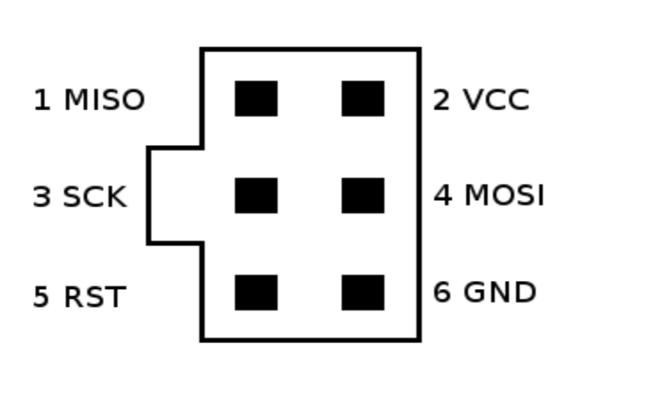
Than i connect FabISP to echo hello board using Jumper wire. I followed pinout diagram of ATtiny44(Hello board) and ATtiny45(ISP) to make the connection for programming.
We can even make the connection using SPI cable. The pinout diagram is shown below for SPI.
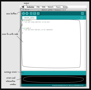
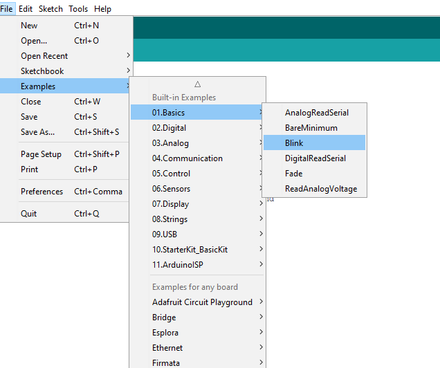
Here is a layout of arduino_IDE and its funchtion
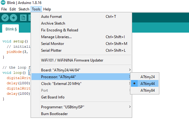
First i set my board to attiny24/44/84, than set proccessor as ATtiny44 and than programmer as USBtinyISP.
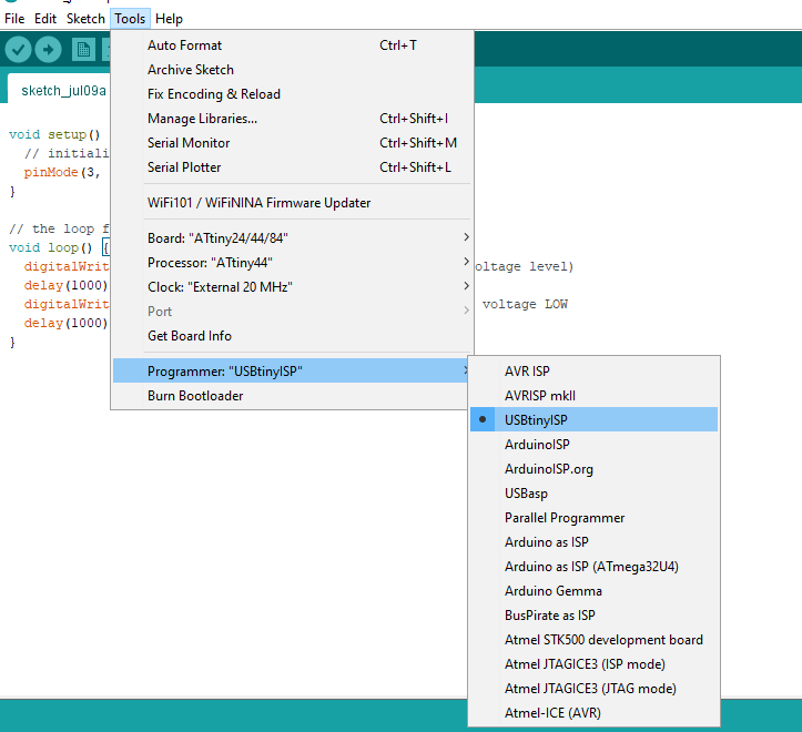
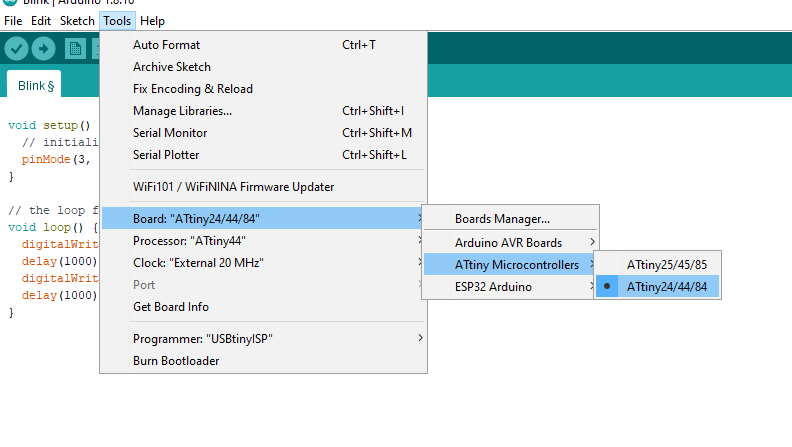
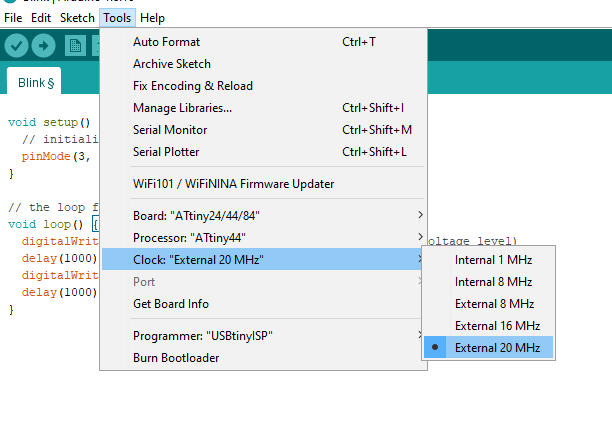
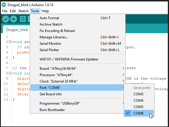
Than I click on tools, port and select COM6 and again on tools, clock and external 20MHz.
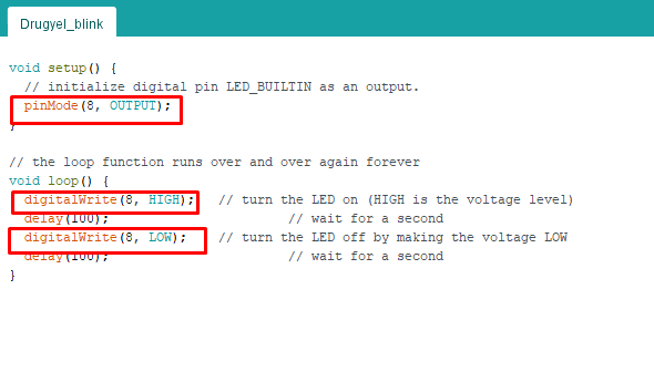
After that I open examples and used blink code. I changed my output to pin 3 and upload. It was successfully uploaded.
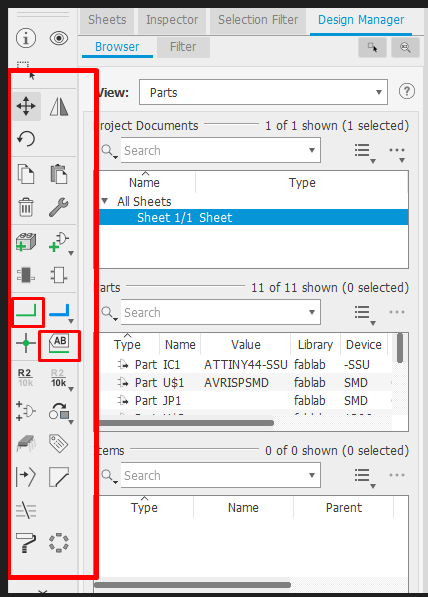
Board design file and schematic file
Board file
PCB Board fileSchematic file
PCB schematic fileSuccessful working of the led blink code
Board design file and schematic file
Board file
PCB Board fileSchematic file
PCB schematic file